1
Caution: This document contains mixed page sizes (8.5 x 11 or 11 x
17), which may affect printing. Please adjust your printer settings
according to the size of each page you wish to print.
Service
Manual
2 5 t o I 8 0 kW
Generators
And Controls
Troubleshooting and
Test Procedures For
Generators
Regulator
Controls
900-0150
10-78
Printed in U.SA
Redistribution or publication of this document,
by any means, is strictly prohibited.
Safety Precautions
The following symbols in this manual highlight conditions potentially dangerous to service personnel, or
equipment. Read this manual carefully. Know when
these conditions can exist. Then take necessary
steps to protect personnel as well as equipment.
This symbol is used throughout the
I W A R N I N G 1 manual
to warn of possible serious
personal injury.
This symbol refers t o possible
equipment damage.
PROTECT AGAINST MOVING PARTS
Avoid moving parts of the unit. Avoid use of loose
jackets, shirts or sleeves due to danger of becoming
caught in moving parts.
Make sure all nuts and bolts are secure. Keep power
shields and guards in position.
If you must make adjustments while the unit is
running, use extreme caution around hot manifolds,
moving parts, etc.
Do not work on this equipment when mentally or
physically fatigued.
GUARD AGAINST ELECTRIC SHOCK
Disconnect electric power before removing protective shields or touching electrical equipment. Use
rubber insulative mats placed on dry wood platforms
over floors that are metal or concrete when around
electrical equipment. Do not wear damp clothing
(particularly wet shoes) or allow skin surfaces to be
damp when handling electrical equipment.
Disconnect batteries to prevent accidental engine
start. Jewelry is a good conductor of electricity and
should be removed before working on electrical
equipment.
Use extreme caution when working on electrical
components. High voltages cause injury or death.
Follow all state and local codes. To avoid possible
personal injury or equipment damage, a qualified
electrician or an authorized service representative
must perform installation and all service.
EXHAUST GAS IS DEADLY!
Exhaust gases contain carbon monoxide, a poisonous gas that might cause
unconsciousnessand death. It is an odorless and colorless gas formed during
combustion of hydrocarbon fuels. Symptoms of carbon monoxide poisoning
are:
Dizziness
Headache
Weakness and Sleepiness
Vomiting
Muscular Twitching
Throbbing in Temples
If you experience any of these symptoms, get out into fresh air immediately,
shut down the unit and do not use until it has been inspected..
Thebest protection agalnst carbon monoxide inhalation Is proper installallon
and regular, frequent visual and audible inspections of the complete exhaust
system. If you notice a change in the sound or appearanceof exhaust system,
shut the unit down immediately and have it inspected and repaired at once by a
competent mechanlc.
Redistribution or publication of this document,
by any means, is strictly prohibited.
Y
.
GENERATORS AND CONTROLS
25 kW 180 kW
.
-
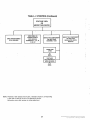
TABLE OF CONTENTS
'
PAGE
' Introduction ..........................................
:................ 2
Generator - Section I .................................................
5
Question and Answer Troubleshooting Guides. ..........................
8
Adjustments and Procedures ............................................
16
Generator - Section II ...............................................
26
Question and Answer Troubleshooting Guides. .........................
27
35
Adjustments and Procedures ...........................................
Index of Generator Adjustments and Procedures. .......................
38
Control Section 111 .................................................
39
Question and Answer Troubleshooting Guides. .........................
40
Adjustments and Procedures ..........................................
51
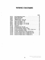
Wiring Diagrams .....................................................
53
.
-
ONAN RECOMMENDS THAT ALL SERVICE, INCLUDING
INSTALLATION OF REPLACEMENT PARTS, BE PERFORMED
BY QUALIFIED PERSONNEL.
.
I
I
I
Redistribution or publication of this document,
by any means, is strictly prohibited.
INTRODUCTION
FOREWORD
'
,
tion on later UR generator. Section 11 contains
troubleshooting information for the later model
UR generator where the exciter diode rectifier
assembly has been relocated into the contrd
panel. Refer to Table 1 for a description of t / : f .
appropriate section for your generator.
This manual provicds troubleshooting and repair
information for ONAN series UR generators. It is
intended to provide the maintenance technician,
serviceman or Onan distributor with a logical
procedure to enable him to systematically locate and
'repair malfunctions in the generator and control
systems. This information is not applicable to the
prime mover; refer to the engine manufacturer's
manual.
2 . CONTROLS - S e c t i o n 111 c o n t a i ! $ s
troubleshooting guides and procedures lor
testing and repairing the system controls, P
description of the components and an analysiz' ti+
the module circuitry is included.
Repair information is not extensive because the plugin solid-state printed circuit modules lend themselves
more to replacement than repair. ONAN does not
recommend repair of the printed circuit module,
except at the factory and has initiated a returdexchange service, obtainable through distributors,
whereby faulty modules can be returned and exchanged for good units. For more information, contact your distributororthe ONAN service department.
TEST EQUIPMENT
Most of the tests outlined in this manual can be
performed with an AC-DC multimeter such as a
Simpson 260 VOM.
Application of meters or high heat soldering
Other suggested test instruments are -
irons to modules by other than qualified
personnel can result in unnecessary and expensive damage.
ONAN multitester Part No. 420-0303
Wheatstone or Kelvin bridge
This rnanual is arranged as follows:
- Section I contains general
specifications
on the U R generator,
troubleshooting guides and procedures for
testing and repairing of the early UR generator
with VR22 exciter regulator and general informa-
i . GENERATOR
Exercise care when purchasing a foreign
made VOM. Some units deliver +9VDC,
others, +22VDC to the circuit under test on R x 1 scale. Maximum
recommended voltage is +l.SVDC. Damage to solid state devices
can result from excessive voltage application.
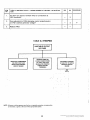
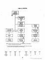
I
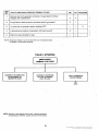
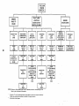
GENERATING SET
MALFUNCTION
I
GENERATOR FAILS
SEE GENERATOR
SECTION I OR II
ENGINE FAILS
SEE ENGINE
SERVICE MANUAL
CONTROL FAILS
CONTROL SECTION Ill
2
Redistribution or publication of this document,
by any means, is strictly prohibited.
I
'
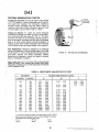
TABLE 1. GENERATOR SPECIFICATION BREAKDOWN
Section 1
Spec A
kW Model
25.0 EK
30.0 EK
Penn EK
25.0 DDA
30.0 DDB
30.0 DEH
25.0 MDEH
30.0 MDEH
Penn DEH
37.5 EM
45.0 EM
Penn EM
37.5 DEF
45.0 DEF
Penn DEF
37.5 DYJ
45.0 DYJ
40.0 DDB
50.0 DDB
40.0 DEG
50.0 DEG
Penn DEG
40.0 MDEG
50.0 MDEG
45.0 KB
55.0 KB
Penn KB
50.0 DYA
60.0 DYA
Penn DYA
55.0 EN
70.0 EN
Frequency
50 Hz
60 Hz
50 Hz
60 Hz
60 Hz
50 Hz
60 Hz
50 Hz
60 Hz
50 Hz
60 Hz
50 Hz
60 Hz
50 Hz
60 Hz
50 Hz
60 Hz
50
60
50
60
Hz
Hz
Hz
Hz
50 Hz
60 Hz
60 Hz
60 Hz
E
D
E
-
D
D
C
E
E
D
E
H
F
G
-
G
E
F
F
E
R
P
Q
E
C
D
-
Section 2
Begin
Spec
kW Model
55.0 KB
55.0 KB
"enn KB
50.0 DYC
75.0 DYC
30.0 DYC
100.0 DYC
'enn DYC
70.0 KR
35.0 KR
Penn KR
75.0 DYC
30.0 DYC
30.0 DYD
100.0 DYD
Penn DYD
35.0 WA
115.0 WA
100.0 DYD
125.0 DYD
Penn DYD
115.0 WE
140.0 WE
125.0 WE
150.0 WE
125.0 DYG
150.0 DYG
Penn DYG
130.0 DFE
155.0 DFE
Penn DFE
140.0 WB
170.0 WB
145.0 DYG
175.0 DYG
Penn DYG
150.0 DFE
180.0 DFE
Penn DFE
F
F
F
A
A
G
G
G
G
F
F
F
J
J
J
A
A
A
A
H
H
H
H
H
S
S
S
F
F
F
A
A
Frequency
1
Section 1
Spec A
ThN
R
P
50 Hz
60 Hz
Q
50 Hz
60 Hz
50Hz
60 Hz
D
B
-
'
j
50 Hz
60 Hz
c
R
P
Q
50 Hz
60 Hz
50 Hz
60 Hz
50 Hz
60 Hz
50 Hz
60 Hz
50 Hz
60 Hz
50 Hz
60 Hz
50 Hz60'HZ
50 Hz
60 Hz
D
B
C
A
B
H
G
C
A
B
B
B
B
B
C
A
B
-
-
50 Hz
60 Hz
50 Hz
60 Hz
K
J
C
A
B
50 Hz
60 Hz
-
-
'
Section 2
Begin
Spec
S
S
S
E
E
G
G
'E
S
S
S
E
E
. D
D
D
J
J
D
D
D
-
D
D
D
H
H
H
L
L
D
D
D
H
H
H
3
Redistribution or publication of this document,
by any means, is strictly prohibited.
UR G’ENERATOR VOLTAGE/CURRENT OPTIONS
RATING
HE
-
I_
:ode
:ode
1-PHASE
STANDARD
a
2K g
- g
@@
15
515 -
4
1-PHASE
SPE
-
50
60
-
0
L--
0
- - -
c c 0 0
- -g
-g
-
3-PHASE
-
0 0
@
-
kVA
25.0
31.25
30.0
37.50
37.5
46.80
X
213
204
142
135
130
123
123
118
71
40.0
50.0
X
227
217
152
144
139
131
131
126
76
45.0
56.25
X
X
256
245
234
171
162
156
148
148
141
135
135
50.0
62.5
X
X
284
272
260
190
180
173
164
164
157
150
150
55.0
68.75
X
X
313
299
286
209
198
191
180
180
173
165
165
60.0
75.0
180
180
62.5
78.13
65.0
81.25
195
195
70.0
87.5
X
X
398
380
365
266
253
243
230
230
220
210
210
133
75.0
93.75
X
X
426
408
391
285
271
260
246
246
235
226
226
455
435
304
289
262
262
251
80.0
100.0
85.0
106.25
142
X
136
156
X
95
234
355
X
340
X
237
X
443
X
469
112,5
95.0
118.75
X
100.0
125.0
X
X
115.0
143.75
X
X
540
516
568
543
.
82
226
217
78
205
205
279
295
312
150.0
125.0
156.25
X
130.0
162.50
X
140.0
175.0
X
256
256
27 1
271
343
330
312
312
298
521
380
361
347
328
328
314
301
599
437
415
399
377
377
361
346
X
X
E E
43
41
49
68
65
62
72
69
66
85
81
78
95
90
87
104
99
k y
600
45
36
74
68
54
82
75
60
95
90
83
66
104
98
90
72
108
103
113
107
98
78
126
121
115
105
84
142
135
130
123
113
90
152 ’
144
139
131
147
139
128
102
135
108
113
156
148
180
171
165
156
301
190
180
173
164
150.
120
346
218
207
200
189
173
138
376
237
226
217
205
188
150
247
235
226
213
266
253
243
230
210
168
275
262
252
238
285
271
- .
625
120.0
E
. 52
119
361
45
90
196
213
295
47
90
197
226
278
82
98
208
339
X
E7
104
313
X
90.0
90
156
-
c
g
- g
- g
- g
- - - - g
- -
kW
-
- - - -
475
451
434
410
410
392
494
469
451
426
426
408
532
505
486
459
459
439
551
523
503
476
476
455
570
541
520
492
492
471
376
42 1
421
145.0
181.25
X
150.0
187.5
X
451
451
260
246
226
180
155.0
193.75
X
538
508
466
466
269
254
233
186
170.0
212.5
X
590
558
51 1
51 1
295
279
256
204
175.0
218.75
X
607
574
526
526
304
287
263
210
180.0.
225.25
X
625
591
542
542
313
296
271
-
0- o:,
X
- @ - 50- and 60 Hz
HZ only.
@ - 60 Hz only.
@-
.
. . .
. -
Not Reconnectible.
.
. ..
..
- .
217
GENERATOR
v
- SECTION I
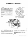
GENERAL
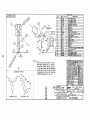
COMPONENT LOCATION
There are two generator designs used on the UR
series. They are basically the same except for the
method of field excitation.
To gain access to generator, remove grille section
below control box.
,
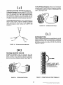
1 . Exciter-regulator chassis assembly VR22 mounts
on the rear portion of the generator; SCR’s
(silicon controlled rectifiers) and diodes are easily accessible for testing. See Figures 1-3.
2. On static-excited generators, brush”es attach to
the brush rig inside of end bell housing; inspect
through large access holes in the end bell. See
Figure 1.
3. On brushless models, rotating exciter assembly
mounts directly behind exciter-regulator chassis
assembly with all diodes accessible for servicing.
See Figure 2.
4. Voltage-regulator PC Board VR21 (Printed Circuit Board) mounts inside the control box on the
rear panel (left side); turn 114 turn fasteners o,n
front of control box to gain access. See Figure 4.
The Static Exciter (brush type) design uses a brush
rig and collector rings for field excitation. This design
was used on some of the earlier models within the
range of 25 KW - 90 KW.
The Brushlessdesign uses a rotating rectifier exciter
assembly in place of the brush rig for field excitation.
The brushless design is standard on all models from
25 KW - 175 KW.
Unless otherwise specified, the tests in this section apply to both
designs.
V R -22
EXCITER REGULATOR
CHASSIS ASSEMBLY
END B ELL
AC
-
L
STATOR
OUTPUT
‘\--
208-240
VOLTS
AC
RESIDUAL MAGNETISM
IN R O T O R S T A R T S
PROCESS
,
&
~
SOLID STATE
4 N D VOLTAGE
REGULATOR
.
.TOR
R E V O L V I N G FIELD
OVERSPEED S W I T C H
QENERATOR E N D VIEW (QRILLE REMOVED)
EXCITATION S C H E M A T I C
FIGURE 1. STATIC EXCITER DESIGN
5
Redistribution or publication of this document,
by any means, is strictly prohibited.
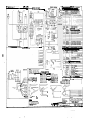
A LT E R N A T 0 R
EXClT E R- REGULATO R
CHASSIS ASSEMBLY
iTATOR
FENDBELL
.
208-240
VOLTS
AC
EXCITER
CIRCUIT
I
BREAKER
FIELD
w
EXCITER
ARMATURE
VOLTAGE
R E(3U L A T O R
I
QENERATOR E N D VIEW (QRILLE REMOVED)
~~~
EXCITATION S C H E M A T I C
,
!
t
CHECK T H E S E S I N G L E L E A D RECTIFIERS
ACCORDING T O P R O C E D U R E "E"
FIGURE 3.
TOP VIEW OF EXCITER-REGULATOR CHASSIS ASSEMBLY
!
V R21
VOLTAGE REGULATOR
P R I N T E D C I R C U I T BOARD
i
'FIGURE 4.
VOLTAGE REGULATOR PRINTED CIRCUIT BOARD LOCATION
6 ,
Redistribution or publication of this document,
by any means, is strictly prohibited.
VISUAL INSPECTION
I
I
Before proceeding with the troubleshooting on the
following pages, a few simple checks can be made
which could directly indicate the cause'of trouble.
1. Always be sure that connection of generator
leads is correct. Whenever leads are reconnected
for a different voltage, check the output with an
independent voltmeter. Do not use the control
panel meter since it could indicate that the
voltage is correct even i f connection is wrong.
2. Visually inspect the voltage regulator printed
circuit board assembly (VR21) in the control box
for burned components, broken wires, loose
connections, dust, dirt or moisture. If dirty, clean
with a suitable solvent and compressed air.
3. Visually inspect the exciter-regulator chassis
assembly (VR22) for burned components, broken
wires, loose connections, carbon tracks caused
by arcing between parts or between parts and
ground. Also check for shorted paths between
terminals caused by dust, dirt and moisture.
4. Large banks of SCR (Silicon Controlled Rectifier)
regulated loads can cause the generator voltage
to increase as load is applied. If such loads exist,
and the voltage increased more than 5 or lo%,
consult the factory; an additional filter is available
for the regulator circuit to correct the situation.
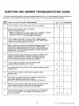
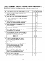
THE QUESTION AND ANSWER TROUBLESHOOTING GUIDES BEGINNING
ON PAGE 8 GIVE A STEP-BY-STEP PROCEDURE FOR CHECKING THE
GENERATOR. THE FLOW-CHART TROUBLESHOOTING GUIDES ARE
GIVEN AS A GENERAL GUIDE TO RESOLVE VARIOUS GENERATOR
PROBLEMS. ALL CHARTS REFER TO PROCEDURESSHOWN AT THE END
OF THIS SECTION.
.
PRIOR TO ANY TROUBLESHOOTING, CHECK ALL MODIFICATIONS,
REPAIRS, REPLACEMENTS, ETC.. PERFORMED SINCE LAST SATISFACTORY OPERATION OF SET.
7
Redistribution or publication of this document,
by any means, is strictly prohibited.
QUESTION AND ANSWER TROUBLESHOOTING GUIDE
To correct a particular problem, answer the question either “yes” or “no,” then proceed to the next step
in
. given
whichever column question was answered. Procedures A thru P follow the troubleshooting guide.
‘LiM
I
~~
TABLE A. NO OUTPUT VOLTAGE
- ENGINE RUNNING
YES
1.
Is circuit breaker on the meter panel in the “on” position?
2.
Switch circuit breaker to the “on” position.
Does AC voltage build up?
NOTE: If voltage builds up, but is high, low or unstable, or causes
the circuit breaker on the meter panel to trip, refer to
Table “B,” “C’ or “D” of the troubleshooting guide.
NO
PROCEDURt
‘
1
I
3
I
I
3.
Is AC voltage at terminals 1 and 2, on VR21 voltage regulator
printed circuit board and at terminals 9 and 10 on VR22 exciterregulator chassis assembly 5 to 10 volts?
~~
4.
5.
6.
7.
9.
10.
11.
C
Check continuity of wires and connections between terminal 1 on
VR21 printed circuit board and terminal 9 on VR22 chassis
assembly; and between terminal 2 on VR21 printed circuit board .
and terminal 10 on VR22 chassis assembly. Is there continuity
between these connections?
10
Check for broken wires and loose connections on VR22 exciterregulator chassis assembly. Replace or repair any that are
defective and clean all dust, dirt and other foreign material
from the assembly. Does AC voltage now build up?
6
Is DC voltage at terminals 4 and 5 on VR22 exciterregulator chassis assembly 5 to 10 volts?
I
l3
,
Are diodes CR1, CR2 and CR3 on VR22 exciter-regulator chassis
assembly OK?
8.
5
~~
Are SCR’s Q4 and Q5 on VR22 exciter-regulator chassis
assembly OK?
8
F
9
The trouble is probably caused by a defective component on
the voltage regulator printed circuit board.
REPLACE VR21 PRINTED CIRCUIT BOARD (see Figure 4).
With the circuit breaker on the meter panel in the “off” position,
is AC voltage at terminals 62 and 63 (on terminal board
TB21 on the left side of control box) 5 to 10 volts?
With the circuit breaker on the meter panel in the “off” position,
flash the exciter field. Is AC voltage at terminals 62 and 63
now 5 to 10 volts?
11
12
13
B
8
Redistribution or publication of this document,
by any means, is strictly prohibited.
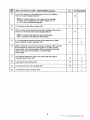
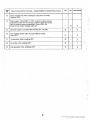
TABLE A. NO OUTPUT VOLTAGE - ENGINE RUNNING (continued)
YES
NO
PROCEDURE
Turn circuit breaker on the meter panel t o the “on” position.
Does AC output voltage build up?
NOTE: If voltage builds up, but is high, low or unstable,
or causes circuit breakerto trip. refer to table “B.” “C”
or “D” of this troubleshooting guide.
17
Is brushless exciter stator winding OK?
With a jumper wire connected across the terminals of the circuit
breaker on the meter panel, does voltage build up?
NOTE: If voltage does build up, the circuit breaker
CB21 is defective and MUST BE REPLACED.
~
~-
Is 11 commutating reactor mounted on the back side of VR22
exciter-regulator chassis assembly OK?
D
Check continuity of wires and connections between 1821 terminal
62 on left side of control box and terminal 1 on VR21 printed
circuit board. Also check between TB21 terminal 63 on the left
side of control box and terminal 2 on VR21 printed
circuit board.
Are rotating diodes CR1,CR2, CR3,CR4,CR5 and CR6 on
brushless exciter rotor OK?
18
E
Is generator field winding OK?
19
G
Is brushless exciter rotor winding OK?
20
J
H
Are generator stator windings OK?
9
Redistribution or publication of this document,
by any means, is strictly prohibited.
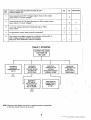
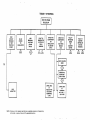
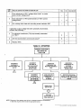
TABLE A. SYNOPSIS
BRUSHES
OR LOOSE
BRUSH
CB2l
CIRCUIT
BREAKER
ON METER
PANEL I N
"OFF"
POSITION
(RESET)
++
LOSS OF
RESIDUAL
VOLTAGE
(FLASH
NO AC
POWER
TO
EXCITER
FIELD)
FAULT I N
GENERATOR
FIELD
WINDING
DEFECTIVE
COMPONENT
ON
REGULATOR
PC BOARD
(VR21)
COMPONENT
VOLTAGE
REGULATOR
CHASSIS
ASSEMBLY
nI
-I-
DEFECTIVE
CIRCUIT
BREAKER
ON METER
PANEL
A
-I
BUILD-UP
RELAY, K1
Q4 OR Q5
1
CR8 OR CR9
OPEN
DEFECTIVE
DIODE CR1
R l , R2 OR R3
/E\
OPEN
OPEN LEAD
PC BOARD
NOTE: Whenever a letter appears near the box, a separate procedure,
corresponding to that letter, is given at the end of this section.
*
TERM"ALS
1 OR 2
- Check SCR's, Q4 and Q5 on VR22 voltage regulator chassis assembly
and replace (if defective) before repairing or replacing VR21 voltage
regulator printed circuit board.
**
-
Static excited generators only.
__
...
.
-..
FAULTY
ROTATlNG
DIODE
ON
BRUSHLESS
EXCITER
P
I
TERMINAL
1, 2,4,5
FAULT IN
BRUSHLESS
EXCITER
ROTOR OR
STATOR
WINDING
i
L
t
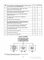
TABLE B. OUTPUT VOLTAGE BUILDS UP BUT IS UNSTABLE ENGINE RUNNING OK
ITEM
NO.
I
I I
2.
Does adjustment of R26* (damping control pot) on VR21 printed
circuit board result in stable generator voltage?
1 8
I
I
:
Are there any loose or broken wires or connections at VR21
printed circuit board terminals?
I
3.
I
The trouble is probably caused by a defective component on
VR21 voltage regulator printed circuit board.
REPLACE VR21 PRINTED CIRCUIT BOARD (see Figure 4).
YES
NO
PROCEDURE
7:
i
I
-
R26 is used on brushless generators only.
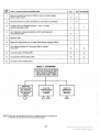
TABLE B. SYNOPSIS
!
UNSTABLE OUTPUT
VOLTAGE
DEFECTIVE COMPONENT
ON (VR21) VOLTAGE
REGULATOR PRINTED
CIRCUIT BOARD
BROKEN WIRES OR
LOOSE CONNECTIONS
AT (VR21) VOLTAGE
REGULATOR PRINTED
CIRCUIT BOARD
TERMINALS
INCORRECT SETTING
OF R26 POT ON (VR21)
PRINTED CIRCUIT
BOARD (BRUSHLESS ONLY)
I
C6. C7, R14 OR
R1S OPEN
C11, C12, R27 OR
R28 OPEN
NOTE: Whenever a letter appears near the box, a separate procedure, corresponding
to that letter, is given at the end of this section.
Redistribution or publication of this document,
by any means, is strictly prohibited.
F
-
TABLE C. OUTPUT BUILDS UP BUT IS HIGH OR LOW
ENGINE RUNNING OK
-
YES
NO
PROCEDURE
Does adjustment of R21 "Voltage Adjust" knob on the meter
panel result in correct voltage?
-
2
Does adjustment of R l b potentiometer on VR21 printed circuit
board result in correct voltage?
-
3
P
Is correct voltage reference transformer tap on TB21
being used?
4
-
L
Are generator output leads properly connected?
5
-
L
I
-
5.
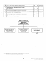
TABLE C. SYNOPSIS
TOO HIGH O R
I
I
INCORRECT
REFERENCE
TRANSFORMER TAP
ON T21
INCORRECT
SETTING OF
VOLTAGE ADJUST
POT (R21) ON
METER PANEL
I
INCORRECT
SETTING OF
VOLTAGE ADJUST
POT (R18) ON
VR21 PC BOARD
I
I
I
DEFECTIVE
COMPONENT ON
DEFECTIVE
COMPONENT ON
REGULATOR CHASSIS
ASSEMBLY (VR22)
REGULATOR PC
BOARD (VR21)
.
CONNECTION AT
TERMINALS 3 , 4 , .
I
I
!
.I
-.
. .
..
I
NOTE Whenever a letter appears near the box, a separate procedure, corresponding
to that letter, is given at the end of this section.
12
Redistribution or publication of this document,
by any means, is strictly prohibited.
I
NO:
ITEM
TABLE D. GENERATOR VOLTAGE BUILDS UP BUT CAUSES THE CIRCUIT BREAKER
ON CONTROL PANEL TO TRIP. ENGINE RUNNING OK.
Does AC output voltage build up to 150% or more of rated
voltage before CB21 circuit breaker trips?
1,
. Are
2.
there any loose or broken terminals or connections at VR21
voltage regulator printed circuit board terminals?
3.
Is diode CR3 on center heat sink of VR22 exciter-regulator
chassis assembly OK?
4.
Are voltage regulator transformer (T21) windings and
connections OK?
~
~
5.
Are stator leads connected properly?
6.
The trouble is probably caused by a defective component on
VR21 voltage regulator printed circuit board. REPLACE VR21
PRINTED CIRCUIT BOARD (see Figure 4).
I
Does AC output voltage build up to rated voltage or less
before tripping CB21 circuit breaker on meter panel?
Are rotating diodes CR1, CR2, CR3, CR4, CR5 and CR6 on
brushless exciter rotor OK?
8.
9.
.
Is brushless exciter stator winding OK?
10..
Is generator field winding OK?
11.
Is brushless exciter rotor winding OK?
DEFECTIVE
ROTATING DIODE
CR1, CR2, CR3,
CR4, CR5 OR CR6
ON EXCITER
ROTOR
l-l
FAULT IN
EXCITER ROTOR
OR STATOR
WINDING
FAULT IN
GENERATOR
MAIN FIELD
WINDING
A
NOTE: Whenever a letter appears near the box, a separate procedure, corresponding
to that letter, is given at the end of this section.
13
Redistribution or publication of this document,
by any means, is strictly prohibited.
ITEM
TABLE E. UNBALANCED GENERATOR TERMINAL VOLTAGE
-. NO. -
YES
_________
~~
~
2.
Are generator leads properly connected and/or grounded?
3
-
3.
Is continuity of generator stator windings OK?
-
-
4.
*
I'
,
Check for ground faults in load.
ji
H
I 51--1
1-14
Is grounding procedure of generator and load correct?
~~~
5.
PROCEDURE
I*141
Remove load from 'generator terminals. Are genefator'terminal
voltages still unbalanced?
1..
NO
I
NOTE: Unbalanced voltages of up to 5 percent will occur if unbalanced loads
are applied to the generator terminals.
\
TABLE
E. SYNOPSIS
UNBALANCED
TERMINAL VOLTAGES
*
INCORRECT RECONNECTION
OR GROUNDING OF
GENERATOR LEADS
INCORRECT GROUNDING
OF LOAD OR GROUND
FAULT IN LOAD
I
'
FAULTY GENERATOR
STATOR WINDING
,
t
NOTE: Whenever a letter appears near the box, a separate procedure,
corresponding to that letter, is given at the end of this section.
14
Redistribution or publication of this document,
by any means, is strictly prohibited.
TABLE E. SYNOPSIS
I
VOLTAGE 150%
[ ; I
I
MORE THAN RATED
I
rI
1
DEFECTIVE COMPONENT
ON VOLTAGE
REGULATOR CHASSIS
ASSEMBLY (VR22)
DEFECTIVE COMPONENT
ON VOLTAGE
REGULATOfi PRINTED
CIRCUIT BOARD (VR21)
I
OPEN TRANSFORMER
(T21) WINDING
OPEN WIRE OR
CONNECTION AT
VOLTAGE REGULATOR
CHASSIS ASSEMBLY
(VR22)
TERMINALS 4,5 OR 6
OPEN WIRE OR
CONNECTION AT
PRINTED CIRCUIT
BOARD (VR21)
TERMINALS 5,6, 9,10,
11 OR 12
CYCLING
BUILD-UP *
1
OPEN LEAD AT
(VR21) PRINTED CIRCUIT
BOARD TERMINALS
1, 2, 5, 7 OR 8
OPEN IN R21
VOLTAGE ADJUST POT
ON METER PANEL
I
DEFECTIVE COMPONENT
ON VR21 PRINTED
CIRCUIT BOARD
L
<
OPEN IN R18
VOLTAGE ADJUST POT
ON VR21 PRINTED
CIRCUIT BOARD
NOTE Whenever a letter appears near the box, a separate procedure,
corresponding to that letter, is given at the end of this section.
*
-
Generator voltage builds up. then collapses. builds up. etc.
Redistribution or publication of this document,
by any means, is strictly prohibited.
I
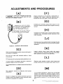
ADJUSTMENTS AND PROCEDURES
BRUSHES
ment. Do not use a substitute brush that may look
identical but may have entirely different electrical
characteristics. Be sure to install the brush SO that the
short side of its taper is toward the spring and its
bracket. See Figures 5 and 6.
When brushes wear to approximately 5/8 inch or
when wear extends into the stamped Onan part
number, replace brushes. Do not attempt to remove
the brush without first removing its spring and
brackets. Never bend a spring back over its bracket doing so will put a kink in it and require its replace-
i
I N S T A L L B R U S H E S W I T H BEVELED
TOP S L A N T I N G D O W N TOWARD
S P R I N G HOLDER-,
REPLACE BEFORE
BRUSH WEARS
TO THIS POINT
TO REMOVE BRUSH
SPRING,PRESS
SPRl NG HOLDER
DOWN A N D OUT A S
SHOWN IN BROKEN
LINES.
FIGURE 5.
FIGURE 6.
BRUSH REPLACEMENT
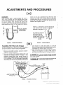
FLASHING THE FIELD (No Voltage)
1
.
.
If output voltage will not build up, it may be necessary '.
to flash the field to restore residual masnetism.
1. Remove end grille to obtain access to'exciterregulator chassis assembly:.
2. Use a six volt dry cell (lantern) battery with a 12
amp 300 volt diode as shown in' Figure 7. This
prevents current flow from exciter circuit to
battery when voltage builds up. If a lantern battery
is not available, a 12 volt automotive (generator
set) battery can be used by installing a 20-ohm 2
.
tJ
BRUSH REMOVAL
.watt resistor in series with diode; or a 24 volt
automotive (generatorset) battery can be used by
increasing the resistor value to 40-ohms.
3. After starting the set, touch the positive (+) lead to
TB5 and the negative (-) lead to TB4; hold on
terminals just long enough forvoltage to build up.
'
'
Do not keep excitation circuitry connected
longer than 5-seconds or damage may occur
to the exciter regulator.
Be cautiouswhen working on agenerator that
is running. High voltages aye present.
CHASSIS ASS
T O BUILD UP.
FIGURE 7. FLASHING THE FIELD
16
Redistribution or publication of this document,
by any means, is strictly prohibited.
I
Resistance between coils (e.g., 1-4) or from any
terminai to reactor frame should be infinity.
CCI
NO AC POWER TO EXCITER
If any of the above conditions are not met, install a
new reactor.
Residual should be checked before the circuit breaker; the best
place to check it is at the five leads 61 through 65 coming directly
out of the stator. The combinationof leadsshouldbechosen by the
wiring configuration of the stator, Le., 120/240 Delta, 120/208
ParallelWye. 277/430Series Wye. After checking residual,proceed
to VR21 PC board arid then check the circuit breaker CB21.
TESTING DIODES
If residual voltage is present, check AC voltage at
terminals 1 and 2 on VR21 voltage regulator printed
circuit board. Voltage should be 5-10 volts. The AC
voltage at terminals 9 and 10 on VR22 exciterregulator chassis assembly should be the same (5 to
10 volts). If not, check continuity between these
points. If voltage is low, check L1 reactor.
On both brushless and brush type generators. three
diodes mount on the center heat sink of the exciterregulator chassis assembly. They are labeled CR1,
CR2 and CR3 as shown in Figure 3. On brushless
generators, six diodes mount on the rotating exciter
assembly as shown in Figure 2. These six diodes are
labeled CR1. CR2, CR3, CR4, CR5 and CR6. Test
diodes as follows:
1. Disconnect one diode at a time. Test that diode
and reconnect lead before proceeding to the next
one.
2. Use an accurate ohmmeter to check the
resistance of the diode. Connect one lead to the
top of the diode and the other lead to the heat
sink. Observe reading.
3. Now reverse leads and again observe reading. A
good diode should have a higher reading in one
direction than the other. I f both readingsare high,
or if both readings are low, diode is defective and
must be replaced with a new, identical part.
TESTING L1 REACTOR
The L1 reactor mounts on the rear of VR22 exciterregulator chassis assembly. Terminals are marked 1,
2, 3 and 4.
3
h
4
Coils 1-2 and 3-4 are wound on the same iron core.
Resistance between 1-2 and 3-4 should be .0544 and
.0614-ohms f 1O0/o respectively (brush type
generators) .
m
Excessive dust or dirt on diodes and other
componentswill causeoverheatingand eventual failure. Keep these assemblies clean!
CAUTION
LEAD
LEAD
GOOD DIODE WILL HAVE HIGH RESISTANCE READING I N ONE DIRECTION
AND LOW READING WHEN OHMMETER LEADS ARE REVERSED.
FIGURE 8.
TESTING DIODES
17
Redistribution or publication of this document,
by any means, is strictly prohibited.
0 H MMETER
SHORT BETWEEN
SATE AND ANODE
CATHODE
ANODE
FIGURE 9. TESTING SCR’s
-
FIGURE 10. TESTING SCR’s
[FI
FIGURE 11. TESTING SCR’s
REPLACING
Diodes)
TESTING SCR’s
RECTIFIERS
(SCR’s
and
1. Unsolder leadwires from terminals.
2. Use proper size wrenches to hold the body while
removing the nut.
3. Push the rectifier free of its mounting hole in the
heat sink.
4. Insert new rectifier into its mounting hole in the
heat sink. Using nut and washer provided, secure
rectifier to heat ,sink.
5. .Torque the two large diodes on the center heat
sink of exciter-regulator chassis assembly to 2025 in. Ib.
6. Torque the small diode on center heat sink of
exciter-regulator chassis assemb.ly to 12-15 in. Ib.
7. Torque SCR’s o n outer heat sinks-to 20-25 in. Ib.
8. On brushless generators, torque diodes on
rotating exciter assembly to 15 in: Ib.
9. Solder leadwires to new rectifiers.
SCR’s mount on the outer heat sinks of the exciterregulator chassis assembly. They are labeled Q4 and
Q5 as shown in Figure 3.
1. Remove the leads from both SCR’s.
2. Determine polarity of ohmmeter leads. Connect
the ohmmeter leads to the anode and cathode as
shpwn in Figure 9. Use the high scale on the
ohmmeter. The resistance should be 1 megohm
or greater.
The cathode is the longer lead, the gate is the shorter lead. The
anode is the threaded stud.
3. Reverse the leads as shown in Figure 10. The
resistance again should be 1 megohm or greater.
4. With the leads connected as in Step 3, and using
the low scale on the ohmmeter, short the gate to
the anode as shown in Figure 11. The resistance
should drop to a low value.
5. Remove the short between the anode and the
gate. The resistance should remain at the same
low value.
Use a 40 watt soldering iron. Hold a
needlenose pliers between rectifier and
soldering point to prevent destructive heating. Excessive heat on
these components will destroy them.
18
Redistribution or publication of this document,
by any means, is strictly prohibited.
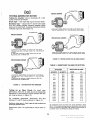
TESTING GENERATOR ROTOR
Testing for Grounds: Use an ohmmeter (R x 100
scale'); measure as follows:
Brush Type - from each slip ring to the rotor shaft.
Brushless Type - disconnect F1 and F2 rotor leads
from the rotating diodes; measure between either
lead and the rotor shaft. A reading of less than infinity
indicates a ground. See Figure 12.
C O N T A C T ONE P R O D TO ONE SLIP RING AND
T H E OTHER P R O D T O T H E SECOND SLIP RING.
0 HM M ETER
BRUSH DESIGN
C O N T A C T ONE P R O D TO EACH O F THE SLIP
RINGS AND T H E OTHER PROD T O THE R O T O R
SHAFT.
IF ROTOR IS G O O D THERE S H O U L D BE NO
READING O N OHMMETER.
C O N T A C T O N E P R O D TO ONE FIELD LEAD AND
T H E SECOND P R O D T O THE OTHER FIELD LEAD
OHMMETER
FIGURE 13. TESTING ROTOR FOR AN OPEN CIRCUIT
TABLE 3. RESISTANCE VALUES FOR ROTORS
KW RATING
I
I
1
50HERTZ
25.0
C O N T A C T ONE P R O D TO EACH O F THE FIELD
L E A D S AND T H E OTHER PROD T O THE ROTOR
SHAFT.
IF ROTOR IS G O O D ' T H E R E S H O U L D BE N O
READING ON OHMMETER
FIGURE 12.
37.0
40.0
45.0
50.0
55.0
60.0
70.0
75.0
80.0
95.0
1 10.0
1 1 5.0
125.0
140.0
145.0
TESTING ROTOR FOR GROUNDS
Testing for an Open Circuit: On brush type
generators, check for an open circuit by measuring
resistance in the windings. Check between the two
slip rings as shown in Figure 13.
On brushless generators, disconnect and test
between F1 and F2 leads as shown in Figure 13.
Resistance values given in Table 3 apply to both brushless and
brush type generator rotors.
60HERTZ
30.0
40.0
45.0
50.0
55.0
55.0
60.0
65.0
75.0
85.0
90.0
100.0
115.0
125.0
140.0
150.0
170.0
175.0
RESISTANCE IN OHMS
FROM
3.32
2.49
2.49
2.49
2.76
2.76
3.02
3.02
3.16
2.76
2.76
3.19
3.26
3.96
3.96
3.09
3.42
3.42
TO
,
4.06
3.05
3.05
3.05
3.38
3.38
3.70
3.70
3.86
3.38
3.38
3.90
3.99
4.40
4.40
3.78
4.18
4.18
All resistances should be within the values specified at 20°C
(68"F). This includes readings between slip rings on static excited
rotors and between field leads (with rectifiers disconnected) on
brushless rotors. Use Wheatstone Bridge for testing.
Replace the rotor if it is grounded or has an open or
short.
19
Redistribution or publication of this document,
by any means, is strictly prohibited.
TESTING GENERATOR STATOR
FROM
KELVIN
BRIDGE
Testing for Grounds: Connect all stator output leads
(Tl-T12) together. Use an ohmmeter set on the R x
100 scale and measure the insulation resistance
between these windings and the stator frame. A
reading of less than infinity indicates a ground. Field
circuit breaker can be either “ON” or “OFF”.
!
Testing for Shorts: To check for shorts between
individual windings first refer to Figure 18 to determine individual coil lead wires (Tl-T4, T7-Tl0, etc.)
Connect one lead of an ohmmeter (RX100 scale) to
one of the stator windings and the other ohmmeter
lead to all other stator leads connected together. A
reading of less than infinity indicates a short. Repeat
until all stator coils have been tested in this manner.
i
Coil Resistances: Measure resistance of windings
using a Wheatstone or Kelvin bridge meter. SeeTable
4 and Figure 14. If any windings are shorted, open or
grounded, replace the stator assembly. Before
replacing the assembly, check the leads for broken
wires or damaged insulation.
FIGURE 14. TESTING STATOR WINDINGS
Stator output leads T4, T7, T8, T9 and T10 are interconnected
(within the stator) to five stranded (#lo aircraft) control wires.
These wires are labeled 4,7,8,9 and 10 respectively and terminate
at TB2.1 (terminals 61-65).
TABLE 4. .RESISTANCE VALUES
FOR STATORS*
VOLTAGE CODE (Resistance in Ohms)
KW R TlNG
I
I
50 HERTZ
6O.HERTZ
25.0
30.0
40.0
45.0
50.0
55.0
’
37.0
40.0
’
,450
50.0
55.0
60.0
70.0
75.0
80.0
95.0
110.0
115.0
125.0
140.0
145.0
55.0
60.0
65.0
75.0
85;O
90.0
100.0
115.0
125.0
140.0
150.0
170.0
175.0
I
15
0.116 0.047 0.047 0.047 0.028 0.038 0.028 0.028 0.022 0.019 0.019 0.015 0.012 0.009 0.009 0.0075 0.0059 0.0059 -
I
9x
3
0.425 - 0.520
0.141
0.058
0.058
0.058
0.035
0.047
0.035
0.035
0.027
0.024
0.024
0.018
0.015
0.011
0:Oll
0.0092
0.0072
0.0072
.
0.193
0.193
-
0.236
0.236.
.
0.052
0.047
0.047
-
0.063
0.058
0.058
0.156 - 0.191
0.113 - 0.138
0.113 - 0.138
-6.089 - 0.108
0.072 - 0.089
0.072 - 0.089
0.054 - 0.067
0.045 - 0.055
0.039 - 0.048
0.039 - 0.048’
0.027 - 0.033
0.018 - 0.023
0.018 - 0.023
AI: r’(?sislancesshould be within the values shown at 20°C (68’ F).
Use an accurate instrument such as a Kelvin Bridge for this test.
Test between the following coil leads:
T1-T4
17-T 10
T3-T6
T9-Tl2
T2-T5
T8-Tl1
20
Redistribution or publication of this document,
by any means, is strictly prohibited.
.
Testing Winding Resistance: Measure coil resistance
between leads F1 and F2 with an ohmmeter (scale Rx
1). Resistance should be17.82 to 21.78ohmsat 20°C
(68°F). See Figure 16A.
IJI
TESTING EXCITER ROTOR (Armature)
!
Testing for Grounds: Remove diodes CR1, CR2, CR3,
CR4, CR5, and CR6 from diode heat sink assemblies.
Using an ohmmeter (R x 100 scale) measure insulation resistance between any of the leads and the
laminations (exclude the diodes from the test circuit).
A reading of less than infinity indicates a ground.
Testing Winding Resistance: Using a Wheatstone or
Kelvin bridge meter, measure resistance between
leads pairs T1-T2, T2-T3 and Ti-13. Resistance
should be 0.464 to 0.567 ohms at 20°C (68°F). See
Figure 15.
FIGURE 16A. TESTING EXCITER FIELD
RECONNECTION
Figure 18 shows reconnection possibilities forthe UR
series generators. When reconnecting for a different
voltage, be sure to also reconnect lead from terminal
63 (inside control box) to either H3, H4, H50rH6.See
Figures 17 and 18.
FIGURE 15. TESTING EXCITER ARMATURE
TESTING EXCITER STATOR
Testing for Grounds: Using an ohmmeter (R x 100
scale), measure the insulation resistance between
either lead F1 or F2 and the laminations. A reading of
less than infinity indicates a ground. See Figure 16.
(W12 WIRE)
CONNECT LOOSE W I R E
F R O M TERMINAL #63
T O E I T H E R H3.H4.H5 O R
H6 D E P E N D I N G ' O N
V O L T A G E SELECTED.
FIGURE 17. CONNECTING LEAD FROM TERMINAL 63
FIGURE 16. TESTING EXCITER FIELD
21
Redistribution or publication of this document,
by any means, is strictly prohibited.
E,
NAMEPLATE VOLTAGE CODE 9 X
N A M E P L A T E VOLTAGE CODE 3
T1
+
CONNECT L E A D FROM
TERMINAL 63 TO H5
CONNECT LEAD FROM
TERMINAL 63 10 H5
THIS D I A G R A M APPLIES TO 12 LEAD GENERATORS ONLY
GENERATOR CONNECTION W I R I N G D I A G R A M
8'l
SCHEMATIC
DIAGRAM
(WITH
CURRENT TRANSFORMERS WHEN USED)
/
11
LO
12
i
LO
IS 120/240
1 60
H5
115/230
1 50
H6
116220 1 5 0
H6
115
TI0
77
75
L2
LO
15 120/140 3 60
115/230
3 50
19
T 1 12 16 111 18112 14
L1
1s 17 T 3
110
L3
12
H5
H6
i1S
T10
11
16 17
12
L1
LO
111 14 T 8
'73
L2
T12 T5 19
13
I
I
W
5
'7:
13
1
, .
4
16
I5
111
110 112"
LO
l7
12 T 8
13 19
L1
12
13
T I T 7 T4
12 T 8 15
T3T9 1
111
710
711
LO
79
L3
1101lt T12
98C2193
FIGURE 18. RECONNECTION DIAGRAM
22
Redistribution or publication of this document,
by any means, is strictly prohibited.
t
i.
1
I
il
:!
. .
SENSITIVITY REFERENCE CIRCUIT
UR series voltage regulators (VR21) can be set to
either frequency sensitive or non-frequency sensitive
reference. With a frequency sensitive reference, the
output voltage of the generator will decrease in
proportion to the frequency (Le., prime moverspeed).
This decrease in output voltage will reduce the load
on the prime mover, permitting it to return to rated
voltage and frequency when overload is removed. A
temporary overload with a non-frequency sensitive
reference could cause a prime mover to reduce
speed, then would require a further 50% to 60% load
reduction to allow it to return to rated speed.
This reference change is accomplished by soldering
wire W1 to terminal E l for frequency sensitivity or to
terminal E2 for non-frequency sensitive reference.
See Figure 19.
Unless requested otherwise by purchaser, Onan sets are connected at the factory to a frequency sensitive reference.
TOP SIDE OF.
VOLTAGE
REGULATOR
WHENMOUNTED
UNSOLDER THIS WIRE
FROM E I AND CONNECT
TO E2 FOR A NONFREQUENCY SENSITIVE
VOLTAGE REFERENCE
CIRCUIT.
-
FIGURE 19. VR21 PRINTED CIRCUIT BOARD
23
Redistribution or publication of this document,
by any means, is strictly prohibited.
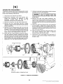
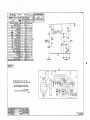
GENERATOR DISASSEMBLY
,
If generator testing determines that generator needs
repair, remove and disassemble according to Figure
'20 and the following instructions:
7. Using an overhead hoist and sling, slide the stator
assembly off the rotor assembly.
Disconnect and remove load wires.
Disconnect leadwires from the control box.
Check wire markings for legibility to ease
assembly. Arrange leads so they can be
withdrawn easily from the control box.
Remove front grille (14) and sheet metal work.
Remove the four capscrews securing voltage
regulator chassis (23) to end bell (9) and remove
chassis assembly.
Remove the centrifugal switch (8) from end bell
and rotor shaft. On static excited models, slip the
brushes (7) and brush springs (6) from brush rig
(5) - it is not necessary to disconnect the brush
leads unless brush replacement is required.
Block the rear of the engine in place by supporting the flywheel housing. Remove the narrow
generator band (10). Remove the large capscrews
securing generator mounting pad (11) to the skid
base. Remove the capscrews securing the stator
assembly (4) to the engine flywheel housing.
8. Remove end bell from stator assembly; disconnect and remove brush rig from end bell on
static excited generators. On brushless models,
remove exciter field (24) from end bell assembly if
required.
9. Attach the hoist and sling to the rotor assembly
(1) and apply a slight lift to support the rotor.
Remove the capscrews securing the flexibledrive
coupling (13) to the engine flywheel and remove
rotor from the engine.
10. Remove bearing capscrew (18) and washer (17)
and remove bearing from shaft. If required,
remove blower (2) from the rotor.
11. Disconnect rotor field leads from heat sinks F1
and F2 on the exciter armature. Remove exciter
armature (25).
E z 3
Use care not to damage the brush rig (or
exciter on brushless models) while
removing the stator. Do not allow the stator to rest on rotor
during removal.
CAUT,ON
'
9
23
L
A
/
BRUSHLESS G E N E R A T O R
FIGURE 20.
GENERATOR DISASSEMBLY
24
Redistribution or publication of this document,
by any means, is strictly prohibited.
GENERATORASSEMBLY
Generator assembly is the reverse of disassembly
procedure:
1. Always replace bearing with a new one; apply a
layer of grease on end bell bearing hole before
inserting bearing.
2. Torque bearing capscrew to 60-70 Ib. ft.
3. Torque drive disc-to-rotor capscrews to 200-240
Ib. ft.
4. Torque drive disc-to-flywheel capscrews to 45-50
Ib. ft.
5. Torque generator through-stud nuts to 30-40 Ib.
ft.
6. Refer to Purrs Curu/o,y for replaceable parts and
assemblies. Refer to Wiring Diuputii for
reassembly.
[PI
VOLTAGE ADJUSTMENT
After replacement, voltage regulator (VR21) adjustment is performed as follows (see Figure 21):
1. Center the voltage adjust knob so pointer is in a
vertical position.
2. Open meter panel doors. Start unit.
3. Using a screwdriver, turn R18 potentiometer on
printed circuit board VR21 counterclockwise to
increase the voltage or clockwise to decrease the
voltage. Observe voltmeter on meter panel while
making adjustment. Set voltage with no load
connected to generator. (Example: For a 120/240
volt connection, set at no-load voltage or approximately 246 volts.)
If voltage is unstable or tends to hunt, turn R26
potentiometer on VR21 in the direction shown on
printed circuit board to increase voltage sensitivity.
I
ADJUST R26
HERE
\
ADJUST R 18
HERE
FIGURE 21. ADJUSTING VOLTAGE ON VR21
25
Redistribution or publication of this document,
by any means, is strictly prohibited.
- SECTION II
GENERATOR
GENERAL
,
,
Generators discussed in this section are brushless
type only. The difference between these and the
generators in Section I is in the VR22 diode assembly
and the commutating reactor. These have been
removed from the generator end bell and relocated in
the control panel. The diodes are now encapsulated
within a hermetically sealed block, therefore if any
diode or silicon controlled rectifier fails, the entire
unit has to be replaced. See Figure27fordetailsof the
rectifier assembly (CR21) and Figure 25 for the
reactor (L21).
Principles of operation and method of excitation
remain unchanged from the units described in Section I.
Refer to Table 1 for generators to which this section
. applies.
ROTATING EXCITER
WITH RECTIFIERS
ov‘ERSPEED SWITCH
QENERATOR END VIEW (QRILLE REMOVED)
FIGURE 22.
ROTATING RECTIFIER ASSEMBLY
VR2‘ VOLTAGE
RE GU LATO R
121 REACTOR
FIGURE 23.
/
\
CR2 I
SCR BRIDGE
SCR BRIDGE AND REACTOR LOCATION
:TROUBLESHOOTING
ing the generator. To use the guides, answer the
questions either “yes” or “no” then proceed to the
next step given in whichever column is indicated.
Use the following troubleshooting charts and
procedures to locate malfunctions in the generating
system. Section 11 also references procedures A thru
P of Section 1.
When using block diagrams, a letter with a triangle
indicates a procedure in Generator - Section 1. A letter
within a diamond indicates a procedure in GeneratorSection II.
The question and answer troubleshooting guides
which follow give a step-by-step procedure for check-
26
Redistribution or publication of this document,
by any means, is strictly prohibited.
QUESTION AND ANSWER TROUBLESHOOTING GUIDE$
To correct a particular problem, answer the question either “yes” or “no,” then proceed to the next step given in
whichever column question was answered. Procedures R thru P follow the troubleshooting guide.
ITEM
NO.
F. N O AC OUTPUT VOLTAGE - ENGINE RUNNING AT RATED RPM
YES
NO
Is Exciter Circuit Breaker (CB21) on the meter panel
in the “ON” position?
3
2
Switch CB21 to “ON” position. Does AC voltage build up?
-
3
Is A C voltage measured at terminals 1 and 2 on voltage
regulator (VR21) printed circuit board 5 to 10 volts?
6
4
Is AC voltage measured at terminals 11 and 12 on
VR21 5 to 10 volts?
5
7
5.
Replace reactor assembly (L21).
-
-
6.
Is DC voltage measured at terminals + and - on
Rectifier Bridge (CR21) 5 to 10 volts?
15
11
Shut down generator set. Check continuity through L21
coils between terminal 2 on VR21 and T8 on generator,
between terminal 1 on VR21 and T7 on generator. Is
there continuity between these connections?
VR21-2 to T8
VR21-1 to T7
14
14
10
8
If there is no continuity between VR21-1 and T7
((2621-ON) apply a shorting jumper across CB21.
Is continuity obtained?
9
10
Replace CB21.
-
-
Check for loose or broken wires on VR21, CR21, L21,
reference voltage transformer (T21), generator
bus-bars and terminal board (TB21) in control
box. Secure or repair where necessary. If
repairs have been made, restart engine.
Does AC voltage now build up?
-
14
Are diodes CR1, CR2 and CR3 on CR21 assembly good?
(See method T in procedure section for checking
diodes.) If faulty diode located, replace CR21.
12
-
T
Are SCRs 1 and 2 in CR21 good?
(See method T in procedure section for checking
diodes.) If faulty SCR’s located, replace CR21.
13
-
T
1.
2.
TABLE
PROCEDURE
NOTE If voltage builds up but is high, low or unstable,
or causes CB21 to trip, refer to table G. H or I of
troubleshooting guide.
3.
4.
7.
8.
9.
10.
12.
Redistribution or publication of this document,
by any means, is strictly prohibited.
!
;
ITEM
NO.
TABLE F. NO AC OUTPUT VOLTAGE-
YES
ENGINE RUNNING AT RATED RPM (continued)
13.
Fault probably lies with a defective component on VR21.
Replace VR21.
14.
Start engine. Place CB21 in “OFF” position. Using method
prescribed under “R” in procedure section flash the exciter
field to restore residual magnetism. Place CB21 ON.
Does the AC output voltage build up?
15.
Shut off engine. is exciter field winding (F1: F2) OK?
16
16.
Are rotating diodes CRI, through CR6 on exciter
rotor OK?
17
~~
17.
I
No
lPROCEDURE
~
Is generator stator winding OK?
18
-
.
.
18.
Is exciter rotor winding OK?
19
19.
Are generator rotor windings OK?
13
I
.
.
.
. . .
I
.
i
28
Redistribution or publication of this document,
by any means, is strictly prohibited.
TABLE F. SYNOPSIS
1
NO VOLTAGE
BUILD-UP
N
eo
SCRl OR SCRP
OPEN
,
-
DEFECTIVE
DlODECR1
CR2 OR CR3
OPEN LEAD
-
REGULATOR
PC BOARD
TERMINALS
1 OR 2
.
OPEN LEAD
AT
TERMINAL
NOTE: Whenever a letter appears near the box, a separate procedure, corresponding
to that letter, is given at the end of the, appropriate section.
. . ....
._
_.
.-
-
....
TABLE G. UNSTABLE OUTPUT
TION
I
- ENGINE RUNNING AT 1800 RPM - NO FLUCTUA-
I
1
YES
NO IPROCEDURE
I
I
I
I
I
I
Are there any loose or broken wires or connections at
VR21 terminals?
-
2
Does adjustment of R26 (damping control potentiometer)
on VR21 stabilize generator voltage?
-
3
Replace VR21.
-
-
I
P
TABLE G. SYNOPSIS
UNSTABLE OUTPUT
VOLTAGE
i
DEFECTIVE COMPONENT
ON (VR21) VOLTAGE
REGULATOR PRINTED
CIRCUIT BOARD
BROKEN WIRES OR
LOOSE CONNECTIONS
AT (VR21) VOLTAGE
REGULATOR PRINTED
CIRCUIT BOARD
TERMINALS
INCORRECT SETTING
OF R26 POT ON (VR21)
PRINTED CIRCUIT
BOARD
.
,
,
,
,
._
..
.
. ..
.-
".
1
. ..
.
I
I
NOTE: Whenever a letter appears near the box, a separate procedure, corresponding
to that letter, is given at the end of the appropriate section.
30
Redistribution or publication of this document,
by any means, is strictly prohibited.
.-
TABLE H. OUTPUT VOLTAGE TO HIGH OR LOW
&M
YES
NO
PROCEDURE
--
1.
2.
3.
Does adjustment of R21 “voltage adjust knob” on meter
panel correct voltage level?
-
2
Does adjustment of R18 potentiometer on VR21 correct
voltage level?
-
3
Are rotating diode heat sink mounting screw insulators OK?
-
-
__
P
If generator output voltage has been optionally reconnected,
consider the following -
4-
I
Is reference transformer (T21) tap correctly connected
on TB21?
1
5
5.
Are the reconnections correct and secure?
6
6.
Replace VR21.
TABLE H. SYNOPSIS
TOO HIGH OR
TOO LOW
i
I
INCORRECT
REFERENCE
TRANSFORMER TAP
ON T21
-
I
INCORRECT
SETTING OF
VOLTAGE ADJUST
POT (R21) ON
METER PANEL
1
I
DEFECTIVE
COMPONENT ON
RECTIFIER ASSEMBLY
CR21
%
/L\
I
I
r
INCORRECT
SETTING OF
VOLTAGE ADJUST
POT (R18) ON
VR21 PC BOARD
OPEN LEAD OR
CONNECTION AT
TERMINALS
G1 OR G2
DEFECTIVE
COMPONENT ON
VOLTAGE
REGULATOR PC
BOARD (VR21)
H
DEFECTIVE ROTATING
DIODE OR BAD INSULATOR
ON HEAT SINK MOUNTING
SCREW
1
OPEN IN CR1,
CR2 OR CR3
1
I
VOLTAGE
BREAKDOWN OF
SCRl ORSCR2
I
NOTE: Whenever a letter appears near the box, a separate procedure, corresponding
to that letter, is given at the end of the appropriate section.
31
Redistribution or publication of this document,
by any means, is strictly prohibited.
IiLM
TABLE 1. EXCITER CIRCUIT BREAKER TRIPS
YES
1.
Does AC output build up to 150% or more of rated voltage
before CB21 trips?
2.
Are there loose or broken terminals or connections at VRZl?
NO
PROCEDURE
Is diode CR3 (connected between + and - in CR21
rectifier assembly) OK?
Are reference voltage transformer (T21) windings and
connections O K ?
5.
Replace VR21.
6.
Does AC output build up to rated value before tripping CB21?
7.
Are rotating diodes CR1 through CR6 on exciter
rotor OK?
8.
Is exciter stator winding OK?
9.
Is generator field winding OK?
10.
Is exciter rotor winding OK?
DEFECTIVE
ROTATING DIODE
CR1, CR2, CR3,
ON, EXCITER
FAULT IN
EXCITER ROTOR
OR STATOR
WINDING
ROTOR
N O T E Whenever a letter appears near the box, a separate procedure, corresponding
to that letter, is given at the end of the appropriate section.
32
Redistribution or publication of this document,
by any means, is strictly prohibited.
YES
TABLE J. UNBALANCED GENERATOR OUTPUT VOLTAGE
-
Remove load from generator terminals. Is output
still unbalanced?
2
Are generator leads properly connected or grounded?
3
Is generator stator winding continuous?
4
Is grounding procedure of generator and load correct?
5
[
NO lPROCEDUREl
I -
Check for ground faults on load.
TABLE J. SYNOPSIS
TERMINAL VOLTAGES
!
I
INCORRECT RECONNECTION
AND/OR GROUNDING OF
GENERATOR LEADS
1
INCORRECT GROUNDING
OF LOAD OR GROUND
FAULT IN LOAD
I
I
FAULTY GENERATOR
STATOR WINDING
I
1
NOTE: Whenever a letter appears near the box, a separate procedure, corresponding
to that letter is given at the end of the appropriate section.
33
Redistribution or publication of this document,
by any means, is strictly prohibited.
TABLE J. SY NOPSlS (Continued)
I
VOLTAGE 150%
MORE THAN RATED
I
OPEN TRANSFORMER
(T21) WINDING
OPEN WIRE OR
CONNECTION AT
VR21 MODULE
TERMINALS 5, 6, 9,10,
11 OR 12
DEFECTIVE COMPONENl
ON RECTIFIER
ASSEMBLY CR21
1.
*
DlODECR3
OPEN
DEFECTIVE COMPONENl
ON VOLTAGE
REGULATOR (VR21)
MODULE
I-
BREAKDOWN OF
S C R l OR SCRP
NOTE: Whenever a letter appears near the box, a separate procedure, corresponding
to that letter, is given at the end of the appropriate section.
Malfunction occurs after warmup or voitage adjustment.
34
Redistribution or publication of this document,
by any means, is strictly prohibited.
ADJUSTMENTS AND PROCEDURES
(Applies to Section II Only)
I
FLASHING THE FIELD
If output voltage does not build up it may be
necessary to restore the residual magnetism of the
poles by flashing the field. Assembleasixvolt battery,
and diode as shown in Figure 24. If a six volt lantern
battery is not available a 12-volt (generator set
battery) or a 24-volt battery can be used, however a
20-ohm or a 40-ohm 2 watt resistor must be used in
conjunction with the 12 amp 300 V diode. Start the
generator set, touch positive lead to + on rectifier
bridge, and negative lead to the - terminal. Hold leads
on terminals just long enough for voltage to build up.
TESTING L21 REACTOR
The L21 commutating reactor mounts inside the
control box, below the VR21 Voltage Regulator.
I
The coils 1-2 and 3-4 are wound on the same core.
Resistance between 1-2 and 3-4 should be .034 ohm f
.0034 and .042 ohms .0042 respectively (brushless
units). Resistance between coils (e.g., 1/4) or from
any terminal to frame of the reactor should be icfinity
(Figure 25).
*
Do not keep excitation circuitry connected
longer than 5-seconds, or damage may occur
to the exciter regulator.
I
I2 AMP.
300 v.
I
RECTIFIER BRIDGE
FIGURE 24.
FIELD FLASHING CIRCUIT
FIGURE 25.
35
L21 REACTOR
Redistribution or publication of this document,
by any means, is strictly prohibited.
1
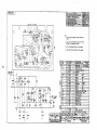
TESTING RECTIFIER BRIDGE ASSEMBLY
(CR21)
The rectifier bridge located within the control cabinet,
below the voltage regulator, contains 3 diode? CRl.
CR2. and CR3, and two silicon C O I I I I ~ I ~ rI 'IcIx~t t~l i ~
t t t~
SCR1 and SCR2. These diodes and SCR's arc cncali:;dated within a hermetically sealed block, therefore
lailurc! of any diode or SCR means the entire unit has
to bc replaced. See Figure 26.
I
A C TERMINALS ARE
GIVEN NUMERIC
DESIGNATIONS FOR
T E X T REFERENCE
ONLY. DOES NOT
APPEAR ON UNIT.
CR I
7i-
-1
I
h
CR3
-
'
I
-
CR2
FIGURE 26.
RECTIFIER ASSEMBLY
Disconnect wires from rectifier unit prior to testing.
Test unit in order shown in Table 5. Refer to Figure 27
for SCR1 and SCR2test circuit. When test is complete
and satisfactory, reconnect unit observing correct
wiring hook-up.
r---
'
6 VOLT
DRY CELL
BATTERY
FIGURE 27.
TESTING SCR
36
Redistribution or publication of this document,
by any means, is strictly prohibited.
I
NG
REMARKS
METER SCALE
CR3
Infinity
RXlOK
CR3
6- to 50-Ohms
R X l
Infinity
RXlOK
lnfinitv
RXlOK
SCR
SCRl
CR1
RX1
2CR2
Infinity
RXlOK
Infinity
R X l OK
6- to 50-Ohms
RX1
DC Voltmeter
lead
DC Voltmeter
Reading
CR2
CR2
I
+
1
3CR2.I
AC2
I
+
+
1
I
I
3 Volts
3 Volts
- Apply temporary jumper from AC1 to G1 to test SCR1. Remove jumper,
read voltmeter. See Figure 27.
**.Apply temporary jumper from AC2 to G2 to test SCR2. Remove jumper,
read voltmeter. See Figure 27.
37
Redistribution or publication of this document,
by any means, is strictly prohibited.
!
INDEX OF GENERATOR
ADJUSTMENTS AND PROCEDURES
SECTION I
PROCEDURE
A
B
C
D
E
F
G
H
J
K
.
L
M
N
P
PAGE
TITLE
Brushes ..............................
Flashing Field ........................
No AC Power t o Exciter
Testing L1 Reactor
Testing Diodes
Testing SCR’s
Testing Generator Rotor
Testing Generator Stator
Testing Exciter Rotor
Testing Exciter Stator .................
Reconnection
Sensitivity Reference Circuit ..........
Generator Disassembly
Voltage Adjustment .............. :
...............
...................
.......................
........................
..............
..............
.................
........................
...............
....
16
16
17
17
17
18
19
20
21
21
21
23
24
25
SECTION II
PROCEDURE
R
S
T
TITLE
PAGE
Flashing Field ........................
Testing L21 Reactor ..................
Testing Bridge Rectifier (CR21)
.......
35
35
36
38
Redistribution or publication of this document,
by any means, is strictly prohibited.
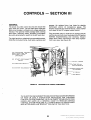
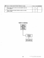
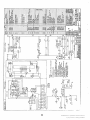
CONTROLS
- SECTION 111
GENERAL
gauges. An optional door has holes for electric
tachometer and/or oil temperature gauge. The
bracket supports the terminal blocks, cycle cranker
and relays in the DC engine control circuit.
The shock mounted control box has two doors that
open from the center. The left hand door holds the
field circuit breaker, voltmeter and voltage adjusting
rheostat. The optional meter package adds running
time meter, frequency meter, ammeter or ammeters
plus volts-amps selector switch to the left hand door.
Plug mounted relays in both the AC section and DC
section plus printed circuit modules in the DCsection
facilitate troubleshooting and servicing. Snap-in
lamps with Faston connectors make lamp replacement very easy. See Figure 28.
The right hand door, attached to a removable bracket,
holds the instrument lamp, fault lights, switches and
I
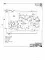
A12 C R A N K I N G LIMITER
(MAY A L S O U S E A N
O P T I O N A L CYCLE
CRANKER)
K11 S T A R T D I S C O N N E C
RELAY
-FAULT
K12 IGNITION RELA
LAMPS
TIME D E L A Y
K13 S T A R T S O L E N O I
-ENGINE
MONITOR
PC B O A R D
\KI
l
FIGURE 28.
LOCATION OF
RELAY
K
2 RELAY
DC CONTROL COMPONENTS
THE QUESTION AND ANSWER TROUBLESHOOTING GUIDES BEGINNING
ON PAGE 39 GIVE A STEP-BY-STEP PROCEDURE FOR CHECKING
CONTROL SYSTEM PROBLEMS. THEFLOW-CHART TROUBLESHOOTING
GUIDES ARE GIVEN AS A GENERAL GUIDE TO RESOLVE VARIOUS
CONTROL SYSTEM PROBLEMS. ALL CHARTS REFER TO PROCEDURES
AND NOTES WHICH ARE GIVEN AT THE END OF THIS SECTION.
39
Redistribution or publication of this document,
by any means, is strictly prohibited.
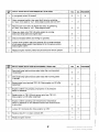
QUESTION AND ANSWER TROUBLESHOOTING GUIDE
FOR UNITS WITH ONE FAULT LAMP
To correct a particular problem, answer the question either “yes“ or “no” then proceed to the next step given in
whichever column question was answered.
TABLE A. ENGINE FAILS TO CRANK WHEN SWITCH TO “RUN”
Does fault lamp light?
1.
2.
~
1
Is battery connected correctly and is voltage normal?
~~~
~
l 3
I
I
relay K13’ (start solenoid) pick up?
3.
4.
YES
Does ignition relay K12 pick up?
I
l7
lo
Is voltage from ground terminal to center terminal of
run-stop-remote switch equal to battery voltage?
7
6.
Switch is defective or in “stop” position.
-
7.
Is voltage from ground terminal to ignition relay K12 terminal
“B” equal to battery voltage?
5.
0.
9.
10.
I
lo
Jumper battery positive from center terminal of run-stop-remote
switch to terminal “6”of ignition relay K12. Does engine
now crank?
9
Replace engine monitor printed circuit board.
-
Is voltage from ground to terminal 26 on
battery voltage?
,
TBll equal to
14
11.
Does ignition relay K12 (4-7)contact close?
12.
a. Check socket connection.
b. Coil may be open.
c. Replace ignition relay K12.
13.
Clean relay contacts and check wiring.
13
I I
14.
15.
Is voltage from ground to start disconnect relay
equal to battery voltage?
K11 terminal 1
Clean relay contact K11 (7-1)and check wiring.
I
l6
I -
NOTE: On EK. EM, and EN series, start solenoid relay is mounted on the engine,
rather than in the control, and is designated K6.
40
Redistribution or publication of this document,
by any means, is strictly prohibited.
t
ITEM
NO.
A. ENGINE FAILS TO CRANK WHEN SWITCHED TO “RUN”
(Continued)
YES
NO
Is voltage from ground to coil terminal of K13’ start solenoid
I equal to battery voltage?
17
18
17.
Does voltage from ground to TBll-22equal battery voltage?
21
20
18.
Jumper from K13’ coil terminal to
Does relay K13’ pick up?
19
-
16.
K11 terminal 1.
19.
Replace cycle cranker printed circuit board A12.
-
-
20.
Replace start solenoid K13’.
-
-
21.
Is voltage from ground to starter coil terminal equal to
battery voltage?
22
23
22.
Replace starter.
-
-
23.
Check thermal breaker CB1 and wiring to starter.
-
-
PROCEDURE
‘NOTE: On EK. EM, and EN series. start solenoid is mounted on engine,
rather than in the control, and is designated K6.
TABLE A. SYNOPSIS
ENGINE
FAILS TO
CRANK
A12 CYCLE
CRANKER
FAILS
LOOSE OR
REVERSED
BATTERY
CONNECTlO N
IGNITION
RELAY K12
FAILS
I
K12 COIL
(4-7) FAILS
TO CLOSE
41
START
SOLENOID
FAILS
MONIT0R
PRINTED
CIRCUIT BOARD
~
SOLENOID
COIL OPEN
SOLENOID
CONTACT FAILS
TO CLOSE
CONTACT FAILS
TO CLOSE
CIRCUIT PATH
Redistribution or publication of this document,
by any means, is strictly prohibited.
ITEM
NO.
TABLE B. ENGINE SHUTS DOWN IMMEDIATELY AFTER START
YES
1 Is overspeed switch S3 closed?
1.
1
NO
PROCEDURE
NO
IPROCEDUREI
2
Open overspeed switch, then reset fault lamp by switching
to “stop”, then back to “run”. Does engine crank and run OK?
I
Remove wire from TB11-29. Reset fault lamp by switching
to “stop”, then back to “run”. Does engine crank?
4
Place wire back onto TB11-29 while engine is running.
Does fault lamp light and engine stop?
5
5.
Check overspeed switch and wiring for grounds.
-
6.
Jumper from ignition relay K12 terminal “B” to center terminal
of run-stop-remote switch. See Method M in Procedure section.
Does engine crank?
7
Replace engine monitor printed circuit board and remove jumper.
-
~
7.
I
ITEMTABLE C. ENGINE SHUTS DOWN AFTER RUNNING A SHORT TIME
NO.
YES
I
I
1.
Does fault lamp light and does plant stop after running about
12 seconds?
2.
Does fault lamp light and does plant stop after running about
1 minute?
3.
Remove wire from terminal TB11-30. Does engine run
restarting?
4.
Engine is either not pumping oil properly or oil pressure
sensor is defective.
~
. 5.
6.
7.
OK after
Replace wire on TB11-30 and remove wire from TB11-31.
Does engine run OK after restarting?
6
Engine is either operating over temperature, temperature
sensor is defective or wire between sensor and terminal block
is grounded.
-
Jumper K11 terminals 6-9. Does engine run OK?
a
~~
~
8r-1 Replace r e l a y G 1 or clean contacts 6-9.
9.
I
Replace engine monitor.
42
Redistribution or publication of this document,
by any means, is strictly prohibited.
ITEMTABLE
NO.
D. ENGINE HESITATES WHEN ATTEMPTING TO CRANK
YES
1.
Does engine crank as soon as run-stop switch is put into
“run” position?
2.
Check contacts K12 (3-9)for failure to close or to make
proper contact.
NO
PROCEDURE
TABLE D. SYNOPSIS
ENGINE
SOMETIMES
HESITATES
BEFORE
CRANKING
5
I
43
DIRTY CONTACTS,
BAD CONNECTION
I
Redistribution or publication of this document,
by any means, is strictly prohibited.
.
ITEM
NO.
TABLE E. STARTER FAILS TO DISENGAGE OR TRIES TO RE-ENGAGE WHILE
RUNNING
I
YES
1.
Does starter continue to run after engine starts?
2
2.
Does charge ammeter show a charging current while running?
4
3.
Is charging alternator belt on and driving alternator properly?
4.
Does start disconnect relay K11 and starter protection relay
K14 pick up when engine starts?
5.
Does voltage from ground to K13’ coil terminal drop to zero
when K11 relay picks up?
6.
Does voltage at starter terminal drop to zero when K13* drops out?
7
7.
Check for faulty starter.
-
8.
Start solenoid contacts may be welded - replace K13’ solenoid.
.
~
9.
10.
.
I
~
Check K11 and K14 contacts (1-7) to make sure they open when
relay picks up.
l 4
l6
I -
l-
Does voltage across K11 terminals (A-B) build up’to battery
voltage?
11.
Replace start disconnect relay K11 or starter protection
relay K14. Coil may be open.
12.
Does relay K12 (5-8) close to bring battery voltage to
alternator regulator?
11
l-
I
l3
13.
Check for faulty alternator, regulator or shorted
alternator output.
-
14.
Check K12 ignition relay for dirty contact or broken wire.
-
,
NOTE On EK. EM and EN series, start solenoid is mounted on the engine,
rather than the control, and is designated K6.
44
Redistribution or publication of this document,
by any means, is strictly prohibited.
TABLE E. SYNOPSIS
J
STARTER
FAILS TO
DISENGAGE
START SOLENOID
COWTACT FAILS
TO OQEN
-
ENERGIZE
START DISCONNECT RELAY
K11 AND K14
D.RlVE BELT
OFF OR
SLIPPING
7
I
K14 STARTER
PROTECTION
RELAY FAILS
-
START
DISCONNECT
RELAY K11
FAILS
AND-c
IGNITION RELAY
K12 (5-8) FAILS
TO CLOSE
w
7
1
I
K14 COIL,
.
'
K11 START
DISCONNECT
COIL OPEN
I
I
I
,
CONTACTS 1-7
ON K11 FAIL
TO OPEN
CONTACTS
1-7 ON K14
FAIL TO OPEN
ALTERNATOR
OUTPUT SHORT
CIRCUITED
DEFECTIVE
REGULATOR
/G\
NOTE: Whenever a letter appears near the box, a separate procedure, corresponding to
that letter, is given at the end of this section.
-
K14 starter protection relay was added to units beginning with the Specs shown below.
This relay prevents starter engagement when unit is running.
SERIES
SPEC
SERIES
SPEC
SERIES
SPEC
SERIES
SPEC
EK-EM
EN
KB-KR
DDA-MDDA
DDB .
D
A
P
A
A
DEH
DEF
DEG
DFE
DYA
D
F
D
H
C
DYC
DYD
DYG
(150-175 kW)
DYJ
B
A
WA
WE
WB
F
B
H
45
A
A
Redistribution or publication of this document,
by any means, is strictly prohibited.
QUESTION AND ANSWER TROUBLESHOOTING GUIDE
FOR UNITS WITH 5 FAULT LAMPS
-
I L‘ kM I
-
TABLE F. ENGINE FAILS TO CRANK
When switch is put into “run” position, does. engine csank? . :
’
.
.
’
Is battery connected correctly and is voltage normal?
-
YES
NO
-
2
3
-
PROCEDURE
I
.
Does one of the following fault lamps light?
(Choose one of the following:)
I
I
’
30
25
27
29
..
Overspeed?
High Engine Temperature?
Low Oil Pressure?
Overcrank?
-
. .
I
Does ‘relay K13* (sfarfsolenoid) pick up?
22
5
Does ignition relay K12 pick up?
11
6
Is voltage from ground terminal to center terminal of run-stopremote switch equal to battery voltage?
8
7
Switch is in “stop” position or defective.
-
-
Is voltage from ground terminal to ignition relay K12
terminal “B” equal to battery voltage?
1131g1
I
Jumper battery positive from center terminal of run-stop-remote
switch to terminal “B” of relay K12. Does engine crank?
~~
I
I 1 0
1-1
1
. M
~~
Remove jumper and replace engine monitor printed circuit board.
-
-
Is voltage from ground to terminal 26 on TB11 equal to battery
voltage?
15
12
Does contact ignition relay K12 (4-7) close?
14
13
Clean socket connection. Coil may be open. Replace ignition
relay K12.
-
-
Clean relay contacts or replace relay and check wiring.
-
-
NOTE: On EK. EM and EN series, start solenoid relay is mounted on the engine,
rather than in the control, and is designated K5.
46
Redistribution or publication of this document,
by any means, is strictly prohibited.
15.
Is voltage from ground to K11 iterminal 1 equal to
battery voltage?
16.
Clean relay contact K11 (1-7) and check wiring. Replace
relay K11 if necessary.
17.
Does voltage from ground to coil terminal of K13’ start
solenoid equal battery voltage?
18.
Does voltage from ground to TB11-22 equal battery voltage?
19.
Jumper from K13* coil terminal to K11 terminal 1.
Does relay K13* start solenoid pick up?
I
17
I I
18
I I
l6
l9
22
20
I
20.
Replace cycle cranker and check printed circuit connection.
21.
Replace K13* start solenoid.
22.
Does voltage from ground to starter coil terminal equal battery voltage?
23
24
23.
Replace starter.
-
-
24.
Check wiring between TB11 terminal 22 and starter. Some units
have an automatic resetting circuit breaker in this circuit.
25.
Remove lead from TB11-31. Reset by switching to “stop”,
then back to “run”. Does engine crank OK?
26
29
26.
Inspect for bare wires and shorts to ground. Replace engine
temperature sensor.
-
-
27.
Are relay contacts K11 (8-5) open?
29
28
28.
Replace relay and reset by switching to “stop”, then back to
“run”. Does engine crank OK?
-
29
29.
Replace engine monitor printed circuit board.
-
-
30.
Remove lead from TB11-29. Reset by switching to “stop”, then.
back to “run”. Does engine crank when switched to run?
31.
Replace the lead to TB11-29 when engine is running. Does
overspeed lamp light and engine stop?
1 - 1 - 1
1-1-1
I I I
I I I
29
31
’
I
32
I
33
I
I-1-1
32.
Check for defective overspeed switch or bare wires grounding
terminal TB11-29.
33.
Stop and start engine several times. Works OK?
-
34
34.
Replace engine monitor printed circuit board.
-
-
I
I
NOTE: On EK, EM and EN series, start solenoid is mounted o n the’engine,
rather than the control, and is designated K6.
Redistribution or publication of this document,
by any means, is strictly prohibited.
ITEM
NO.
1.
2.
3.
’
YES
TABLE G. ENGINE SHUTS DOWN AFTER RUNNING A SHORT TIME
~
~
~~~
Does low oil pressure lamp light and plant stop after running
about 12 seconds?
3
Does overcrank lamp light and plant stop after running about
1 minute?
5
Remove wire from terminal TB11-30. Reset alarm by switching
to “stop”, then back to “run”. Does engine run OK?
(Replace wire after test.)
l-
Engine is either not pumping oil properly o r oil pressure
sensor is defective.
5.
Does relay K11 pick up after engine starts?
6
6.
Jumper relay K11 contacts (6-9) after engine starts.
Does engine continue to run OK?
(Remove jumper after test.)
7
7.
Replace relay K l l .
-
8.
Replace engine monitor printed circuit board.
-
9.
Does charge ammeter show a charging current while running?
10
Does battery voltage appear across K11 co,iI terminal (A-B)
when engine runs?
7
11.
Check for an open circuit in wiring or a loose connection
from alternator “AUX” terminal to K11 coil circuit.
12.
Check .alternator and regulator output; replace if necessary.
PROCEDURE
,
4
4.
10.
NO
~
l-
-
TABLE G. SYNOPSIS
SHUTS DOWN
I
I
I
TEMPERATURE
START DISCONNECT RELAY
K11 (6-9)
1
AEE:YF:E
SENSOR CLOSED
PRESSURE
1
SENSOR CLOSED
F ’ % w
I
NO ALTERNATOR
OUTPUT
I
I
I
SWITCH
. ovER:EED,CLOSED
I
A-11 ENGINE
MONITOR
PRINTED CIRCUIT
DEFECTIVE
REGULATOR
48
Redistribution or publication of this document,
by any means, is strictly prohibited.
I
SINGLE LAMP
ENGINE MONITOR
FAULT
FAULT
ENGINE
FAILS TO
CRANK
LOW OIL
PRESSURE
OR HIGH
ENG. TEMP.
CIRCUIT
FAILS AFTER
APPROX. 12
SECONDS *'*
PATH 9-7
ON A-11
PRINTED
CIRCUIT
BOARD
K1 RELAY
CONTACT
FAILS TO
CLOSE
LIGHTS AS
SOON AS
RUN SWITCH
CLOSED
LIGHTS AND
ENGINE
SHUTS DOWN
DIODE
CR3
OPEN
TRANSISTOR
0 7 FAILED,
SHORT
EMITTER TO
COLLECTOR **
.
CAPACITOR
c2
SHORTED
NOTE: Whenever a letter appears near the box, a separate procedure, corresponding to that
letter, is given at the end of this section
**
I..
-
With swiich in run position, check for voltage across R9 (27-ohms). A voltage of 0.5 to 1.0
will turn on SCR CR6. If voltage is present, remove TB11 terminal 29. If voltage is still
present, check transistors 0 7 for short-emitter to collector.
Remove TB11 terminal 30 and 31. If engine still shuts down, remove transistor Q8. If this
prevents shutdown - replace Q8.
SCR CR6
SHORTED
r
EXTERNAL
ALARM
FAILS ON
ALARM
SHUTDOWN
CONTACT
FAILS TO
CLOSE ON
SHUTDOWN
CIRCUIT
PATH 9-8
OPEN
ENGINE
MONITOR **
I
ENGINE
FAILS TO
CRANK
LIGHTS AS
SOON AS RUN
I
CIRCUIT PATH
18-19
OPEN
HIGH ENGINE
TEMPERATURE
LAMP LIGHTS
I
I
LOW OIL
PRESSURE
LAMP LIGHTS
ENGINE
SHUTS DOWN
I
I
OVERSPEED
LAMP
LIGHTS
-
OVERCRA'NK
LAMP
LIGHTS
_
I
LAMP LIGHTS
AFTER APPROX.
12 SECONDS
-
TRANSISTOR
Q6 FAILS TO
TURN OFF
K1 RELAY
CONTACT ON
A-11 FAILS TO
CAPACITOR
C6
OPEN
TRANSISTOR
Q10
SHORTED
T
I
CAPACITOR
F
l
CAPACITOR
POTENTIOMETER
R-15 ON A-11
PRINTED ClRCUl
BOARD FOR
CORRECT TIME
CAPACITOR
CAPACITOR
OPEN
OPEN
I
I
TRANSISTOR
Q13
SHORTED
POTENTIOMETER
R2 ON A-11
PRINTED CIRCUIT
BOARD FOR
CORRECT TIME
T
I
CAPACITOR
.
NOTE: Whenever a letter appears near the box, a separate procedure, correspondjng to that
letter, is given at the end of this section.
'
**
-
Capacitor C1 must be discharged when engine starts to prevent an overcrank shuidown.
Check relay contact that connects to terminal 16 of engine monitor.
See typical wiring diagram.
'
..
.-
I-
.
OVERCRANK
RELAY FAILS
TO DISCHARGE
CAPACITOR C1
ADJUSTMENTS AND P.ROCEDURES
If starter fails to disengage, the engine may
drive starter to unsafe speeds that could
cause starter rotor windings to separate.
Inspect contacts for dirt particles, obstructions or
insulating film. Clean, using low pressure compressed air and bond paper. Check relay socket.
Contacts are normally closed when engine is not
running. Contacts must open when engine is running
normal.
R E M O V E K11 OR K 1 2 F R O M
C O N T R O L B O X (PULL S T R A I G H T
up). cT)NNECT A N O H M M E T E R
TO TERMINALS M A R K E D "A"
A N D "6" O N B A S E O F R E L A Y .
IH1
O F 12 V O L T RE.LAY
IS 120 O H M S . R E S I S T A N C E O F
2 4 V O L T R E L A Y IS 4 7 0 O H M S .
Contacts are normally open; contacts close for alarm
condition only. (Overspeed switch may have to be
reset manually.)
IJI
Contacts may have welded closed or plunger may be
stuck. Remove solenoid from circuit to test for proper
operation.
FIGURE 29. TESTING K11 AND K12 RELAYS
[KI
Inspect printed circuit board paths that supply
voltage to relay K12. (Between terminals 18-19of 3000681; between terminals 7-9 of 300-0679.)
When connecting battery cables, terminal will spark i f
connection is reversed.
Unit will not crank with reversed cables or loose
connections.
DC alternator will overheat and will probably burn up.
[LI
A reverse battery connection will show a maximum
positive charge on the DC ammeter.
Remove cycle cranker printed circuit board and
jumper terminal 2-3 to by-pass cycle cranker circuit.
On dry charged batteries, no woltage is present until electrolyte is
added.
See ooerator's manual for alternator belt tension
edjustment.
In an extreme emergency, engine may be operated
without any safeties by removing engine monitor
printed circuit board and jumping terminals 7-9. (It
may be easier to jump from center contact of RunStop switch to terminal "B" on Kl-2 relay; see Figure
30.)
Check for voltage from starter terminals to ground.
Voltage should be present at both terminals when
solenoid is energized for cranking.
51
Redistribution or publication of this document,
by any means, is strictly prohibited.
'
Units With Five Fault Lamps: Potentiometer H2 on All printed circuit board is factory adjusted for 75
seconds ( ' 5 seconds). To lengthen delay, use a
screwdriver and turn R2 clockwise; to shorten delay,
turn counterclockwise. See Figure 32.
R15 OIL PRESSURE
D E L A Y - FACTORY SET
A T 12% SECONDS
SWITCH
\
. . '.
FIGURE 30. EMERGENCY STARTING
R 2 OVERCRANK DELAY'
-FACTORY SET A T
75 SECONDS
ADJUSTING LOW OIL PRESSURE TIME
DELAY ON ENGINE MONITOR PRINTED
CIRCUIT BOARD
FIGURE 32. ADJUSTING TIME DELAYS ON'FIVE
LAMP ENGINE MONITOR
Units With Single Fault Lamp: Potentiometer R l O on
A-11 printed circuit board is factory adjusted for 12112 seconds ( ? 2-1/2 seconds). To lengthen delay,
use a screwdriver and turn potentiometer clockwise.
To shorten delay, turn ' potentiometer counterclockwise. Refer to Figure 31.
ADJUSTING OPTIONAL CYCLE CRANKER
The optional cycle cranker is factory set:for 15
seconds crank time and, 10 seconds rest time. To
lengthen crank time, .turn potentiometer R4
clockwise; to shorten crank time, turn counterclockwise. To lengthen rest time, turn potentiometer R1 clockwise; to' shorten, turn counterclockwise. See Figure 33.
Units With Five Fault Lamps: Potentiometer R15 on All printed circuit board is factory adjusted for 12-1/2
seconds ( 2 2-1/2 seconds). To lengthen delay, use a
screwdriver and turn clockwise; to shorten delay, turn
counterclockwise. See Figure 32.
1
4
A12 C Y C L E CRANKEF
ADJUSTING OVERCRANK TIME DELAY
ON ENGINE MONITOR PRINTED CIRCUIT
BOARD
3OOC714-12V.
3OOC715-24V.
'
'
Units With SingleFault Lamp: Potentiometer R4on All printed circuit board is factory adjusted for 75
seconds ( r 5 seconds). To increase delay, use a
screwdriver and turn R4 clockwise; to shorten delay,
turn counterclockwise. See Figure 31.
R 4 OVERCRANK D E L A Y
(FACTORY SET A T
R 4 C R A N K TIME
FACTORY SET A T
15 SECONDS.,
T O INCREASE
T U R N CLOCKWISE
OIL PRESSURE DELAY
(FACTORY SET A T
12% SECONDS)
\
R1 R E S T TIMEFACTORY SET A T
10 SECONDS.
TO INCREASE
TURN CLOCKWISE
FIGURE 31. ADJUSTING TIME DELAYS ON SINGLE
LAYP ENGINE MONITOR
0
FIGURE 33. OPTIONAL CYCLE CRANKER
ADWSTMENTS
52
Redistribution or publication of this document,
by any means, is strictly prohibited.
WIRING DIAGRAMS
612-4173
612-3919
625-1007
625-0987
612-4350
612-4353
300-0679
300-0680
300-0681
300-0682
300-0714
625-1036
612-5300
612-5301
612-5302
612-5303
612-5304
612-5305
612-5310
612-5311
612-5312
612-5313
PAGE
100-175 kW Brushless Exciter ......................................
-54
30-90 kW Static Exciter ............................................ -55
VR21 Brushless Exciter ............................................. 56
VR21 Static Exciter .................................................
57
30-50 kW Controls .Single Light ....................................
58
30-90 kW Controls .Five Light ......................................
59
Engine Control Monitor .12 V .......................................
60
Engine Control Monitor .24 V .......................................
61
Engine Control Monitor 12 V Five Light ............................
62
Engine Control Monitor .24 V . Five Light ............................ 63
Cycle Cranker .12 V ............................................... 64
Tap Switch ......................................................... 65
25-90 kW Brushless 15R; 515R .....................................
166
25-180 kW Brushless, Full Meter Panel ...............................
67
25-45 kW-3R Brushless 120/240 V . 1 Phase ..........................
68
25-45 kW .3R Brushless 120/240 V . 1 Phase, Full Meter Panel . . . . . . . .69
25-90 kW 9XR Brushless 347/600V ...................................
70
25-180 kW .9XR Brushless 347/600V. Full Meter Panel ...............71
Generator Set Engine Control, 12V Ignition; EK, EM, EN .............. 72
Generator Set Engine Control, 12 V Ignition; EK, EM, EN ............. 73
Generator Set Engine Control, 12V ignition; KR, WA .................74
Generator Set Engine Control, 12 V Ignition; KR, WA .................75
.
.
53
Redistribution or publication of this document,
by any means, is strictly prohibited.
1
I
612C4173
I
WIRING MAGRAM
CONTROL BOX (INSIDE)
111.
TI T 2
FIELO
1
W 12- NOTE
SEE VOLTAGE
CHART
I
M23
M?4
v
HOUSING-CONTROL BOX
T2
n.
v
... ..
IC ,a<,
.--._
I
SCHEMATIC DIAGRAM
__ -
REAR VIEW_-P/\NEL
s
I
I
cfs
C821
7
rT6
CT21-23
.TI2
$7
1
3208431
ow
I
320P307
I
LOCKXKTBRKR HANDLE [PENNSTATE
3028743
,3028744
'3088745
3028746
3028747
3028748
I
TRANSFORMER ASSY-CUR t 2 5 - 4 0 K W
TRWSFORMER ASSY-CUR(41-45KWl
FIANSFORMER AS=- CUR ( 4 6 6 o ( w I TRANSFORMER ASST- CUR (61-lWl(W
TRANSFORMER *SSY~CUR(IOI~IUI:Wl
TRANSFORMER A3SY-CURU26-175KWI
PA111
M
rnY.!"O*
CIRCUIT BREAKER. 2hMP
I
I
I
I
I
a
d
-
T3 7
ELlt3219
3150322
I
VR21
33201268 1
VR22 305D49NREa
WII
3380525 1
W12
336A1913 I
I---
-
NOTE:
CONNECT LEAO W12 FROM
TERMINAL TB21-63 TO 7821-IH-I
PER VOLTAGE CHART BELOW
--
I
ROARDASSY-PC V0LTA:E RGLTR
CHASSIS ASSY-VOLTAGE RGLTR
WIRING HARNESS
LEAO ASSY
,
VOLTAGE CONNECTIONS
.. .
115/23OV, 50Hz,(H61
120/240V, 60H2, (H51
1
I
I
I
, -.
-.
I15/2WV, 50 Hz. (H41
IZOl2JEV. 60Hz,(H31
127/220V, 60 Hz,(H41
I39/240V. . 60 HZ.(H51
.
-.. -.
,-234/40OV, 50 Hz. (H41
240/416V, 60 Hz,(H3)
254/440V, 60 Hz.( H4)
277/480V. . 60 Hz..(H51
I'PHASE
115/23OV, 5 0 H z . (H61
120/240V, 60Hz. (H5)
NOTE.
UNLESS OTHERWISE NOTED,
3PH.
50/60Hz
12
W RECONNECTABLE
-
. ........- -.--,.-- ,
612C4173
.
SCHEMATIC DIAGRAM
m111 ,'SI
,
CONTROL BOX (INSIDE)
nr.KS.
m.
32082
320818
yOPm7
CBZI
I'
6 :
-- T.-
-TI1
*TI2
I
I
-
G2A131
'
-
$
WI2-NOTE
SEEVOLTAGE
CHART
%
TI
T2
T3
74
TS
T6
77
\
i
I
T
2
%
-
.
.
K L . x)781061
- 30lK.224
I
I --
_ -HOUSING-CONTROL BOX
TO
T9
*
\
I
\
\
\
0
I
I
\
3
\
Si!
-I
-I
NOTE.
CONNECT LEAD W12 FROM
TERMINAL TB21-63 TO'TEZI.IH,)
PER
CHART
VOLTAGE CONNECTIONS
3 PHASE 1I
-
GENEfiIATOR
110/190V.
115/2WV,
120/208V,
127/220V,
139/240V,
115/23OV. 50H1, (H6)
120/240V, 60Hr, (H51
220/3EOV, SO HI. (til)
234/400V, 50 HI, (H4)
2 4 0 / 4 1 6 V 60 Hr:(H4)
HZ (H3)
254/440$60
5CJHr, (H3)
50 Ht. (H4)
60 HZ.lH3)
60 Hr,(H41
60 Hr.(H51
277/480V, 60 HZ. (ti51
T7
F2
I
LI
FIELD
LO
(MOUNTED
IN E N )
6 7 8 910
O O Q Q ?
5
4 1
TI I
I
-
L3
NOTE.
UNLESS OTHERWISENOTED,
ALL COMPONENTS ARE SHOWN
IN THE 0E.ENERGIZED
POSITION
DS22 '
LO
.
KxmnM
aiv
CIRCIJI_T BREAKER.IIAW IZS-WKN
I CIRCUIT BREAKER. 2 0 W P ( 4 - 9 0 K W l
I J O B C K T ERKR HANDLE (PEW STATE
I
I
I
I
'
'
I
--a
LIGHT-UPPER SCALE
LIGHT-LOWER
7GENEFA! I TRELAY-VOLTAGE
11
---q
SELECTOR
.BRACKET- RELAY MTG
_.
-
625D1007]
; I
!
VRZl
WARD A5SI- PC
332DIL68
i
I
Lr
-
. ,\..,.
r
1
.. . . . . . .
I
... .
pi
i
----T8
. I. ..
CII
I
4 l - ..
c121.47 T
R27
100 K
*--
i
I N
N
5
B
I-
.;
57
Redistribution or publication of this document,
by any means, is strictly prohibited.
-
I
I ?
1.:
12
I
I
D
---i
_-
7
I
. ..
I
. I
N
*
i
i
58
Redistribution or publication of this document,
by any means, is strictly prohibited.
.
612C4353 1
-WIRING
- DIAGRAM
(FRONT VIEW1
I
Z V 8OMA
c ;EMOTE
hNNUNCIATOR
IUEBCRANK
.ow oh PRES!
I1 EN6 TEMP
I
-7
--
SCHEMATIC DIAGRAM
(REAR V I F Y I
I6
,1
1)
i
9
10
.C CNG TEMP
I
id
iENERATlNG
I
s2
53
I
NOTES:
I. W12 USED ON STD CONTROL ONLY
2.USED ON PRE-ALARM CONTROL ONLY
3.REMOTE ALARM CIRCUIT RATED 5AMP
MAX
4.SHUTDOWN 8 A L A R M S
4.1 STD CONTROL
4.1.1 SAFETY SHUTDOWN 8 ALARMS Oh
OVERCRANK,OVERSPEED,HI ENG TEMP
8 L O OIL PRESS
4.1.2 SAFETY A L A R M ONLY ON LO ENG
TEMP
4.2 PENN STATE CONTROL
"
"
I 6 3 ON TBZl
4.2.1 SAFETY SHUTDOWN a ALARMS
30-24OVAC
ON OVERCRANK 8 OVERSPEED
vi
4.2.2 SAFETY A L A R M S ON HI ENG
T E M ~ L OOIL PRESS a LO ENG TEMP
4.3 PRE-ALARM CONTROL
4.3.1 SAFETY'PRE-ALARMS ON HI EN(
TEMP 8 LO OIL PRESS
4.3.2 SAFETY SHUTDOWN a ALARMS
ON OVERCRANK,OVERSPEED,HI ENG
TEMP e LO OIL PRESS
KI I
4.3.3 SAFETY ALARM ONLY ON La EN(
13
TEMP
B U A
WHEN U S E D
5.S3 OVERSPEEO SWITCH MOUNTED IN
GENERATOR END B E L L
ISTP
&UNLESS OTHERWISE NOTED,ALL
CRANKER CR*NKI
COMPONENTS ARE SHOWN I N T H E
ST^ C ~ N T R O L
-01
-03
-01
,-04
DE-ENERGIZED POSITION
.ICRE+iLARMBPENH
$TATELSWE&QF)
...... "..
,
n
ICYCLE
F?'ps 4
1931108
1931109
193A104
SI
.
IHlADDCD DDA.DDB,DYJ
El
P E N N STATE (SPEC:C,D,E.ECI
-0s
-06
s5
S6
57
1
I I I SWIICH-LOW Dl1 PRESSURE
1 I 1 SIlTCH-HIGH WATER TEMP
I
I
StNOER -011 PRESSURE
SEWOER-WATER TEMP < O V A . O K )
SINOER-WATER TEMP. (OEF. OEH.
FUEL PUMP
I
I
I
C I R C U I I B R E I K t R . I 7 5 AIP(0VC OHLVJ ,
I
I
I
I
_. -
I
' I
I
I TO TERM 62
I 8 63 ON TB21
I 190-24OVAC
1201%3-
12
II
IVERSPEED
CBI
-
I
1 f SIITCH-OYIRSPfEO
I
I
- 4;
I
I
OEC)
I
S?ITCH-LOI l I T f R TEMP
SWITCH-LOU 011 PRESS (PRE.lJARI)
'
SIITCH-HIGH WATER TEMP (PM-ALARM)
300C679
I
I
.
HOW:
1. SOLDER fER SOLDERIH6 PROCESS MIL-S-1872
ITEM 23.
U S I N S SOLDER.
2 . SOLDER J O l H l S AN0 OR C W O N E N T LEAOS SHALL NO1 PWOJECT
MORE THAN 3 4 6 BLYOND SURFACE OF BOARD.
@
Q)
0
FUELSOL >R
IGN RLLl
7
17-
9
I
t
X5
--1
3. F A C l O R l AOJUST POTEHTIOYETER R13 FOR 12.5 f 2 . 5 SECONDS LOP 01111.
FACTORY AOJUST POTENTIDPETER R4 FBR 7 5 2 IO SECONDS O V E R C R d K 01111.
A9
19
RE
I8
I7
.RtO
A6
A2
P I I1
16
15
14
I3
350-517
550-505
I
RESISTOR
I
RESISTOR
350-572
3031169
350-552
350-526
I
2
1
350-536
2
RESISTOR
POTENTIOIETER
RESISTOR
RESlSlOR
RESIPIOP.
I
27n
2.711
I iim
3.5 YEm
22m
15On
loom
7 8 9 IO I I I2 I3
1
1
1
1
I4
1
1
1
'
1
1
1
1
NOTES'
I . SOLOEk ?ER SOLOLklNf PROCESS MIL-S-6172 USINC SOLOER.
ITEN 23
2 SOLOER JOINIS ANU'OR'COYPONEkT LEAOS SWLLL HOT PHOJECI
MORE IHAN 3 16 3tlWO SURfACL OF EOARO.
D
3. SET R4
4.
FUEL SQL OR
IGN RELAY 7
8
I-~-n
n
FOR AN OVERCRANK TIME OELAV
Of 1525 SEMNOS
ton OIL PRESS TIME OELAY SHOULD BE i z . 5 i z . 5 SECOHDS
71
I
P
62
Redistribution or publication of this document,
by any means, is strictly prohibited.
i
I
I
"
c
63
Redistribution or publication of this document,
by any means, is strictly prohibited.
...
d
BY
AVl3U N9I
CB M I N I I
:
I
'.\
.
-_
I
@
- - - .
e
- - -
EQUIVALENT CIRCUIT
-1
h
I
A
\-
I
I
I
L3
120/208V, 3 @
L3
120/240 V, I #
I
I
NOlcS:
I. REMOX JiiMFER W12 B i X E E N TB21-i3 & Ta21-H3.
MOUNT VOLTllGC SELECTOR RELAY X!!j I N UOKTROL
BOX AND l l R E A; SHOWN. RELAY WILL ENEOGIZ:
Oi4 120 '29BV 30 CIRCUIT COMPLETING CONNECTION
BETWEEN TB21-63 I TB21-H3.
RELAY WILL RElAAlN
DE-ENERGIZED ON 1 2 0 / 2 4 0 , 1 1 CIRCUIT COMPLETING
CONNECTION BETWEEN TB21-63 & TB21-H5.
WRING DIAGRAM
--
/0
/?
CEkTROL BOX (INSIDE)
SCHEMATIC DIAGRAM
.
11115 L'51
'
G21
7
I
I
;if.
T5
DES
CB21
1
1
,
m r NO
3208431
law
I
I
MXfiIIItON
I IClRCUlT BREAKER.2AMP
GENERATgR
RELAY-VOLTAGE
---
I_
__
_
-HOUSING-CONTROL BOX
t
~ 2 1
ADJ 3 5 ~ 3 5 ~
303P32
I I IKNOB-RHEOSTAT
1350-5561REfll I I RESISTOR.47,ODO. IIPWATT
I
R22
I
I
I
I
I
1
I
I
'
. ._
5 0 H.I 1H41
60 Hzi(H31
60 HI, IH41
60Hz. 1H51
230/400V.
-240/416V;
2 5 4 /440V,
27?/480V.
L3
L3
-
NnTF.
UNLESS OTHERWISE NOTED,
ALL COMPONENTS ARE SHOWN
IN THE DE.ENERGIZED
, POSITION
VOLTAGE RGLTR
,
-
50 Hz. 1H51
50 Hz.1H41
50Hz.IH31
5 0 HI. IH41
60HZ.IH31
60 H z . ~ H 4 ~
60 HZ.IH51
LO
T5
1 BOARDASSY-PC
VOLTAGE CONNECTIONS
PHASE
__
- 3.
127/220V,
120R08V.
110/190V.
115/2OOV.
1201208V.
127/220V,
139/240V.
110/220V SOHz IH6l
=115/230<
50Hz:IH6l
1% 120/240V, 6 0 H z . !H5l
SELEZR-
i 3 ~ 3 ~ 1 s zii - I i RHEOSTAT-VOLTAGE
33201956
NOTE
CONNECT LEAD W12 FROM
TERMINAL T821.63 TO TL12I.IH-I
PER VOLTAGE CHART BELOW
I
'
60 Hz
-01
I
PfNN 6& Ik
ps
545A22
1.
I%R% L%T -AC CONT HOW.
1110/220V
51% I I5123OV:
5 0 H z (H61
50 H:I IH61
15R120/240V. 60H1. 1H51
--
CONTROL BOX (INSIDE)
I
C
I
t
1 I'li
TOVRZl
'
I
HOUSING-CONTROL BOX
EXCITER
WI2-NOTE.
SEE VOLTAGE
CHART
z
GENERATOR
I 545A23
I
I,
I
I
I
!WRTS
I
LIST-AC CONT HDW
SCHEMATIC DIAGRAM
C O N T R O L BOX IINS-IEE
0
\
‘2 T
pk/3D1II1LIM.$GiE7K-.S.O-.OOYI
302-0466 P
VR21
WIZ
I
I 1
I
I
I
1
I
I
I
I
I
I
! I
I
I
i I
I
--
L2
:
TIME
1332-19SS( D I I
BOARD 4SSY-PC VOLTAGE RGLTR
I
I 1
I
1330-076S D
I WIRING HARNESS
(336-1913 A I I I L E A 0 ASSY
I
-- USING-CONTROL BOX
METER-RUNNING
{
ZOEG-Z19
LL O
GENERATOR
I
CR4
CRS
CR6
F::
VOLTAGE CONNECTION
1201240 V
ALTERNATOR.
FIELD
T2
T2
L2
.
NOTE:
UNLESS OTHERWISE NOTED,
ALL COMPONENTSARE SHOWN
IN THE DE-ENERGIZED
POSITION.
(WIRING DIAGRAM)
l20/24CV. IPH.
.-
612-5302
12-5303
I
REAR
WIRING DIAGRAM
VILE
---
PANEL
SCHEMATIC DIAGRAM
,
C O N T R O L BOX I I N S I D E I
A C CONTROL PARTS 1151
EXCITER
ARMATURE
1wF/
FI
2
~
=
FOR VR SYSTEM SCHEMATIC
SE
-24S(Dl
/
I
621
L21
I
T2
I
I
I
I
I lGENERATOR
I I REACTOR A S S 1 COMY
1
I
I
I
I EOES-119 :
CT22
1
TO
GENERATOR
I
VOLTAGE CONNECTION
1201240 V
l
I B1
\
CT22
l
1
I 1
1315-0384
-2J7g
TI
i
I
CfYRlPllON
CIRCUIT BREAKER,ZA
LOCK-CKT BRKR HANDLE(PENN STATE1
RECTIFIER BRIDGE
TRANSFORUER A S S I - C U R
I
I
I
I
I
M
z3
]
I
USING.CONIROLBOX
u
0
P
C
B
1
I
ALTERNATOR
FIELD
I
:,' an.
Ii
WI2
I -
PART NO.
CB21
320.0431
320-0307
CR21 105-0524
CT21.22 3 0 2 - 0 7 3 9
KEf. C f S .
D
.U
C T 2L2
2
I
I
I I
I
I
512-5304
I
WIRING DIAGRAM
REAR VIEW-YNEL
SCHEMATIC DIAGRAM
CONTROL BOX IINSIDEI
EXCITER
,,
FOR VR
SEE625-1245101
SYSTEM SCHEMATIC
621
O
f
CR21
303-00761 -
'
SWITCH-VOLTMETER
I
I
SELECTOR
KNOB
I
I
I
1
I
I
I
M22
v
I
I
HOUSING-CONTROL BOX
I
I
I
I
I
I
I
I
I
I .
:
I
I
I
I
I
I
I
I
I
I
GENERATOR
VOLTAGE CONNECTION
3 PHASE, 3 4 7 / 6 0 0 V
I
ALTERNATOR
FIELD
T3
67.1
9
TO
65
'I
I
NOTE:
UNLESS OTHERWISE NOTED,
A L L COMPONENTS A R E SHOWN
IN THE DE-ENERGIZED
POSITION.
I
I I
I
I
-
ItOES 2 19
I
I
612-5305
I
REAR_VI_EW PANEL
SCHEMATIC DIAGRAM
CONTROL BOX l!NSIDE)
fI
8
r-
WIRING DIAGRAM
I
'G21
I
K
T21
b
A
I
L21
M23
TO VR21
I
lG
M
--USING-CONTROL
EXClIER
F+
GENERATOR
I REACTOR ASSYCOMM
I
I
BOX
M22
-
3020779 P
I
. ~~LTMETER+C.O-75OV
I300V
MOVEMENT)
M23
302-0221 B
M24
3024466 P
I
I
METER-FkEOUENCVf240)
METER-RUNHINO TIME ( 2 4 0 V l
F
---
I
L3
^-
I
I
w12
n
EXCITER
......-..
I
1115-03841 81
I
I
1
nrr
I II
I
i
I
I
I
I I
I I
I
I t
I
I
VOLTAGE CONNECTION
3PHASE.S47/600V, 60Hr
ALTERNATOR
FIELO
65
l C T 2 3
5
KW
2535
36-55
56-70
71-110
60H
-01
PLNNW
L3
. .
NOTE:
-02
-03
-04
-07
-08
-09
-10
Ill -145
-05
-11
POSITION.
146-180
-06
-12
ALL COMPONENTS ARE SHOWN B ~ U S ~ L ~ S S
I N THE DE-ENERGIZE0
347/ECOV,
4W.,60 HZ 3 P H ,
(WIRING DIAGRAM)
OWL
612-5305
1
I
I
!
j
I
0
2 2
72
.
N
Redistribution or publication of this document,
by any means, is strictly prohibited.
S S 3 M d 110 0 1 9 d W 3 1
OR3 l H ' O 3 3 d S Y 3 A O ' n N V Y 3 Y 3 A O NO
S W Y V l V B AMOOlllHS ,413315 Z'E'b
I
03511 N ~ I M
.
S S 3 Y d 110 01 9 d W 3 1
N 3 I H N O S W Y V l V - 3 Y d A 1 3 3 V S I'E'b
l O Y l N 0 3 W Y V l V - 3 Y d E'b
d W 3 2 O N 3 0 1 6 S S 3 Y d 110 O l W 3 1
O N 3 I H N O S W M V l V ,413315 2.Z.b
0 3 3 d S Y 3 A 0 6 X N V t ( 3 Y 3 A 0 NO
5 W Y l l V 9 N M O a l n H S A 1 3 3 V S 1'2'b
l O Y l N 0 3 3 1 V l S N N 3 d Z'b
dW31
9 N 3 01 NO A l N O W Y V l V A l 3 j V S Z7.b
SS3Yd 110 0 1 9
dW31 O N 3 I H ' a 3 3 d S Y 3 A O 1 Y N 1 Y 3 Y 3 A O
0 S W Y V l V 9 N M O O l n H S ,41331s 1'1%
1 0 Y l N 0 3 01s I'b
S W Y V l V 6 NM001nHS'b
XVW
dWVS 0 3 1 V Y lln3Y13 W Y V l V 310W3Y'E
A l N O l O Y l N 0 3 W Y V l V - 3 Y d NO a 3 S l l ' Z
A i N o ~ O Y I N O ~ ais NO a 3 s n Z I M ' I
S310h
- -_
I
-
a
ONllVYPNB
d N 3 1 9N3 0'
d A 3 1 I N 3 I1
S53Md 110 MO
XNVM3M3A(
-7NOW.03
WYVlV
ON9
E 310N
8
WlV
k-
IIW
.
NOI+ISOd 03ZIDM3N3-30
3 H l NI NMOHS 3MV SlN3NOdW63
111 ' 0 3 1 0 N 3SIMU3HlO S S 3 l N f l 'C
1 1 3 0 dN3 U01VM3N3B
N1 03LNflOW HJllMS 033dSM3AO €S 'E
S S 3 t l d l l O 01 B dW32
3 ~ IH3 NO wnviv AIPJVS z z z
033dSM3AO 9)INVt13L13hO NO
W W l V B NMOOlflHS A 1 3 d V S 1'2'2
l O M l N 0 3 31VlS NN3d 2'1
SS3Ud 110 0 1 B
d W 3 1 BN3 IH'a33dSM~AO1HNVM3n3AO
0 WLlVlV 9 NMOOLnHS A 1 3 N S 1.1'7.
1 0 ~ ~ ais
0 31.1
S H M V l V B NMOOlflHS '1
xvw
dKJS 031V8 Llfl3M13 W W l V 310W3M 'I
:S310N
3VA OCZ-061
1201 NO E9 W
29 wn3i 01
4-I
--
I
I
.... .
. ..
. -
.~
..
.
-L
w
>
I
.
t
75
Redistribution or publication of this document,
by any means, is strictly prohibited.
Redistribution or publication of this document,
by any means, is strictly prohibited.
c
Redistribution or publication of this document,
by any means, is strictly prohibited.
i
Onan Corporation
1400 73rd Avenue N. E.
Minneapolis, MN 55432
612-574-5000
Telex: 275477
Fax: 612-574-8087
Onan is a registered trademark Of Onan Corporation
Redistribution or publication of this document,
by any means, is strictly prohibited.