1
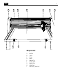
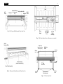
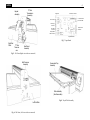
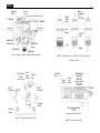
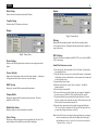
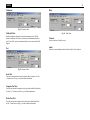
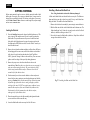
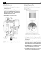
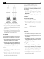
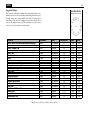
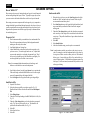
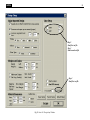
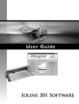
USING YOUR
300 System
Cutter
Copyright © 2002, Ioline Corporation, All Rights Reserved
Printed in the United States of America
PN 107084R3
July, 2002
All Trademarks Are The Property Of Their Respective Owners
Ioline
2
A
H
I
B
E
C
F
D
I
300 System Cutter
A.
B.
C.
D.
E.
F.
G.
H.
I.
Dust Cover
Traverse
Carriage
Keypad
Removable Tray
Fixed Tray (Table)
Right Side Cover
Left Side Cover
Removable tray “Thumb Screw”
G
Ioline
3
Adhesive Sheet
Left
Cover
Traverse
(On Removable
Tray)
Front
Carriage Assembly
Keypad
Right
Cover
Power
Supply
Fig. 1 - 300 System (With Removable Tray) Front View
Logic Board
(See Detail
Below)
“X” Axis
Motor
Assembly
Fig. 3 - 300 Cutter (Bottom View with bottom cover removed)
Serial
Number Plate
Tray strip
(Keeps the removable tray down)
Adhesive
Sheet
Shipping
Screw
Table Assembly
“Y” Axis
drive belt
(Without Removable Tray)
Rear Panel Assembly
Fig. 2 - 300 System (Without Removable Tray) Rear View
Shipping
Screw
Shipping
Screw
Removable tray
thumb screws
Fig. 4 - 300 Cutter (Top View)
Shipping
Screw
Ioline
4
Keypad
Assembly
“X” Axis
Transmission
Assembly
5v Regulator
Parallel Port Connection
“Y” Axis Motor ENC
Fan Connectors
“X” Axis Motor ENC
Power Supply
Connection
Keypad & Serial
Connection
Servo Motor
Connection
Carriage Ribbon
Cable Connection
Programmable ROM
Right End
Plate
Fig. 7 - Logic Board
“Y” Axis
Transmission
Rear Panel
Assembly
Fig. 5 - 300 Cutter (Right view with cover removed)
Belt Tensioner
Assembly
Removable Tray
Assembly
Table Assembly
(Non-Removable)
Left End Plate
Fig. 6 - 300 Cutter (Left view with cover removed)
Fig. 8 - Tray & Table Assembly
Ioline
5
Voice-coil
Wires
Blade
removal pin
Top Spring
Wheel
Main Voice-coil Secondary Voice-coil
“Y” Axis Belt
Blade
holder
body
“Y” Axis Belt
(Push to
remove blade)
Jaw
Flange
Blade holder
thumb screw
Blade Holder
Blade holder
Sensor
Foot “O”
Ring
Foot
Blade
Blade Jaw
Fig. 9 - Carriage Assembly (With Blade holder installed)
Fig. 11 - Blade Holder Assy 1) With foot 2) With foot removed
3) Removing blade
Top Traverse
Wheel
(Spring Loaded)
Flex
Cable
socket
Right side
cover
Carriage
PCB
Belt “T”
Connector
Power
switch
Power
cord
plug in
Parallel cable
receptacle
IEEE-1284
(Commonly called the
“Printer” port)
If Available
Belt “T”
Connector
Traverse
Wheel
Traverse
Wheel
Parallel
port
“Cable
Clip”
Serial cable receptacle
RS-232
(Commonly called the “COM” port)
Fig. 10 - Carriage Assembly (Rear View)
Fig. 12 - Rear Panel Assembly
Ioline
6
Table of Contents
300 System Cutter ................................................ 8
Safety and Precautions ......................................... 8
Installation ........................................................... 9
Unpack the 300 Cutter .............................................................. 9
Prepare the Area ..................................................................... 9
Connect the Cutter to the Computer ........................................... 9
Installing the Hardlock Key ......................................................... 9
Software Installation .......................................... 10
Installing the 301 & Control Center Software ............................. 10
Keypad Controls .................................................. 11
Start/Stop ............................................................................. 11
Arrow Keys ........................................................................... 11
Set Origin ............................................................................. 11
Speed ................................................................................... 11
Force .................................................................................... 11
Test Cut ................................................................................ 12
Repeat .................................................................................. 12
The Ioline Control Center ................................... 12
Changing System Settings ....................................................... 13
Screen Menu Options .......................................... 13
Measurement Units ................................................................ 13
Panel Size ............................................................................. 13
Scale .................................................................................... 13
Update Display ....................................................................... 13
Send Settings to Cutter: Temporary ......................................... 13
Send Settings to Cutter: Permanent ......................................... 13
Acceleration .......................................................................... 13
Up/Down Delays ..................................................................... 13
Force .................................................................................... 14
Blade Overcut ........................................................................ 14
Blade Steering Arc ................................................................. 14
Blade Offset ........................................................................ 14
Minimum Angle ................................................................... 14
Menu Bar Items .................................................. 14
File ....................................................................................... 14
Send Cut/Plot File ............................................................... 14
Open Settings File ............................................................... 14
Save Settings As... .............................................................. 14
Exit .................................................................................... 14
Setup ................................................................................... 14
Plotter Setup ...................................................................... 15
Com Port Setup .................................................................. 15
Display .................................................................................. 15
Plotter Settings ................................................................... 15
Factory Defaults .................................................................. 15
ROM Version ....................................................................... 15
Memory Buffer .................................................................... 15
Blade Holder Status ............................................................. 15
Motor Voltage ..................................................................... 15
Options ................................................................................. 15
Filtering ............................................................................. 15
HPGL Setting... .................................................................... 15
Install New Firmware version ............................................... 15
Calibration ............................................................................ 16
Calibrate Plotter .................................................................. 16
Test ...................................................................................... 16
Serial Test .......................................................................... 16
Computer Port Test. ............................................................ 16
Plotter Port Test. ................................................................. 16
Help ..................................................................................... 16
Contents ............................................................................ 16
About ................................................................................ 16
Cutting Material .................................................. 17
Loading the Material ............................................................... 17
Installing a Blade and the Blade Foot ........................................ 17
Installing a Blade Holder or Pen ............................................... 18
Adjusting Blade Exposure and Force ......................................... 18
Adjusting Blade Exposure: .................................................... 18
Force Adjustment: .............................................................. 19
Verification: ........................................................................ 19
Sending a Cut/Plot File to the 300 System Cutter ....................... 19
Pausing Cutting ................................................................... 19
Canceling a Cut ................................................................... 19
Suggested Settings ................................................................ 20
Advanced Cutting ............................................... 21
How to “KISS-CUT” ................................................................ 21
Communication Testing ...................................... 23
Communication Test ............................................................... 23
Testing the 300 System cutter Serial Port .................................. 23
Testing the Computer Serial Port ............................................. 23
Repair and Maintenance ..................................... 24
Ioline
Cleaning the Traverse Extrusion and Carriage Wheels ................ 24
Cleaning the Blade Holder ....................................................... 24
General Disassembly Procedures .............................................. 25
Removing the End Covers ..................................................... 25
Removing the Bottom Cover for Internal Access ...................... 26
Troubleshooting .................................................. 27
Common Problems ................................................................. 27
Error Messages ...................................................................... 28
Software Errors: .................................................................... 28
L.E.D Codes ........................................................................... 29
Troubleshooting the Parallel Port .............................................. 29
End Notes ............................................................ 30
Getting Help ........................................................................... 30
The FCC Wants You to Know... ........................... 31
Your Comments Are Requested ......................... 31
Customer Service ................................................................... 31
Limit of Liability Statement ...................................................... 31
Index ................................................................... 32
7
Ioline
8
300 SYSTEM CUTTER
SAFETY AND PRECAUTIONS
The Ioline 300 System Cutter provides a simple and economical method for
cutting patterns to be attached to athletic uniforms or other commercial products. The Ioline 301 software provides the fastest possible method for creating
sew disks for automated sewing machines. It also cuts patterns from a wide
variety of file types.
Please read these safety guidelines before beginning operation of the Ioline
300 Cutter. The cutter uses a very sharp blade when cutting. The parts can
move quickly. Always observe the following safety precautions:
This guide will show you how to successfully install and operate these products. By following the instructions, you will benefit from the experience gained
during hundreds of Ioline installations. You will quickly learn how to:
• Cut applique materials using designs from Tajima.Ext, Melco.EXP,
Barudan.DAT or Toyota.10o formats. After sewing, these cut
pieces will be exactly covered by embroidery machine stitches. See
Using 301 Software for more detailed information.
• Cut applique materials from designs created in CorelDRAW or
other compatible software. These cut pieces can then be heat
pressed or sewn onto garments.
• Automatically create sew disks from outlines created in
CorelDRAW. For designs stitched around the outline only, such
as sports lettering, you will find Ioline’s 301 software faster and
easier to learn than most embroidery design software. (If you are
installing the Ioline 301 software without the cutter, proceed
directly to the “Install Software” chapter.)
• Prepare a wide variety of fabrics for successful cutting.
• Control “Puckering”, and “Fraying” in difficult materials.
•Use CorelDRAW to create text and multi color designs.
Important: Before installation, read the installation requirements to make sure
you have everything you will need. When you are ready, follow the installation
instructions step by step. Following these steps will help you save time and
money. For unresolved questions, contact Ioline Tech Support at (425) 3988282, or e-mail to: [email protected].
• Keep your body away from the front of the cutter. The tray moves
freely in this space while the cutter is in operation.
• Do not try to repair the machine without factory authorization. Only
qualified service personnel should attempt any disassembly or access
to internal components. If external mechanical adjustments are
necessary, turn off the cutter and disconnect it from all power sources
(both the computer and the wall outlet).
• Be careful with hair, jewelry, or loose clothing near the machine. Don’t
allow them to become caught in the mechanical parts.
• Never move the carriage (the part that carries the blade holder) or the
tray, by hand while the power is on. Use the Arrow keys and let the
machine do it.
• Keep hands away from the carriage when the cutter is in operation.
• Use caution when changing a blade in the blade holder. See “Installing a Blade & Blade foot” for the recommended procedure.
• Be careful when handling the blades. They are sharp and could cause
an injury if mishandled. Although the blades are made of an extremely
hard material, they are brittle and can break if dropped or mishandled.
Ioline
9
INSTALLATION
Unpack the 300 Cutter
Warning: Do not lift the cutter by the tray, the dust cover, or the carriage rail. This may permanently damage the cutter. Use the bottom
surfaces of the cutter to lift or move it.
1) Inspect the outside of the box first to see if there may be damage to
the machine.
Installing the Hardlock Key
The Hardlock key (common name for this device is a “Dongle”) is a device
that allows you to use the 301 software. Without it, the software will not
work. The Hardlock key comes with the 300 system cutter in the accessory
kit, and plugs into the computer printer (LPT) port. (See Fig. 13 & 14).
Directional Arrow
(This shows the end to plug into the printer port)
2) Carefully remove the cutter from the box and place it on a flatstable surface. This procedure requires two people. Save all packing materials and the box. Check the packing list to ensure that
all of the accessories are present.
Printer Pass-Through
(Allows the printer to be used)
Plug a printer into this end.
3) Look for the 4 (four) screws, one holding each corner of the table
assembly (See Fig. 4 for the location of the table assembly shipping screws). Remove the screws from the table assembly.
Prepare the Area
Prepare a large clean area to work. Make sure the table top is clean and clear
of any obstacles. Pull the cutter away from the wall so the material tray can
move freely in the back.
Connect the Cutter to the Computer
Note: Make sure the computer and the cutter have the power turned
off. Ioline recommends using a surge protector power strip for the
cutter and the computer.
Start by plugging in the 301 “Hardlock” (Dongle) into the Parallel port on the
back of the computer. This is a black box with a 25 pin port on both ends, and
a clear window that says “E-Y-E”. If you have other devices plugged into the
parallel port, the hardlock key can be used as a “Pass-Through” for those
devices.
Connect the 300 System to the computer with the included serial cable. A
serial connection to the cutter is required for correct operation.
The parallel port receptacle on the computer is a 25 pin female receptacle.
The serial port is a 9 pin male receptacle. If the computer has a 25 pin serial
port, a 9 to 25 pin adapter is required. The plotter will not function if a serial
cable is connected to a parallel port.
Printer port Receptacle
Fig. 13 - 301 Software Hardlock Key
Back of computer
Ioline 301 Hardlock “Dongle”
(Be sure to plug in the arrow side to
the printer port)
Printer Cable
(If you have a printer, or
another Dongle you can plug
it into the other end of the
Hardlock)
Fig. 14 - Rear view of computer showing correct installation of the
Hardlock and printer cable.
Ioline
10
SOFTWARE INSTALLATION
Installing the 301 & Control
Center Software
1. Turn on the power to the computer
and start Windows®.
2. Insert the Ioline CD ROM into the
CD ROM drive (usually D:) In
most cases the CD will automatically start to install. Follow the on
screen prompts. If the CD doesn’t
automatically start, continue to
step 3.
3. Select the Start button.
4. Choose Run.
5. Type D:\IOSETUP (substitute the
correct letter if the CD ROM drive
letter is not D:) and Click OK.
6. Follow the instructions that appear
on the screen.
7. Consult the Operation chapter of
this manual for details on using the
Ioline Control Center, or the “301
User Guide”.
Fig. 15 - 301 and Control Center installation screen
Ioline
11
KEYPAD CONTROLS
Set Origin
The Set Origin key sets the initial origin or starting position for
the blade. If a new origin is not set before sending a file to the
cutter, the machine will begin at a point determined by the previous cut file. The software may give the option of selecting this
ending point. The cutter will then treat the new file as a continuation of the previous cut. This will affect the repeat function. Refer
to the Repeat section below. To set a new origin, make sure the
cutter is in Stop mode with the red light on. Use the Arrow keys to
move the pen or blade to the intended origin of the cut, then press
the Set Origin key. The cutter will then accept cut/plot files.
The keypad allows access to the main 300 System functions.
Origin
on Cutter
Fig. 17 - Origin Point.
Fig. 16 - The 300 System Keypad.
Note: Design software usually refers to the origin as “lower left”
because it is the lower left corner of a plot. Because the cut is
usually oriented as shown.
Start/Stop
The Start/Stop key connects or disconnects communication between the computer and the cutter. If the Start/Stop key is pressed
during cutting or plotting (Stop mode) the machine will stop when
the current vector is finished. The Arrow keys are active when in
Stop mode. When the Start/Stop key is pressed again, (Start mode)
cutting will resume exactly where it stopped.
START green light
Arrow keys inoperable, cutter
online (ready to receive instructions).
STOP
Arrow keys operable, cutter off-line
(not ready to receive instructions).
red light
Arrow Keys
Pressing the Arrow keys moves the tray (material) back and forth
or the carriage from side to side. The arrow keys will not work
unless the cutter is in Stop mode (see Start/Stop above).
Origin
in
Corel Draw
Speed
Use the Speed knob on the front panel of the 300 cutter to adjust
the speed. Turn the knob clockwise to increase the speed, or counterclockwise to decrease the speed. Set the speed according to the
type of cutting and material being used. See the Cutting Material
section of this manual.
Force
Adjust the force by using the Force knob on the front panel. Turn
the Force knob clockwise to increase the force exerted on the pen
or blade. See the section on Cutting Material for the recommended
settings. The range of force available at the knob is NOT ADJUSTABLE in the Ioline Control Center.
Note: Using too much force can cause excessive drag, damage
the pen or blade, tear the material, or cut through the adhesive
sheet.
Ioline
12
THE IOLINE CONTROL CENTER
Test Cut
This button will cut a test pattern to help determine the proper
force (for blades or pens) and blade exposure for cutting fabric.
The test cut will also show the effect of the blade offset and overcut
settings in the Control Center. See the section on Cutting Fabric
for details on adjusting force and blade exposure. The Control
Center section has details about blade offset and overcut.
1. Make sure that material is loaded in the cutter that the blade
holder is installed in the carriage. Position the blade over the
material near the right side of the cutter.
2. Check for the red light. Press the Start/Stop key if it is not on.
3. Press the Test Cut key for one second. The plotter will cut a
small test pattern consisting of a circle within a square.
4. Adjust the force and blade exposure up or down with the Force
knob and the blade foot. Repeat the test cut until the desired
line quality is obtained. See the section on Cutting Fabric for
details on adjusting force and blade exposure.
5. Successive test cuts will be automatically aligned to the left of
the last test cut.
6. If the Test Cut key is pressed for three seconds the plotter will
cut a 1.9 in. x 7.1 in. pattern (the Ioline Logo).
The Ioline Control Center is a utility program that does three things:
• It allows adjustment of settings to tailor output from the computer.
• It allows a completed cut file to be sent to the 300 cutter.
• It includes several diagnostic tests for troubleshooting.
Note: To avoid communication port conflicts, do not simultaneously
run more than one application that is communicating with the cutter.
Fig. 18 - Control Center Setup Screen.
Repeat
Pressing the Repeat key will generate one copy of the most recently cut file. The cutter must be in Stop mode (red LED) to use
the Repeat key. To start the cut in a new location, move the pen or
blade to a new position with the Arrow keys before pressing the
Repeat key. Repeat will do the following:
1. Individual files are repeatable until the Set Origin key is pressed
and any new data is sent to the cutter. This includes updating
settings with the Update Display function.
2. If cut files are sent without setting an origin between them, they
will be stored in memory continuously as if they were one file.
This allows the user to repeat multiple files as a single group.
Pressing Repeat will cut all files sent since the last origin was
set (as long as the buffer size is not exceeded, see below).
3. If the file(s) sent exceed the capacity of the buffer (1 megabyte)
before an origin is set the repeat function is disabled. This
feature allows the cutter to handle files of limitless size. When
the buffer has overflowed it no longer holds a complete file so
repeat would produce unpredictable results.
Note: If an origin is not set between files, two possible unintended
results can occur: if the combined cuts do not exceed the buffer,
repeat will cause them all to be recut or, if the combined files
exceed the buffer size, repeat will be disabled.
Fig. 19 - Control Center Main Menu.
Ioline
13
Changing System Settings
A variety of settings are adjustable to fit specific needs:
• The 300 cutter must be in Start mode (green LED on) when changing
system settings. Press the Start/Stop key and make sure the green keypad
light is on before changing any settings.
• The Screen Menu displays the primary settings that are adjustable. The
Menu Bar contains utilities and less common cutter settings.
• The selected changes will be in effect only after one of the Send Settings
buttons is pushed.
Note: Some design software may to override the Control Center settings. Check to see if it has by pressing the Update Display button
before and after a cut is completed. If the settings change, use the
design software to modify cutting parameters.
SCREEN MENU OPTIONS
Measurement Units
English or Metric units are available when adjusting settings.
Panel Size
Update Display
Note: The design software may override the Control Center settings.
Check to see if it has by pressing the Update Display button before and
after a cut is completed. Check the plotter setup screens in the design
software to make adjustments if necessary.
Selecting this option will update all of the screen values with the current
settings stored in the cutter. For example, using Update Display after a blade
is inserted in the carriage will update the Control Center force settings.
Send Settings to Cutter: Temporary
After changing any settings on the screen, the changes must be sent to the
cutter. If Send Settings to Cutter: Temporary is selected, all of the displayed
settings will be used for the current session. When the cutter is turned off these
settings will be lost and the previous permanent settings will be in effect
when the cutter is turned on again. If any settings are changed, repeat the Test
Cut procedure to ensure that the results are satisfactory.
Send Settings to Cutter: Permanent
If Send Settings to Cutter: Permanent is selected, all of the displayed settings will be sent to the cutter and are saved for all subsequent sessions, even
after turning off the cutter.
Acceleration
The Panel Size is the maximum area the cutter can use for cutting. The factory
set (and maximum) X-axis panel length is 18.25 inches long (50 cm). The
maximum Y-axis panel size is 32.25 inches. The material moves along the Xaxis; the carriage moves along the Y-axis.
The factory set acceleration is 1.0 g. The acceleration setting determines how
quickly the pen or blade will reach full speed when starting or ending a cut line.
Use the Control Center to change the setting within a range of 0.1 to 1.0 g. For
time consuming or difficult cuts, or when trying to achieve maximum accuracy,
use lower acceleration settings.
Scale
Up/Down Delays
The factory-set Scale is 100%. The cutter will produce a cut in the exact size
of the cut file that is sent. If the scale is 50%, the cutter will produce a cut that
is half the file size. The scale of the cutter can range from 1% to 999%. Note:
Both X and Y axes are set independently.
The factory setup and down delays are both 0 milliseconds (ms) or 0 thousandths of a second. The delay setting controls the amount of time, in milliseconds, the cutter pauses after lifting or lowering the pen or blade. Under
normal circumstances this setting will not require adjustment. Thick material
(e.g. Felt) may require a delay of 25 to 50 ms.
Ioline
14
MENU BAR ITEMS
Force
The minimum and maximum force settings for the Force control knob on the
keypad are adjustable by turning the knob, but in the Control Center the
values are fixed. The factory set and default minimum is 10 grams. The maximum value is 700 grams.
Blade Overcut
Blade overcut is the distance the blade travels beyond the end of a cut. Blade
overcut ensures that each cut actually reaches the point where one cut line
meets and slightly overlaps another cut line. This ensures that all of the pieces
of the design are cut completely, with no undercuts. The factory set blade
overcut is 10 mils. This setting is ignored when a pen is installed in the
carriage.
The menu items along the top of the screen allow adjustment of a variety of
settings for computer control of the Ioline plotter. File management, plotter
setup and serial port testing can all be accessed from the menu bar.
File
Blade Steering Arc
Blade Offset
The blade offset is nominally .094 mils, but specific blades can vary within a
tolerance. For close work, making some tiny test cuts at several settings, then
picking the best one, can improve accuracy. This setting is ignored when a
pen is installed in the carriage.
Minimum Angle
This is the minimum angle for which the signcutter blade will perform a blade
steering arc. For a very tiny cut, a small or zero angle can be specified. For
larger cuts a greater angle of up to 45 degrees is best. The factory set value
works well with most files. Adjusting this setting for small cuts may improve
performance. This setting is ignored when a pen is installed in the carriage.
Fig. 20 - File Menu
Send Cut/Plot File
Use this option to send plot files (.plt format) to the 300.
Open Settings File
Opens custom settings for the 300 that have been stored with the Save
Settings As... option below. Once the settings file is loaded use the Send
Settings buttons described in the Screen Menu Options Section.
Save Settings As...
Allows custom settings to be saved to a file so that they can be sent to the
300 at a later time. To retrieve these files use Send Settings File
explained above.
Exit
Close the Ioline Control Center.
Setup
Fig. 21 - Setup Menu
Ioline
15
Options
Plotter Setup
Allows selection of the plotter model and COM port.
Com Port Setup
Provides a list of COM ports to select from.
Display
Fig. 23 - Options Menu
Filtering
Displays the filtering dialog window. Some files don’t produce quality
curves and line structure. Enabling the filtering option helps to smooth out
some of these lines.
Fig. 22 - Display Menu.
HPGL Setting...
Plotter Settings
Allows the 300 cutter to switch between HPGL/7475 (Lower Left), and HPGL/
7596 (Center origin).
Replaces all of the Displayed values with the current settings stored in the
plotter.
Install New Firmware version
Factory Defaults
Replaces all of the Displayed values with the factory defaults. A dialog box
will appear that allows these values to be sent to the plotter.
ROM Version
Displays the current ROM version installed in the plotter.
Memory Buffer
Displays the amount of buffer memory on the logic board. This value
should be 1024 K (1 Meg)
Blade Holder Status
Displays whether or not the blade holder is installed.
Motor Voltage
Displays the voltage of the motors that are installed in the 300 cutter. This
option will only work with ROM version 106882 r0 and higher.
1) Turn the cutter on, and let it initialize. Press “Set Origin”, the light on the
keypad will turn Green.
2) Copy the file that was sent to you by Ioline Tech Support or downloaded
off the Ioline web site to the hard drive of the computer that is connected
to the 300 System Cutter.
3) Open the Ioline Control Center.
4) When the Control Center is open, Click on “Options”/ “Install New
Firmware Version”.
5) Click on “Begin Version Install”.
6) The next window shows the file structure on your computer. Find the file
that was sent to you (.BIN file). Click on the file, and click on “OK”.
7) The plotter will make a beep sound, and the light will turn off. The new
firmware will now start to load into the plotter. When it’s done, close the
Ioline Control Center, and turn the plotter off.
8) Reset the plotter by turning it back on while pressing and holding the
“UP” arrow key on the keypad of the 300 System. The button can be let
go when the carriage starts to move to the left.
Note: After the 300 cutter is reset back to factory defaults any user settings
(such as Acceleration, Up & Down Delay, Blade offset and Angle) ,
and calibration are reset. If you need to re-calibrate the machine See
‘Calibrate Plotter’ on Page 16.
Ioline
16
Calibration
Help
Fig. 24 - Options Menu
Calibrate Plotter
Fig. 26 - Help Menu
Provides methods to calibrate the cutter for maximum accuracy. The 300
System is calibrated at the factory, and does not need dimensional calibration. If you feel the cutter is not dimensionally accurate, contact Ioline Tech
Support.
Contents
Lists the contents of the help screen.
About
Test
Provides revision information about the Ioline Control Center software.
Fig. 25 - Options Menu
Serial Test
Tests the serial connection between the plotter and the computer. See the
“Communication Testing” section for further information.
Computer Port Test.
Tests the serial port on the computer with a special tool available from Ioline.
See Page 26, “Communication Testing” for further information.
Plotter Port Test.
Tests the serial port on the plotter with a special tool available from Ioline.
See the “Communication Testing” section for further information.
Ioline
17
CUTTING MATERIAL
Before cutting material, turn the cutter on, load the material, install a blade
holder, and set an origin. These steps are outlined below. In most cases the
design files are sent directly from the 301 software to the plotter. If necessary,
use the Ioline Control Center software to send design files, adjust settings
and test cutter communication.
Loading the Material
1)
Press the Start/Stop button on the keypad, until the light turns red. The
cutter is now off-line and the arrow keys can be used to position the
blade holder. The up and down arrow keys move the table back and
forth, while the left & right arrow keys move the carriage side to side
(the light must be RED for this to work). Press the “Down” arrow key to
move the table forward.
2)
Remove the tray from the machine and place on a flat surface. Pull away
the backing paper from one corner, and feel the adhesive on both sides
of the sheet. One side is stickier than the other (Light Tack Sheet
ONLY), place the “Stronger” adhesive side on the tray. There are corner
guides on the front edge of the tray to help during placement.
3)
Remove the paper cover sheet from the adhesive sheet on the
removable tray. Note: Keep this cover sheet clean so you can reapply it
after you are done cutting for the day. This cover keeps dust, fibers,
and air away from the adhesive surface. When not in use this will
extend the life of the adhesive sheet.
4)
Put the material you wish to cut on the adhesive surface and press it
down a little at a time, starting at one end and pushing out any bubbles
as you go. Caution: Make sure the material being cut does not extend
beyond the edge of the table where it could get caught up with the
workings of the cutter. DO NOT cut regular paper, cardboard, or any
material with many loose fibers on the bottom side (adhesive side).
Such materials will stick permanently to the adhesive surface,
reducing the life of the adhesive sheet.
5)
Place the removable tray in the table assembly, and tighten the thumb
screws on the front of the removable tray.
6)
Locate the blade holder in the accessory kit of the 300 cutter.
Installing a Blade and the Blade Foot
Note: Using a hard surface to insert the blade may damage it.
A blade and a blade holder are included in the accessory kit. The blades are
sharp and the tips can chip or break very easily. Be very careful when handling the blades. To install the blade and blade foot:
1. Remove the foot from the assembly by unscrewing it counterclockwise.
2. Slide the blade into the hole in the blade holder until it bottoms out. The
blade should spin freely. Notice the pin on the other side of the blade
holder, it should be sticking out about 3/16”.
3. Screw the foot onto the blade holder (clockwise). Stop before the blade
emerges from the hole in the foot.
Foot
Fig. 27 - Installing the Blade and the Blade Foot.
Ioline
18
Installing a Blade Holder or Pen
Adjusting Blade Exposure and Force
1. Rotate the thumb screw on the carriage until there is enough room to
insert the blade holder or pen.
Properly adjust blade exposure and force to achieve good cutting results.
Adjusting Blade Exposure:
2. If using a blade holder or plotter pen, slip the flange into the slot in the
carriage jaw. If using a regular pen, position the tip 1/10 inch off of the
platen when the jaw is in the up position. The cutter can hold any pen
with a maximum barrel diameter of 7/8” (22 mm).
3. Tighten the thumb screw until the blade or pen is secure.
Adhesive
Sheet
Blade
Material
Foot
Fig. 29 - Proper blade exposure that lightly scores the backing.
Thumb Screw
Blade Holder
Fig. 28 - Blade Holder in the Carriage Jaw. Note: Carriage is shown with
cover removed
1. On the keypad, turn the Force knob clockwise to maximum. Set the
Speed to 50%. The maximum force setting is 700 in the Control Center
and is not adjustable.
2. Check that the blade tip is not visible when viewing the blade from the
side. This technique approaches the correct blade exposure from too
little with no chance of having too much (which could damage the blade).
3. Press the Start/Stop button on the front panel until the LED is red. Move
the carriage until the blade is near the right edge of the material.
4. Press the Test Cut key for one second. The cutter will cut a test cut pattern.
There will be no cutting if the initial foot adjustment was correct.
Ioline
19
Sending a Cut/Plot File to the 300 System Cutter
Always load the cutter and make test cuts to determine the correct settings
before sending any files. See the Adjusting Blade Exposure and Force sections for more details.
Important: Make sure that the carriage and material are in the proper
position and that an origin is set by pressing “Set Origin” on the keypad (LED is green).
Send the file directly from the 301 software following the directions in the
301 User Guide or;
From the Ioline Control Center Software:
1. From the menu bar select File, Send Cut/Plot File.
Less Blade Exposure
More Blade Exposure
Fig. 30 - Turning the foot to add or subtract blade exposure.
5. Turn the foot 1/8 turn upward (clockwise from below). Press the Test Cut
key. Note: Successive cuts will automatically be positioned to the left of
the previous test cut.
6. Continue increasing the blade exposure and making test cuts. The test
design will completely separate from the surrounding material and lightly
score the adhesive sheet when enough blade is exposed.
Force Adjustment:
Every type of material requires different cutting force. Before adjusting force
make sure that the blade exposure is adjusted first. See instructions above.
1. Turn the force knob down slightly from maximum, about one mark, and
repeat the test cut. Use full force if the test cut is not complete.
2. If the test cut is complete, turn the force down again and repeat the test
cut. Continue until the cut is incomplete. This indicates that there is not
enough force to push the exposed blade fully into the material. At this
point turn the force knob up one mark, which is just enough.
Verification:
1. Press the Test Cut key for 3 seconds. The cutter will cut a 1.9 inch x 7.1
inch design (the Ioline logo).
2. If the sign does not separate cleanly and leave a light scoring on the
adhesive sheet, try another 1/8 turn upward (counter clockwise from
above) of blade exposure and a very slight increase in force.
2. Either enter the path and file name of the cut or select the correct location
from the directory\file lists in the dialog box. For example, the path
might be:
C:\IOLINE\<filename>.plt.
4. Select OK.
Pausing Cutting
1. Press the Start/Stop key to place the signcutter in Stop mode (red LED).
2. When cutting is interrupted, the carriage and material can be moved with
the keypad Arrow keys.
3. Press the Start/Stop key to resume cutting. The 300 Cutter will return to
the original cutting position and continue plotting where it stopped. The
keypad LED will change from red to green.
Canceling a Cut
1. Press the Start/Stop key to place the 300 in Stop mode (red LED).
2. Cancel the cut from the design software (refer to the design software
manual or consult software dealer) or cancel the cut in the Control Center
software by clicking on the Abort button in the Send File window. Note:
If this step is skipped the cut will continue when a new origin is set.
3. Press the Set Origin key to make the signcutter delete the cut data it has
already received but has not yet plotted.
Ioline
20
Speed & Force
Suggested Settings
There are many variables that determine cutter output quality. Ioline recommends using low force and speed settings when making the initial test cuts.
Gradually increase these settings until the best values for the material are
found. Refer to Table 1 below for settings for a variety of material types. Force
values are for starting reference only. These settings may vary due to manufacturer, color, age, and temperature of the material.
(Settings relate to a clock)
Material
Thickness
Blade
Stahl's Tackle Twill (with heat sensitive backing)
Stahl's Tackle twill (with Pressure sensitive backing)
Stahl's Thermal Film
Stahl's Thermal Flock
Elastic Twill
Cotton Acrylic
Rayon
Felt (Without backing)
Soft Felt (without backing)
Soft Felt (With Backing)
Felt (with backing)
Foam Fabric
Light Canvas
Stretch Knit Fabric
Thin Textile Suede
Medium Textile Suede
Imitation Suede
Strap Twill
Ideal Stencil "Oil-Board"
Stencil Mask
Neon Mask
Transparency Film
16 mils
16 mils
7 mils
25 mils
15 mils
11 mils
27 mils
23 mils
37 mils
26 mils
43 mils
31 mils
18 mils
19 mils
38 mils
40 mils
19 mils
24 mils
17 mils
11 mils
8 mils
5 mils
30/45 degree
30/45 degree
45 degree
45 degree
30/45 degree
30/45 degree
30/45 degree
30 degree
30 degree
30 degree
30 degree
30 degree
30/45 degree
30 degree
30/45 degree
30/45 degree
30/45 degree
30/45 degree
45 degree
45 degree
30/45 degree
45 degree
Fig. 31 - Suggested Settings for Different Material Types.
Acceleration
1.0
1.0
1.0
1.0
0.5
0.5
0.5
0.5
0.5
0.5
0.5
0.5
0.5
0.5
0.5
0.5
0.5
0.5
1.0
1.0
1.0
1.0
Speed
5:00
5:00
12:00
12:00
10:00
9:00
8:00
10:00
10:00
10:00
12:00
12:00
1:00
9:00
2:00
5:00
5:00
9:00
5:00
5:00
5:00
5:00
Force
1:00
1:00
11:00
11:00
3:00
2:00
3:00
5:00
5:00
3:00
3:00
2:00
5:00
12:00
12:00
2:00
2:00
5:00
5:00
5:00
12:00
9:00
Ioline
How to “KISS-CUT”
21
ADVANCED CUTTING
Kiss cutting is the process of cutting through one layer of a stack of material
and not cutting through the layer(s) below. Typically the upper layer(s) has
a pressure sensitive backside which adheres to the lower layer of material.
Kiss cutting creates more scrap material for the upper layer(s), (compared to
cutting individual layers and hand placing them on the lower layers) but can
result in a considerable time savings since multiple layers do not need to be
aligned and the placement stitch for the upper layer may be eliminated from
the embroidery process.
Send second cut file
1.
2.
3.
Prepare to Cut
1. Place bottom material layer onto adhesive sheet and smooth it flat.
Place the foreground material on top of the background material
making sure the sticky side is down.
2. Load blade holder into Carriage Jaw.
3. Adjust Blade Holder as described in the quick start guide, or the
previous section. (Test with single button test cut.) Adjust blade
exposure and cutting force so that only the material is cut. Weed
the test cut, the bottom layer of twill should be scored lightly. If it
cuts through both layers the blade is out too much.
Note: It is recommended that the materials are of similar type and
thickness so the blade does not need readjustment.
4.
5.
6.
When the first cut is done, press the Start/Stop button (the light
should turn “Red”) and move the tray forward. Weed away the
excess material around the top letter.
Press Start/Stop button on the keypad, the light should turn back
to green and the tray and head will move back to the original
starting point.
Under the Color Setup heading, select the color that corresponds
to the next layer of the design to be cut and deselect the color that
was just cut. This profile should have a larger outline than the one
previously cut.
Select OK.
Select Send to Cutter.
After it has finished cutting, weed away the excess material.
Note: As an alternative method, you can also cut the pieces in reverse
order. For example, cut out the background piece(s) first, then lay
the top piece of fabric on and cut those pieces out. This method
allows you to 1) cut a whole tray of Kiss-Cuts, and weed the two
pieces of fabric together, 2) No blade foot adjustment required for
each layer, 3) Can be cut normal, or mirrored if all you have is twill
with a paper backing.
4. Once blade is adjusted, use the keypad Arrow keys to position the
Table and Carriage so that the Blade Holder is over the lower right
corner of the material (lower left origin of plot file).
5. Press Set Origin on the Keypad to obtain a green keypad light.
Send first cut file
1.
2.
3.
4.
5.
6.
7.
8.
Open the 301 software.
Select the directory and file you wish to open (See Fig. 33).
Double click on the file or select the file and click on Load Import
File.
Select Design Setup.
Under the Color Setup heading, select K-C ALL (Kiss Cut All). (See
Fig. 33)
Under the Color Setup heading, select the color that corresponds
to the “Top” layer of the design to be cut. This should be the
profile with the smallest outline. (See Fig. 33)
Select OK.
Select Send to Cutter.
Select OK.
Fig. 32 - 301 “Main” Window
Ioline
22
Step 5
Send first cut file
Step 3
Send second cut file
Step 4
Send first cut file
Fig 33 - Ioline 301 “Design Setup” Window
Ioline
23
COMMUNICATION TESTING
There are three communication diagnostic tests available in the Control Center. These tests are designed to help determine if a communication problem
exists and to isolate where the problem is occurring.
A diagnostic module is required to run two of these tests. It will work on both
the computer and signcutter serial (COM) ports. It is available from Ioline or
an authorized dealer.
Communication Test
This test will determine if communication is working between the computer
and the plotter on the parallel (LPT) or serial (COM) ports. Run this test from
the Control Center, Test menu. The diagnostic module is not required to run
this test.
1. Turn the plotter off. Connect the plotter to the computer with either a
serial or parallel port cable. See the section Connect the 300 System
cutter to the Computer in the Installation chapter for more details.
2. Start the Ioline Control Center. Select Test, Communication Test from
the menu bar at the top of the window.
3. Turn on the 300 cutter while holding down the Test Cut key on the
keypad. Hold down the Test Cut key until the cutter beeps and the light
flashes three times. The machine is now in Test Mode.
Testing the 300 System cutter Serial Port
The diagnostic module is required for this test.
1. Connect the diagnostic module directly to the 300 cutter COM port
(bottom).
2. From the Control Center main menu, select Test, Plotter Port Test.
3. Turn on the cutter while holding down the Test Cut key on the keypad.
Hold down the Test Cut key until the cutter beeps and the light flashes
three times. The cutter is now in Test Mode.
4. Press any Arrow key on the keypad to transmit and receive characters.
Verify that the cutter beeps.
5. Turn off the cutter at the end of the test. This will exit Test Mode. If this
test fails, the cutter port is faulty.
Testing the Computer Serial Port
The diagnostic module is required for this test.
1. Connect the diagnostic module directly to the COM port on the computer. If the computer COM port has a nine pin connector, use a 9 pin to
25 pin adapter between the COM port and diagnostic module.
2. From the Control Center main menu, select Test, Computer Port Test.
4. If testing the serial (COM) port, press the Start/Stop key on the cutter and
verify that the handshake line (CTS) status displayed on the computer
screen toggles On/Off. Leave the handshake line On. This is not necessary for the parallel (LPT) port.
3. Verify that the COM port selected is the correct one. If it is not, select the
proper COM Port.
5. Press the Repeat key to switch the cutter into Echo mode. The green light
will come on.
5. Press any key on the computer keyboard and verify that the character
transmitted equals the character received.
6. Press a key on the computer and verify that the character transmitted
equals the character received. If the characters match then the connection
between the cutter and computer is working properly.
6. Select the Exit button at the end of the test. This will exit Test Mode. If
this test fails, the computer port is faulty.
7. Select Exit after the communication test is complete.
8. Turn off the cutter at the end of the test. This will exit Test Mode.
9. The next two tests are not necessary if serial (COM) port testing is successful.
4. Verify the CTS handshake line is on.
Ioline
24
REPAIR AND MAINTENANCE
Cleaning the Traverse Extrusion and Carriage Wheels
As dust and debris accumulate on the traverse extrusion it will have to be
wiped off with an isopropyl (pharmacy) alcohol dampened, lint-free cloth.
With a clean cloth dampened with Isopropyl alcohol wipe the traverse
extrusion where the carriage wheels ride on the rail. Move the carriage side
to side while wiping the traverse so as to clean the entire surface. See the
first figure at the begining of this guide for the location of the traverse
extrusion.
Cleaning the Blade Holder
When the machine cuts twill or any other soft weave fabric the blade holder
has a tendancy to build up “Fuzz” in the hole where the blade rotates. The
blade itself is described as a “Drag Knife”, and must rotate in the holder
without restriction in order for it to cut properly. Remove the blade holder
after each sheet of fabric, and remove any fuzz build up. This will ensure the
cutting quality will not be affected by the blade rotation.
Fig 35 - A clean blade holder
Fig 34 - Cleaning the traverse extrusion
Fig 36 -After several sheets of twill without cleaning
Ioline
25
Front cover screw
(left side)
General Disassembly Procedures
Rear cover screw
(left side)
The following procedures describe the basic disassembly of the 300 system
cutter to gain access to the keypad, power, and drive components. Please
pay close attention to the Warning and Caution notes.
Removing the End Covers
1.
2.
3.
Turn off the 300 and unplug the computer data, and power cables.
Remove the two black phillips head screws, and the single silver phillips
head screw on the bottom of the cover, then remove the right cover. To
access the rear black screw, you may have to move the tray forward. See
figure 37 below.
Remove the two black phillips head screws, and remove the left cover.
See figure 38 on the next page.
Fig 38 - Left side cover screws (Black phillips head)
Rear cover screw
(Right side)
Front cover screw
(Right side)
Move cover to the
right, and rotate to
the front when it
reaches the keypad
control knobs
Fig 37 -Right side cover screws (Black phillips head)
Fig 39 - Removing the right side cover
Ioline
26
Bottom Cover
Removing the Bottom Cover for Internal Access
WARNING
•
The 300 system cutter is very heavy and could cause an injury if it
falls. Make sure that another person assists with moving the cutter.
When the bottom cover of the 300 is removed and the power is on
there is an electric shock hazard. These diagnostic procedures should
only be performed by qualified technical personnel or individuals
that are aware of safe practices with 110 VAC and 220 VAC devices.
•
Do not lift the 300 by its top dust cover, or the tray
assembly. Use the bottom surfaces of the end plates for
lifting and moving the plotter.
Right side cover
under the tray
Fig 40 - Turn the 300 over, and place right side cover under tray
Tools Required:
•
•
•
Phillips head screw driver.
Two people capable of lifting 50 pounds each.
Grounding strap (optional).
Perform the Following Disassembly:
1.
2.
3.
4.
5.
6.
Turn the power off, and disconnect the computer data, and power
cables.
Move the carriage assembly to the right side of the cutter.
Remove the right side cover. See Removing the covers earlier in this
guide.
Use your assistant to help you flip the 300 cutter over onto it’s top
dust cover. Use the right side cover to place under the tray so it
doesn’t fall over while it’s on it’s top. See fig. 40
Remove the phillips screws along the bottom cover’s edge. See Fig.
41
While removing the bottom cover, take care in unplugging the fan wire
from the logic board
Important: Call Ioline Customer Service or consult the 300 Service Manul
before proceding any further.
Bottom cover screws
Fig 41 - Bottom cover screws
Ioline
27
TROUBLESHOOTING
If the system is not working correctly the problem could be with the
computer, the cable, the design software, or with the cutter. Changes to the
computer operating system or the installation of new peripherals or
software might cause conflicts. If the computer or the design software
cause a problem, consult the computer or software manuals or call the
manufacturer or dealer.
If the problem is with the cutter, begin by making sure power is on and that
the cable between the machines is connected correctly. Test the connection
with the methods described in the Communication Testing section. Consult
the following chart for more detailed troubleshooting techniques:
Common Problems
Problem
Cause
Solution
The cut file doesn't start in the correct
place on the tray.
The "Origin" has not been set.
Press the "Set Origin" button on the
keypad with the blade positioned
where the cut file should start.
A file has been sent from the
software, but the 300 won't cut.
A communication problem has
occurred or the 300 is in "Stop" mode
(red LED).
Make sure the serial or parallel port
on the computer and the 300 are
configured properly. Or press the
"Start/Stop" button on the keypad
to obtain a green LED.
Ioline
28
Error Messages
Error messages that are specific to the 300 are divided into two categories;
software errors and LED codes. Software errors present themselves on the
computer screen and usually indicate a communication problem. LED codes
are visible below the keypad on the front panel of the 300 and can be green,
red or a combination of both. The LED code table in this section is for
finding the cause of obvious external or communication problems. Later in
the chapter a more comprehensive LED index is available for complex
mechanical and electronic difficulties. Other errors can occur with the
operating system or the design software and should be resolved with the
software vendor.
Software Errors:
Error Message
Problem
Solution
Could not open COMx or LPTx
The software could not locate the cutter Verify the cutter is connected to that
on the specified COM or LPT port.
port, or check that the operating system
recognizes the port.
Green light not on or cutter not connected The software opened the port but could Be sure the cutter is connected to the
to COMx or LPTx
not get a response from the cutter.
selected port, that the cutters green LED
is on, and that the cable connecting the
computer to the cutter is functioning.
Due to the nature of serial and parallel
communication, it is possible to get this
message if an attempt is made to interact
with the cutter while it's cutting. If this is
the case, wait for the 300 to finish
cutting and send the file again.
Setup COM port and check plotter present. The last operation requires that the
Be sure the cutter is connected to the
plotter be connected to the port but the selected port, that the cutters green LED
software could not find it.
is on, and that the cable connecting the
computer to the cutter is functioning.
The plotter that you selected is not the
same as the one connected to your
computer.
The Control Center cannot match the
Select the correct plotter from the list.
cutter that was chosen at the start up
with the one found during initialization.
Ioline
29
L.E.D Codes
Troubleshooting the Parallel Port
(Only available on some cutters with a parallel port on the back)
LED Sequence
3+ Second
pause then
repeat
Problem
1. Buffer Overflow
2. Communication Problems
3. Defective RS-232 Chip.
Outdated Firmware.
3+ Second
pause then
repeat
Solution
1. Perform cutter reset.as outlined later in
this chapter.
2. Perform communication test as
outlined later in this chapter.
3. Replace the RS-232 chip.
Check the Firmware version, install
firmware if needed. Contact Ioline Tech
Support
1. Click the Start button, select Settings and then click Printers to open the
Printers window.
2. Right Click the printer icon for a network printer and select Properties.
3. Click on the ‘Capture Settings’ or ‘Details’ tab.
4. Click on ‘End Capture’. Select LPT 1 and click ‘OK’.
Plotter Language syntax error
The file being sent to the cutter is not of
the same language that the cutter is
looking for. Open the Ioline Control
Center, and run a test file. If the error
doesn't happen again, check the original
file for problems.
Carriage ("Y" axis) jam.
Check to make sure the carriage moves
side to side freely, and remove all objects
causing the jam to occur.
Table ("X" Axis) jam
Check to make sure the tray moves in and
out freely, and remove any objects
causing the jam to occur.
1. Click the Start button, select Settings and then click Control Panel to
open the Control Panel window.
Logic Board Error
Call Customer Service
2 Double Click the System icon to open the System window and then click
the Device Manager tab.
Constantly
Repeating
3+ Second
pause then
repeat
3+ Second
pause then
repeat
2 Red Flash
2 Green Flash
repeat
5. Assign the network printer path to another parallel port designation like
LPT 3. Set the printer to use that port or select a network print que path.
BIOS settings can also have an effect on parallel port performance. The cutter
supports only SPP, or Normal parallel port communication. ECP and EPP
modes are not supported. These instructions include editing the PC BIOS to
ensure that the port is in the proper mode prior to staring Windows.
3. Remove the parallel port by clicking Ports, selecting the port and clicking the Remove button.
4. Shut down Windows.
5. Restart or Reset the computer.
Le ge nd
Solid GREEN Light Emitting Diode (LED)on the keypad
6. Enter the PC BIOS setup. This is usually done by hitting the DEL, F1 or
ESC key during the boot sequence. Consult the computer manuals or
contact the manufacturer for more information about entering BIOS setup.
Blinking GREEN Light Emitting Diode (LED) on the keypad
7. Find the parallel port setup options and set the port to be SPP, or Normal
(not ECP or EPP). Also, make sure there is no DMA activity over with the
port.
Blinking RED Light Emitting Diode (LED) on the keypad
8. Save the BIOS settings and exit setup.
9. Restart the computer and allow Windows to start up. Windows should
find the port and install it using the new settings.
Ioline
30
END NOTES
Please gather the following information about your cutter before contacting Ioline for technical support.
Getting Help
Ioline is committed to providing the highest quality service and support to its
customers. If you need assistance with an Ioline cutter, a number of resources
are available:
1. First, refer to this User Guide for answers to your specific questions.
Name:
Company Name:
Phone Number:
Fax:
2. Consult the support section of the Ioline web site: www.ioline.com.
Model:
3. For additional assistance, contact the dealer you purchased the machine
from. Contact information is listed on the last page of this User Guide.
Any warranty servicing of this product not specifically described in this manual
must be authorized in writing by Ioline Customer Service. You may obtain
service by calling or faxing Ioline Customer Service. The technicians will
help you determine the nature of the problem. If factory repair is necessary,
you will receive a RMA (Return Material Authorization). Please gather the
information indicated in the next column before contacting Ioline or your
dealer.
Serial Number:
Date of Purchase:
Dealer:
Type of Material Used:
1. Carefully package the 300 System cutter in its original container or equivalent. You may purchase shipping containers from Ioline by contacting
Ioline Customer Service. Ioline is not responsible for any damage due
to inadequate or improper packaging.
Type of Computer:
2. Carefully wrap and secure all items in the shipping container to prevent
damage. Seal the container and note the RMA near the address block.
New Software or Peripherals:
3. Ship the container using FED-EX or another approved carrier. COD SHIPMENTS ARE NOT ACCEPTED. You will be contacted prior to the start
of work with an estimate of repair cost. All repairs are warranted for 90
days.
Type of design software:
Service History (if any):
Note: Ioline Customer Service contact information is listed on the last
page of this section.
Ioline
31
THE FCC WANTS YOU TO KNOW...
YOUR COMMENTS ARE REQUESTED
This equipment generates and uses radio frequency energy and, if not installed and used properly (in strict accordance with manufacturer instructions), it may cause interference to radio and television reception. Operation
is subject to the following two conditions: (1) This device may not cause
harmful interference, and (2) this device must accept any interference received, including interference that may cause undesired operation. If this
equipment does cause interference to radio or television reception - which
can be determined by turning the equipment off and on - you are encouraged
to try to correct the problem by one or more of the following measures:
Ioline Corporation is interested in comments on our documentation and products. Please send corrections or suggestions to:
• Use only shielded interface cables.
• Reorient the receiving antenna.
• Relocate the host computer with respect to the receiver.
• Move the host computer away from the receiver.
• Plug the host computer into a different outlet so that the host computer
and receiver are on different branch circuits.
If necessary, consult the dealer or an experienced radio/television technician
for additional suggestions. The following booklet, prepared by the Federal
Communications Commission, is a helpful reference:
How To Identify and Resolve Radio-TV Interference Problems:
The stock number is: 004-000-00345-4
This booklet is available from:
U.S. Government Printing Office
Washington, D.C. 20402
IOLINE CORPORATION
14140 NE 200th Street
Woodinville, WA 98072 USA
Voice: (425) 398-8282
Fax: (425) 398-8383
www.ioline.com
[email protected]
This User Guide is provided for informational purposes only. The contents are
subject to change without notice, and Ioline Corporation assumes no responsibility for any errors that may be contained herein. No part of this User Guide
may be copied, disseminated, or distributed without the express written consent of Ioline Corporation.
Customer Service
Ioline Corporation is committed to providing quality service and support to
our customers. If you need assistance with an Ioline product, contact your
local dealer or Ioline authorized service center. You may also contact the
Ioline Customer Service Department
Monday through Friday
7:00 A.M. - 5:00 P.M. U.S. Pacific Time
Voice: (425) 398-8282
Fax: (425) 398-8383
[email protected]
www.ioline.com
Ioline has many years of experience working with designers. Feel free to
contact us if you have questions or to share information.
Limit of Liability Statement
It is the responsibility of the operator of the cutter to monitor the performance
of the cutter and maintain it in proper working condition by following the
instructions in this User Guide. It is the responsibility of the operator of the
cutter to follow all safety precautions and warnings that are described in this
user guide. Ioline is not responsible for injuries that may occur as a result of
unsafe operating procedures. Ioline is not responsible for substandard operational performance as a result of failure to maintain the cutter as described in
this user guide.
Ioline
32
INDEX
F
About 16
Acceleration 13
Adhesive Sheet 3
Arrow Keys 11
Factory Defaults 15
File 14
Filtering 15
Fixed Tray 2
Force 11, 14, 18, 20
Force Adjustment 19
B
H
Blade Foot 17
Blade Holder 18, 24
Blade holder 5
blade holder 17
Blade Holder Status 15
Hardlock 9
Help 16
Holder Status 15
HPGL Setting... 15
A
C
Calibrate Plotter 16
Calibration 16
Carriage 2, 18
Carriage Jaw 18
Carriage Wheels 24
Color Setup 21
Com Port Setup 15
Communication Test 23
Computer Port Test. 16
Computer Serial Port 23
Contents 16
I
Install New Firmware version 15
K
Keypad 2, 3, 11
KISS-CUT 21
L
L.E.D Codes 29
Left Cover 3
Load Import File. 21
Logic Board 3
D
M
Design Setup. 21
Display 15
Dongle 9
Dust Cover 2
Measurement Units 13
Memory Buffer 15
Minimum Angle 14
Motor Voltage 15
E
O
End Covers 25
Error Messages 28
Exit 14
Exposure 18
Open Settings File 14
Options 15
Overcut 14
P
Panel Size 13
Ioline
Parallel Port 29
Parallel port 5
Permanent 13
Plotter Port Test. 16
Plotter Settings 15
Plotter Setup 15
Power Supply 3
Power switch 5
R
Rear Panel Assembly 3
Removable tray 2
Repeat 12
Right Cover 3
Right Side Cover 2
ROM Version 15
S
Save Settings As... 14
Scale 13
Send Cut/Plot File 14
Send to Cutter 21
serial cable 9
Serial Port 23
Serial Test 16
Set Origin 11, 21
Settings 20
Setup 14
Speed 11, 20
Start/Stop 11, 17, 21
Steering Arc 14
T
Table Assembly 3
Temporary 13
Test 16
Test Cut 12
Thumb Screw 18
Traverse 2, 3
Traverse Extrusion 24
Troubleshooting 27, 29
33
U
Up/Down Delays 13
Update Display 13
V
Voice-coil 5
Y
“Y” Axis Belt 5