1
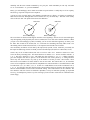
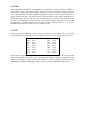
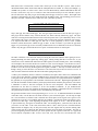
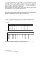
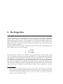
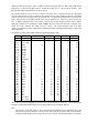
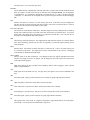
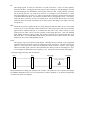
The floppy user guide
Michael Haardt ([email protected])
Alain Knaff ([email protected])
David C. Niemi ([email protected])
ABSTRACT
This document1 is intended for people interested in details about floppy drives, e.g. the interface bus, data recording, logical structure of data on the floppy and more. The connection to Linux is made where applicable to show how floppies from other computers can
be accessed or how and why it is possible to put more data on a floppy. Since they use
the same interface, there is also a small section about floppy tape streamers.
June 11th, 2001
1.
The unmodified version of this document may be distributed without charge, both as roff source or as formatted or printed
manual.
1. Floppy drive sizes
Inside the case is the floppy disk, a round plastic foil coated with a material containing metal oxide, which
can be magnetised to store information. The case has multiple openings. The bigger hole in the middle
allows the drive motor to spin the floppy clockwise.
Old floppy drives use a DC-motor with a variable resistor to adjust the speed. They often have a
stroboscope ring on their bottom for that purpose. Modern drives have brushless motors. The big disk on
the bottom contains permanent magnets and is controlled by an SIL-IC with a heat pipe and connections to
coils under the disk. This unit is controlled with a crystal or ceramics resonator. If you want to change the
drive speed, adjusting the variable resistor works for older drives, but not for newer ones. On those, you
will need to change the crystal. The speed may off by at most 2%.
The longish hole is used for the drive read/write head to touch the disk. The smallest hole in the case is for
detecting the index hole. An LED/optical element gives a signal when the index hole appears. The writeprotect notches are sensed using micro switches.
There are one sided and two sided floppy disk drives, depending on if they only have a head on bottom or
also on top. Floppies are available as both one or two sided, but here one sided only means that only side 0
is verified by the manufacturer. You may use side 1 at your own risk. At today’s prices that should not be
an issue any more, though.
When transporting floppy drives, the read/write heads should be protected from touching each other with a
piece of cardboard like shown below. Usually those come with the drive when you buy it, but if you didn’t
get one, then you can copy the given pictures on thin cardboard and cut them out. If nothing else, you
should at least insert an old floppy in the drive. The drive door should be locked. Make sure to remove the
cardboard from the drive before switching it on again.
1.1 8" drives
This is the oldest format, they are just called floppy disks. It is rarely used these days. 8" floppies rotate
with a speed of 360 RPM. It is common for these drives to need +24V, 1.8A and +5V, 1.3A as well as
110/230V, the latter being used for synchronisation. To switch between 50 and 60 Hz, you have to turn the
wheel which drives the belt around, to change the used radius. Many drives support both hard and soft
sectored floppies, selectable with a jumper. For certain drives, you have to install an upgrade kit for hard
sectored floppies.
1.2 51⁄4" drives
This format appeared under the name mini floppy disks. They were intended as replacement for 8" disks,
so you can replace an 8" soft sectored drive with a 51⁄4" drive (if you only want to continue running the
machine). The other way round, you can connect soft sectored 8" drives to floppy disk controllers which
are intended for 51⁄4" floppies. DD drives rotate with a speed of 300 RPM, HD drives at 360 RPM. If a HD
drive accesses a DD floppy, it either switches to 300 RPM (dual speed drive) or the controller works with a
data rate of 300 kBit/s instead of 250 kBit/s, like most PCs do.
1.3 3" drives
Amstrad used 3" floppies in the CPC and PCW series. Nobody else did, so this format has disappeared.
The floppy case was more robust than the 31⁄2" case is, which caused it to be about two times as thick. Also
similar to 31⁄2" floppies, they have a slider which protects the floppy disk and only opens inside the drive to
let the read/write head touch the disk.
1.4 31⁄2" drives
This is the standard format these days, usually called micro floppy disks. The floppies rotate with with 300
RPM. The Macintosh DD floppies make an exception as they have a variable speed, rotating from 300–600
RPM.
In fact 31⁄2" floppies should be called 90-mm-floppies, as they were introduced as such in Japan, where
people use metrical units, but 31⁄2" are almost 90 mm and everybody knows them by this name these days.
Further the following standards describing them show the true name:
ISO type 301 = 90 mm, DD
ISO type 302 = 90 mm, HD
ISO type 303 = 90 mm, ED
The 31⁄2" disks have no index hole but a small square mark.
2. Floppy geometry
Most floppies which are in use today store data on tracks which are organized as concentric circles. Those
tracks are further divided into sectors (see below). Tracks are accessed by moving the disk drive heads.
Tracks are counted beginning with 0, with track 0 always being the most outside track on side 0. Tracks
which are vertically over each other (e.g. track 0 and the track which is located right under track 0 on the
other side) are called a cylinder. Tracks may be counted either using flip sides, that is cylinder 0 containing
track 0 and track 1, or up and over with cylinder 0 containing track 0 and track 159 (for 80 cylinder
formats). 8" drives usually support 77 cylinders. 51⁄4" drives usually support either 35 (old and rare), 40, 77
(also old and rare) or 80 cylinders. 31⁄2" drives usually support 80 cylinders. 3" drives are available with 40
or 80 cylinders.
Those are manufacturer specifications. Experience has shown that many drives support a little more.
Trying once if a drive does will probably not damage it (no warranty on that though). But if the drive
makes odd mechanical noises or you get errors, then stop immediately or the drive may get physically
damaged. A track on a 31⁄2" disk is about 0.19 mm wide, so the mechanics has to be very exact and it is
quite sensible.
As a matter of fact, the tracks of a cylinder are not exactly over each other, but spatially interleaved. For
that reason you can not read a floppy which was written in a dual head drive by flipping it in a single head
drive (even if you could reverse the spin direction). At least 8" diskettes have that much room between
tracks, that you can flip a double sided floppy around and use it twice that way. There may be a few bad
sectors, but you can put 2.4 MB on one floppy that way. This does not work with a 51⁄4" floppy, though.
You can use its first track, but that is it.
Drives which only support 40 cylinders have wider tracks and wider read/write heads. This can cause
problems when files should be transported from a 80 cylinder drive to a 40 cylinder drive, because the
wider head will get a signal mixture of two tracks. Formatting the floppy first with 80 and then with 40
cylinders on the 80 cylinder drive usually solves any problems.
The Commodore 1541 drive uses zone bit recording. The drives have 35 tracks and four zones. The disk
speed stays the same in all zones, but the length of a bit cell is switched between the zones using a
monoflop with the time constant controlled by two port pins. With 300 RPM you can only read track
18–35. To read track 1–17, you need 280 RPM.
Rarely, you will find floppy drives which record data in a spiral scheme. Usually they are of low capacity
and used e.g. in special word processor computers.
A sector is a part of a track and it is the smallest accessable unit of a floppy. 8" floppies are available as
hard and soft sectored, although hard sectored formats are very rare these days. The term sector usually
refers to the user data. The picture below shows the difference:
Index hole
Soft sectored floppy
Index hole
Hard sectored floppy
The sector holes for hard sectored floppies mark the sector beginnings, whereas for soft sectored floppies
only the beginning of the physically first sector is marked, the rest is done with controller hardware. When
you spin a soft sectored floppy by hand, eventually you can see the index hole appearing. In theory even
the index hole would not be needed, but it is convenient for formatting and many FDCs need it for
determining when a normal read/write fails, i.e. the requested sector header was not found.
You can identify each block of user data by the triple (head, cylinder, sector). With PCs you usually use
that triple for addressing, whereas on CP/M you often used the triple (track, how to count tracks, sector).
Sectors may not be recorded ordered, but with a interleave and a skew. Interleave means not to store
sectors in directly ascending order. The neutral interleave is called 0 or 1:1. Sectors would be ordered 1, 2,
3, 4, 5. The next is interleave 1 or 2:1, with which the order would be 1, 4, 2, 5, 3. A higher interleave
gives the computer more time to process a sector before the next sectors passes by. A wrong interleave
factor may slow down accesses very bad, up to the number of sectors per track. Skew means a skew
between the sector numbers of tracks which are next to each other. The neutral skew is 0, for which the
sectors of two neighbour tracks (note that for simplification a neutral interleave is assumed further) would
be ordered like 1, 2, 3, 4, 5 and 1, 2, 3, 4, 5. A skew of 1 would shift the sectors of the second track to be 5,
1, 2, 3, 4. A wrong skew can slow down accesses at most with the factor two, because once the first sector
has been found all further sectors can be read without waiting. Skew and interleave can be combined. The
best interleave and skew factors are hardware dependent, so keep in mind that speeding up sequential
access e.g. for backups may lead to very slow restoring if you are forced to restore files on a machine with a
slower floppy.
3. Data recording
The data transfer between floppy controller and floppy drive is serial, which is why it is measured in either
bit per second or Hz. The transfer rate is specified by the floppy type and the drive. XT controllers use 250
kBit/s, AT controllers can use 250 kBit/s, 300 kBit/s or 500 kBit/s. Of course higher bit rates not only
mean a faster data transfer rate, they also influence how much fits on a track. For example, a floppy
rotating at 300 RPM can record 6250 byte at 250000 bits per second. Newer AT controllers can use up to 1
MBit/s, which is used for 31⁄2" ED drives and which also speeds up streamers connected to the floppy bus.
You can not speed up usual floppy drives by using 1 MBit/s data rate, though. Usual floppy drives record
data by magnetising the floppy disk parallel to the surface. 31⁄2" ED drives magnetise them perpendicular
for ED formats to the surface to achieve a higher density.
Floppies do not always spin with exactly the same speed, so besides the data signal the clock signal needs
to be recorded. There are various ways to do that, which will be shown in the following sections.
3.1 FM
FM (frequency modulation) is also called SD (single density). The data is divided into bit cells. At the
beginning of each cell, a clock signal is recorded. After half the width of the bit cell, the data bit is
recorded. This is the byte 0x59 in FM:
0
1
0
1
1
0
0
1
Each bit cell is 4υs long (at 250 kHz). As you can see, a 0 bit is needed to be able to synchronize clock
detection. That is the reason why data must be preceeded by special signal sequences, to synchronize a
monoflop or PLL and to find out when a sector or data starts. Although the 765 has the capability to work
in FM, it is not implemented on most PC FDCs. Some older controller boards can be modified to read FM
disks quite easy by connecting the inverted FM/MFM signal from the 765 with the appropiate line on the
separator. If you want to write FM disks, you need schematics of the controller and a more sophisticated
approach is needed. Sydex’ shareware DOS program 22DISK, which reads many CP/M disk formats,
explains this more detailed. The table below lists the results from a test made by Don Maslin
<[email protected]>. He used a 80286 with each of the controllers to create a copy of an Osborne 1 system
disk on a 360k drive. If the creation seemed successful, then it was read using the same controller. A
marginal test result means that the controllers produced a satisfactory SSSD Ozzie disk, but with so much
reseeking of tracks, and spurious error signals that they cannot be considered satisfactory.
Successful
Drives
Chip
2 FD
8473
4 FD
8473
2 FD
Acer M5105
2 FD
8473
2 FD
8473
2 FD
WD37C65AJM
4 FD
WD37C65BJM
2 FD
WD37C65BJM
Marginal
2 FD
8973
4 FD
82077SL
2 FD
8973
Failure
3/4 length XT card
4 FD
UM8398
Name
DTK Mini/Micro-2
DTK Mini/Micro-2
MID-400KF
Seagate ST-12
Seagate ST-22
WD1002A-FOX
WD1002A-FOX
WD1006V-SR2
DTK Mini/Micro-2
GSI Model 11
LCS-6610F
IBM 4 FD NEC765AC
SUNIX-4310
Remarks
Multi I/O
H/FDC
H/FDC
H/FDC
UMC chip
3.2 MFM
FM needs much time to record the clock signal for each data bit. That is why MFM (Modified Frequency
Modulation) was invented. It allows the recording of double the density compared to FM without
increasing the bit rate on the floppy material. Any MFM capable drive should be able to be used with FM,
but not vice versa. Each bit cell has only half the size compared to FM. If a cell contains a 1, the signal
will be recorded in the middle of the cell. If a cell contains a 0, the signal will be recorded at the beginning
of the cell, unless it was preceeded by a cell with a 1. If a signal is transmitted for a 0 cell, it is used as
clock signal. Again the byte 0x59, now in MFM:
0
1
0
1
1
0
0
1
All PC floppy drives use MFM, as do older hard disks and floppy tape streamers. The 765 used in PC
FDCs is not capable to read 128 byte sectors in MFM, a format often used by Altos.
3.3 M2FM
Beside MFM, there is also M2FM. As with MFM, a cell containing a 1 will have a signal in its middle. A
cell containing a 0 only will contain a signal if the previous cell does not contain a signal. This causes
signals to have a bigger average distance which reduces the need for precompensation. Signals which are
closer to each other than to their other neighbour signals have a tendency to move away from each other on
a floppy for physical reasons. This problem is more serious for the inner tracks, because obviously there is
a higher data density. To reduce this effect, they are written about 150 ns closer to each other than usually
(the time is drive dependent), so when they move a little they are just at the right position. This is called
precompensation. Standard controllers do not support M2FM recording because it is a lot more
complicated to read data back, which is why it is rarely used today.
3.4 GCR
GCR (Group Code Recording) uses a table to map 4 bit of data into 5 bits of signals. This code is chosen
in a way that there are never more than two zero signals after another. That is how the clock is generated:
data
0000
0001
0010
0011
0100
0101
0110
0111
recording
11001
11011
10010
10011
11101
10101
10110
10111
data
1000
1001
1010
1011
1100
1101
1110
1111
recording
11010
01001
01010
01011
11110
01101
01110
01111
GCR is used by Apple II and Commodore CBM/C64/C128 computers, which is why those floppies would
need a special controller to be read in a PC. Although Linux should be capable of reading most CP/M
formats, CP/M running on a Apple with Z80 card would be an exception. Macintosh computers use GCR
on DD floppies and MFM on HD floppies, which is why you can only read HD Mac floppies on a PC.
4. Track and sector structure
This section documents which information is stored in a track and a sector. Getting this information on to
the disk is done during formatting. It is needed to be able to store user data in sectors or load user data
from them. When you read data from a raw floppy device under Linux you will only read the user data.
Sometimes you may get error messages though, like when reading defect or unformatted disks. You will be
able to understand their true meaning when looking them up in this section. This documents both FM and
MFM, because there are only minor differences. x/y means: x for FM and y for MFM. Italic numbers mean
that the number is subject to change for different disk formats. The actual numbers shown document the
IBM 3740/IBM 34 format.
40/80 byte filled with 0xff or 0x00/0x4e
6/12 byte filled with 0x00
0/3 byte 0xc2
This is the structure of the pre-index gap. It starts right after the first edge of the index hole signal. It
allows the floppy controller to detect the start after the index hole. The pattern 0xc2 is only used for MFM
and has a missing clock transition between bit 3 and 4 which is used to synchronize the controller logic.
1 byte index mark 0xfc
This is the index mark. For FM, it is written with a clock byte of 0xd7.
26/50 byte 0xff or 0x00/0x4e
6/12 byte 0x00
0/3 byte filled with 0xa1
Gap 1 (post index gap). The bytes 0xa1 have a missing clock transition between bit 4 and 5 and preset
CRC. The NEC 765 controller goes to sleep for about 1.8ms after the index hole is sensed and expects still
to read gap 1 when it wakes up. It works fine for floppies formatted using the 765, because it will always
generate the format as specified above. The WD 1797 controller, though, does not have a command to
format a track, but writes a given pattern to the track when formatting it. If the pattern has a too short post
index gap, for example because it is a format which tries to maximise the usable disk space, the 765
controller will fail to read the first sector. To make things yet more complicated, the 765A controller only
sleeps for 0.6ms, which means it is less sensitive to shorter post index gaps.
1 byte ID address mark 0xfe
1 byte Cylinder number
1 byte Side number
1 byte Sector number
1 byte Sector length
2 bytes CRC
ID record. This starts the sector. For FM, 0xfe is written with a clock byte of 0xc7 and also presets CRC.
Cylinder and side number are counted starting with 0. The sector number is counted starting with 1.
Sometimes other start values are used, which results in a simple copy protection. The sector length field
contains log2(length of user data field)−7.
There have been some CP/M computers which use one-sector floppies where the sector length is not 128
muliplied with a power of 2. The 1797 controllers allows such formats, the 765 controller does not.
For an explanation of the CRC see below.
11/22 byte filled with 0xff or 0x00/0x4e
6/12 byte filled with 0x00
0/3 byte filled with 0xa1
Gap 2 (ID gap). The write gate signal turns active with the beginning of the 6/12 bytes containing 0x00.
For MFM, the bytes 0xa1 have a missing clock transition between bit 4 and 5 and preset CRC (cyclic
redundancy check). When overwriting a sector, the FDC first looks for the right header. During this
process, the erase head is not yet switched on. As soon as the right header is recongnized, the erase head is
switched on, and the read/write head is toggled to writing. However, because of the spatial distance
separating both heads, the erase head cannot erase right after the header, but rather has to skip a gap. ED
drives need twice as big gaps because they record data with twice the density on the same space. HD drives
do not need twice as big gaps compared to DD drives, because they have a smaller spatial distance between
the erase and the read/write coils in the head. It was physically not possible to do this once more for ED
drives, though.
1 byte data address mark 0xfb
User data
2 bytes CRC
Data field record. For FM, 0xfb is written with a clock byte of 0xc7 and CRC is preset. There is also a
deleted data address mark, which means that the subsequent data are invalid. It is rarely used though, e.g.
on IBM 3740 systems. Its value is 0xf8. Since even user data headed by a deleted data address mark can
be read, it is not safe to rely on it. For FM, it is also written with a clock byte of 0xc7 and CRC is preset.
The user data is the only data you get when reading from a floppy raw device in Linux. The length of the
user data is determined by the sector length field in the ID address mark. The formatting process writes a
fill byte as user data. CP/M uses 0xe5, Linux uses 0xf6. [And other systems?]
27/54 byte filled with 0xff or 0x00/0x4e
6/12 byte 0x00
0/3 byte filled with 0xa1
Gap 3 (data gap, also called format gap). The write gate signal turns inactive after the first byte of gap 3.
This gap is the last element of any sector but the last one, which is directly followed by gap 4. The bytes
0xa1 have a missing clock transition between bit 4 and 5 and preset CRC (cyclic redundancy check). It was
observed that with a gap 3 from 0x20 to 0x30 the time to read a track increases continuesly (not in steps).
It is suspected that with too small gaps, the FDC has a certain propability to miss a sector (without
interleave) which increases the smaller the gap is made. It does not matter if you make the gap much
bigger or if you increase gap 4, but it is usually considered more nice to distribute sectors all over the disk,
which is why this gap is used to fill the left over space on formats with lots of wasted space.
274/652 byte filled with 0xff or 0x00/0x4e
The FDC will fill the rest of the track with bytes having the value 0x4e until the index signal gets active.
During formatting, the index signal stops writing gap 4. During writing data this is not the case, so you
could write a sector which header ends before the index signal, but its data extends past it. Since formatting
was incomplete, this sector first needs to be written or a CRC error will happen. You still have to leave a
margin of at least 35 bytes before the 12 bytes containing 0x0. If you don’t leave that margin you may still
be able to access the sector by flickering the motor signal (‘‘twaddle’’). This may not work with all drives
though. Doing so causes the drive to be deselected. The motor line only needs to be off for a few ms. It
does not matter if that time matches the time of the index signal getting active!
A CRC (cyclic redundancy check) is similar to a checksum, but requires more efforts in its calculation and
is more safe in error detection. Instead of adding all bytes, the bit stream with as many zero bits appended
as the grade of the used test polynomial, is used as coefficient matrix for a polynomial which is divided by
the generator (or test) polynomial. The remainder of the division is the CRC. Replacing the appended zero
bits with the remainder coefficient matrix yields a polynomial which, divided by the generator, will result in
a remainder 0—unless it has been corrupted, at least for most corruptions. Note that addition and
substraction are the same as exclusive or in the used modulo-2 arithmetic. If you understand the
replacement of zero bits by the remainder as subtracting the remainder, it should become obvious that this
new polynomial will cause a remainder of zero when divided by the generator.
The generator used here is the CCITT polynomial g(x)=1+x5+x12+x16. To understand hardware calculation
of the CRC value, view the data as a bit stream fed into a cyclic 16 bit shift register. At each step, the input
bit is xor’ed with bit 15, and this result is fed back into various places of the register. Bit 5 gets bit 4 xor
feedback, bit 12 gets bit 11 xor feedback and bit 0 gets feedback. All other bits simply get rotated e.g. bit 1
gets bit 0 on a clock edge. At the beginning, all flip flops of the register are set to 1. After the last data bit
is processed that way, the register it contains the CRC. For checking CRCs, you do the same, but the last
you feed to it is the CRC. If all is fine, then all bits will be 0 after. Since bytes are recorded with their
highest bit first on floppies, they are also processed by the CRC register that way and the resulting CRC
will be written with bit 15 being the first and bit 0 being the last to the floppy (big endian). The CRC is
processed beginning with the first 0xa1 byte which presets the CRC register, so the CRC of a typical ID
record would be computed as CRC of 0xa1, 0xa1, 0xa1, 0xfe, 0x0, 0x0, 0x3, 0x2 and have the value
0xac0d. 0xac will be the first CRC byte and 0x0d the second.
The ECMA/ISO format, as used by the controllers 7265 and 745, does not use the pre-index gap, index
mark and gap 4. These controllers can read IBM compatible floppies, but not vice versa.
5. Drive constants
There are a couple drive dependent time constants. Today you usually don’t get a manual when buying a
floppy drive, but fortunately there are values which may not work best for your drive, but at least they work
safe.
The step rate is the time between two steps when the head moves over the disk. The traditional value for
PC drives is 8 ms. 51⁄4 HD drives usually work with 6 ms, and 31⁄2 drives are usually used with 3 ms. A too
big step rate will work, but cause unpleasant noise, and also stresses the drive mechanics. This is caused by
the step motor having an optimal frequency where it just spins smooth while making a few steps. Usually
too big or too small values cause the drive to sound odd, whereas the ‘right’ value causes it to work very
silent. At too small values you may also get positioning errors.
After the head changes between tracks it must be given the head settle time before any further action.
Older drives needed 25 ms, newer ones often only need 15 ms for head vibrations to disappear.
The motor startup time is needed by the motor to reach the needed speed. A typical value is 1 sec. Often
half the value is used when reading floppies because read errors can be corrected by making a new try.
The head load time is the time a drive needs to move the heads on the disk surface. Since with PCs the
heads are loaded when the motor speeds up, the head load time is not important because the motor startup
time is much longer and it will be waited that much anyway. A typical head load time value is 4 ms.
There is also a head unload time. A typical value is 480 ms.
After a floppy access is done, the motor will be kept spinning for the [what’s the name of it?] time. In case
the next access is done very soon, this avoids again having to start the motor. It improves access latency
time and stresses the mechanics less. A typical value is 1.8 sec.
[What is the write current off time?]
To adjust drives mechanically, you need an alignment disk, which contains tracks that look like this:
To adjust head radial position, the head position should be adjusted for equal amplitude of the two signals.
The index pulse position is supposed to be set within a fixed time (e.g. 50υs) referring to a pulse on the
disk.
The head azimuth is supposed to be ±12–18 minutes. Since it is not field-adjustable, you will have to
exchange the head assembly if it is out of tolerance.
Note: Alignment disks can not be produced using regular floppy drives, you will have to buy them and they
are not cheap. Only use them for alignment purposes, not to check out broken floppy drives. First a drive
should be able to read floppies it wrote, then you can align it.
6. Using non-standard formats
If you get a floppy and don’t know anything about it, first try to read a block of 128 bytes from it. This is
done with the disk dump program, dd(1).
$ dd if=/dev/fd0 of=/tmp/foo count=1 bs=128
1+0 records in
1+0 records out
In case this works, Linux has (probably) correctly auto-detected the floppy format. You can print the
format specification using:
$ getfdprm /dev/fd0
2400 15 2 80 0 0x1b 0x00 0xdf 0x54
If dd fails or if getfdprm2 prints ‘No such device’ then the format is most likely not in the autodetection
format list. For example, this list does not include FM formats. If this happens or if you know that the
floppy you want to identify does not contain a format commonly used on PCs, you will have to set the
format by hand with setfdprm. If the floppy in question has been written by a CP/M machine, the
shareware DOS program 22DISK and ANADISK3 from Sydex may be helpful.
The parameters printed by getfdprm and set using setfdprm mean the following:
2400 is the number of sectors on the disk.
15 is the number of sectors per track.
2 is the number of heads (1 means single sided).
80 is the number of cylinders.
2.
getfdprm and related programs can be obtained via ftp from ftp.imag.fr:pub/Linux/ZLIBC/fdutils
3.
22DISK is stored in a file called 22dsk142.zip and ANADISK is stored as anad207.zip. A search engine like archie should find
the nearest site which stores them.
0 is a stretch factor which specifies how many additional steps have to be made when moving from one
cylinder to the next. If bit 0 is 0, then only one step is made, if it is 1 then two steps per track are made.
This is needed to access a floppy formatted with 40 cylinders in an 80 cylinder drive, because one 40
cylinder track is just as wide as two 80 cylinder tracks. If bit 14 is set, then the head numbers will be
exchanged: Head 0 becomes head 1 and head 1 becomes head 0.
0x1b is a gap parameter, which meaning is unknown. It must be passed to a PC floppy controller with read
and write commands, but no effect of modifying it has been observed yet.
0x00 is a code for the bitrate/recording frequency used: 0x00 means 500 kHz, 0x01 means 300 kHz, 0x02
means 250 kHz and 0x03 means 1 MHz (but perpendicular mode must be chosen in addition to 0x03 in
order to generate the correct gaps). If the highest bit is cleared, MFM will be used, otherwise FM. FM
currently does not work on Linux, it is unknown if this is due to hardware or software problems. Using FM
means that only half the frequency will be used, so 0x82 means FM with 125 kHz.
0xdf is a special byte specifying the stepping rate in the upper nibble, where f means 1 ms, e means 2 ms,
and so on. d, as shown here, means 3 ms. The lower nibble specifies the head unload time: 1 means 16 ms,
2 means 32 ms and so on. f, as shown here, means 240 ms.
0x54 is the format/data gap 3.
Note: Many CP/M formats use a different format on track 0, e.g. FM on track 0 and MFM otherwise.
The following tables should help you to identify formats and systems.
51⁄4" SD drives:
Name
CP/M
CP/M
CP/M
CP/M
CP/M
CP/M
Rec.
FM
FM
FM
FM
FM
FM
kHz
125
125
125
125
125
125
Cyl.
?
?
?
?
?
?
Sides
?
?
?
?
?
?
Sect.
18
16
8
4
2
1
Length
128
128
256
512
1024
2048
Gap 3
0x09
0x19
0x30
0x87
0xff
0xff
Gap ?
51⁄4" DD drives:
Name
CP/M
CP/M
CP/M
CP/M
CP/M
CP/M
PC-XT
CBM-1581
Rec.
MFM
MFM
MFM
MFM
MFM
MFM
MFM
MFM
kHz
250
250
250
250
250
250
250
250
Cyl.
?
?
?
?
?
?
40
80
Sides
?
?
?
?
?
?
2
2
Sect.
18
16
8
4
2
1
9
10
Length
256
256
512
1024
2048
4096
512
512
Gap 3
0x0c
0x32
0x50
0xf0
0xff
0xff
0x50
0x2e
The CBM-1581 format has reversed sides, so bit 1 of the stretch byte must be 1.
51⁄4" HD drives:
4.
Bit is only processed in Linux 1.3.4 and upwards.
Gap ?
0x2a
0x2a
Name
?
?
?
PC-AT
Rec.
MFM
MFM
MFM
MFM
kHz
300
300
300
500
Cyl.
40
80
83
80
Sides
2
2
2
2
Sect.
9
9
10
15
Length
512
512
512
512
Gap 3
0x50
0x50
0x30
0x54
Gap ?
0x23
0x23
0x25
0x1b
Rec.
MFM
MFM
kHz
250
250
Cyl.
40
80
Sides
2
2
Sect.
9
9
Length
512
512
Gap 3
0x50
0x50
Gap ?
0x2a
0x2a
Rec.
MFM
MFM
MFM
kHz
250
500
500
Cyl.
80
80
80
Sides
2
2
2
Sect.
9
18
21
Length
512
512
512
Gap 3
0x50
0x6c
0x6c
Gap ?
0x2a
0x1b
0x0c
Rec.
FM
FM
FM
FM
FM
FM
kHz
250
250
250
250
250
250
Cyl.
?
?
?
?
?
?
Sides
?
?
?
?
?
?
Sect.
26
15
8
4
2
1
Length
128
256
512
1024
2048
4096
Gap 3
0x1b
0x2a
0x3a
0x8a
0xff
0xff
Gap ?
31⁄2" DD drives:
Name
?
?
31⁄2" HD drives:
Name
?
?
?
8" SD drives:
Name
CP/M
CP/M
CP/M
CP/M
CP/M
CP/M
8" DD drives:
Name
Rec.
kHz
Cyl.
Sides
Sect.
Length
Gap 3
Gap ?
CP/M
MFM
500
?
?
26
256
0x36
CP/M
MFM
500
?
?
15
512
0x54
CP/M
MFM
500
?
?
8
1024
0x74
CP/M
MFM
500
?
?
4
2048
0xff
CP/M
MFM
500
?
?
2
4096
0xff
CP/M
MFM
500
?
?
1
8192
0xff
Once you can physically read the floppy, e.g. using dd, the next question is how to get stored files back.
The following list of archive formats and file systems along with software to deal with them may help you:
•
tar. Tar is the tape archiver and if you have a Linux system, it should already contain tar. If not, then
look on your nearest GNU mirror.
•
ar. Ar, the old standard UNIX archiver is also a standard command. Unfortunately, there are two
incompatible flavours.
•
MSDOS. If you compiled the MSDOS file system (and loaded it, if it is a module), you can directly
mount floppies under Linux. Alternatively, you can use the mtools package, which has the advantage
that you do not have to mount/umount file systems each time. Old 360k floppies may require to edit
their boot sector, if it is empty.
•
CP/M. If you want to access CP/M file systems, best make an image of the disk first. The CP/M file
system characteristic sizes are not stored on the file system, so you may take a few tries until you got
them right. Cpmtools are available from http://www.moria.de/˜michael/cpmtools/.
7. Floppy tape streamer sizes
Floppy streamers use the same interface floppies do, hence the name. They also use MFM recording, but
the meaning of some control lines is different. All capacities given below are uncompressed. The
following standards exist:
QIC-80
28 tracks on 1⁄4" tape with 550 Oe magnetic material, resulting in 80 MByte (205 ft, DC2000/2080
tape), 120 MByte (307.5 ft DC2120 tape) or 172 MByte (425 ft DC2120XL tape) or 400 MByte
(1000 ft tape). A data rate of 500 kBit/sec or 1 MBit/sec is used. The data density is 14700 Bit/inch
(bpi).
QIC-80 WIDE/TR-1
36 tracks on 8 mm tape with 550 Oe magnetic material, resulting in 200 Mb (400 ft, MC3000XL???
tape), 400 MByte (750 ft tape) or 500 MByte (1000 ft tape). This is essentially QIC-80, but with a
wide tape (hence the name). A data rate of 500 kBit/sec or 1 MBit/sec is used. The data density is
14700 Bit/inch (bpi).
QIC-3010
40 tracks on 1⁄4" tape with 900 Oe material, resulting in 340 MByte (400 ft tape) or 800 MByte (1000
ft tape). A data rate of 500 kBit/sec or 1 MBit/sec is used. The data density is 22125 Bit/inch (bpi).
A QIC-3010 drive can read a QIC-80 tape, but not write to it.
QIC-3010 WIDE/TR-2
It uses 50 tracks on 8 mm tape with 900 Oe material. This gives 425 MByte (400 ft), 800 MByte
(750 ft tape) or 1100 MByte (1000 ft tape). A data rate of 500 kBit/sec or 1 MBit/sec is used. The
data density is 22125 Byte/inch (bpi).
QIC-3020
40 tracks on 1⁄4" tape with 900 Oe material, resulting in 680 MByte (400 ft tape) or 1700 MByte
(1000 ft tape). This is a kind of double-density QIC-3010: A data rate of 1 MBit/sec or 2 MBit/sec
and a double data density of 44250 bpi is used. The 2 MBit/sec data rate requires a special FDC
(82078-1 or similar), like found on the FC-20. QIC-3020 drives can read and write QIC-3010 tapes
and read QIC-80 tapes.
QIC-3020 WIDE/TR-3
It uses 50 tracks on 8 mm tape with 900 Oe material. This gives 833 MByte (400 ft tape) or 1600
MByte (750 ft tape). This is a kind of double-density QIC-3010 WIDE: A data rate of 1 MBit/sec or
2 MBit/sec and a data density of 44250 bpi is used. The 2 MBit/sec data rate requires a special FDC
(82078-1 or similar), like found on the FC-20.
8. The Floppy Bus
Shugart and Associates 5 were so successful in the business of floppy drives, that the bus they developed
became a de facto standard. The Shugart bus is a special purpose bus which connects a floppy disk
controller (FDC) with up to four drives. The PC floppy bus is very similar to the shugart bus which is why
both are described here. In contrary to the shugart bus, it can only be used for up to two floppy drives.
IBM’s PS/2 series has yet another bus, which, for instance, also supplies the drives with power. [I wish I
had more information on that bus.]
The power connector consists of a AMP 1-480426-0 or equivalent on the drive and a AMP 1-480424-0 with
60619-1 female contacts. Power is connected as:
1
2
3
4
12 V DC
12 V DC return
5 V DC return
5 V DC
The signal connector consists of a 34 conductor card edge signal connector on the drive and a AMP
583717-5 or equivalent on the cable. The signal cable should be a 34 conductor AWG #28 ribbon cable
with a minimum of two and a maximum of five connectors for daisy chain installation. The cable must not
be longer than 6 feet. The older approach is a line termination with 150R ± 5% to 5 V DC. Those resistors
have a DIP case, looking similar to a chip, but with a white surface. One of the drives connected to the
daisy cable shall terminate all of the signal lines from controller to drive except for the select lines. Each
select line will be terminated by the drive being addressed by it; unused select lines are not terminated.
Signal lines from drive to controller are terminated by the controller. The newer approach is to use 10K
5.
Shugart and Associates were originally sold to Xerox in the late 1970’s/early 1980’s. Alan Shugart signed a non-competition
agreement, by which he agreed not to start another disk drive company for at least two years. Xerox, though, could not keep the
Shugart company the same successful company that it had been. It lost money and finally went out of business. After that time
he started a new company, Shugart Technology, but Xerox gave him a lot of trouble, so he changed the name to Seagate
Technology. Today, he is still the CEO of Seagate.
pull-up resistors on each drive. There is further a scheme for mixing older 51⁄4" drives with 220R resistor
packs with 31⁄2" drives having 4K7 resistors. Furthermore, there are 31⁄2" drives with 1K resistors. Note
that 10K and 150R terminated drives can not be mixed.
The signal levels are 0 to 0.8 V DC for a 0 and 2 to 5.25 V DC for a 1, signals are active low. The signal
driver in a drive shall be a 7438 or equivalent, the signal receiver in a drive shall be a 74LS14 or equivalent
with the maximum of one signal receiver per line per drive. All pins having odd numbers are connected to
GND. All pins with even numbers which do not carry a signal are NC. There are 8" drives which may
have a slightly different pinout. The FTAPE connector for external floppy streamers uses a DB-37
connector, with pins 20–37 connected to GND. POW[1–4] refer to the power connector on the tape drive,
which is a ‘‘mini’’ connector like found on most 31⁄2" drives. The 37-pin connector refers to the cable
which gets plugged an interface which has the standard PC floppy bus and an standard power supply plug
on the other side.
The pinout is given in a form which should ease producing adapter cables
from
Drive
Drive
Drive
Drive
+5 V
GND
GND
+12 V
FDC
FDC
FDC
Drive
FDC
FDC
FDC
FDC
FDC
FDC
FDC
FDC
FDC
FDC
FDC
Drive
Drive
Drive
FDC
Drive
Drive
Drive
signal
True ready
Two sided
RDY
Sector
POW4
POW3
POW2
POW1
LSD
DENSEL
INU
IDX
DS1
MOT1
DS2
DS3
DS4
MOT
MOT2
DIR
STP
WD
WG
TK0
WP
RD
SS
DC
Sep. Data
Sep. Clock
Amstrad 8xxx 26
pin
Shugart 34
pin
PC 34
pin
FTAPE 37
pin
26
1
2
3
4
5
2
4
6
8
10
12
14
16
18
20
22
24
2
4
8
10
12
14
6
16
18
20
22
24
26
28
30
32
34
2
8
14
10
12
6
9
7
8
16
18
20
22
24
26
28
30
32
34
10
11
12
13
14
15
16
17
18
19
Shugart 50
pin
8
10
22
24
18
2
16
20
26
28
30
32
34
36
38
40
42
44
46
14
12
48
50
Pin 24, 48, and 50 of the Shughart 50 connectors are used for hard sector drives only. [The FTAPE pinout
should be checked for mistakes and the correct signal names for tapes should be added!]
LSD
put the heads on the disk. Most 8" drives have their heads unloaded except when being active, but
their motors often run continuosly. If a drive needs this signal, then it can be connected to the Motor
on signal, which should get active before the drive gets selected. The head load signal is sent before
selecting a drive. It is not used by tape drives.
DENSEL
selects double density or high density and at the same time if reduced write current should be used as
those are coupled. For this reason, this pin is sometimes also called low current. [Level assignment
is still unknown. It is said that the assignment is inverted between 51⁄4" and 31⁄2" floppies.] Modern
‘‘intelligent’’ 31⁄2" HD drives do not depend on this signal but recognize the data rate from the floppy
disk.
INU
Tells the drive that it is used now. It is not used by tape drives. Some drives may be configured to
turn their motors on based on the IN USE LED, which in turn can be set when the drive is selected.
That way, the drive does not need a MOT or INU signal.
DS1, DS2, DS3, DS4
Select the first, second third or fourth drive. With PCs, floppies are always jumpered as second drive
and the select and motor lines are twisted in the cable between the two possible drives. If you have
trouble with a new floppy drive, first check if it is jumpered as second drive. Note: On some drives,
the jumpers are labelled DS0, DS1, DS2 and DS3.
IDX
Generated by index hole detection. This signal initiates and terminates transfer of controller data to
drive when formatting, generated by the drive at beginning of each track/segment during read or
write operations.
MOT
Start the motor. This is done no matter if the drive is selected or not. 8" drive AC motors always run.
It is not used by tape drives. This signal can be used to load the heads of an 8" drives, if the floppy
controller has no dedicated head load signal.
MOT1, MOT2
Start the motor of the first/second drive. The Shugart bus does not support individual motor lines
which is why floppy drives have no jumper. The PC floppy bus does, but requires the twisted wires
in the cable for that purpose.
DIR
High when stepping to outer cylinders (lower numbers) and low when stepping to inner cylinders
(higher cylinder numbers).
STP
Each signal moves the heads one step. For tape drives, this signal is used to send commands to the
drive.
WD
Serial data signal, a pulse per flux transition to be recorded, low going edge indicates transition.
WG
High when data is read and low when data is written to the drive.
TK0
Track 0 detection. Tape drives use this to transfer drive status to the controller.
WP
Inserted floppy is write protected. Tape drives use this to transfer drive status to the controller.
RD
Serial data signal, a pulse per flux transition, low going edge indicates transition.
SS
This signal selects a drive head. It is high for using head 0 (upper head) and low for using head 1
(lower head). It is also used to send commands to tape drives.
DC
Disk change signal. It will be set when there is no disk in the drive. It stays set until explicitely
cleared by the FDC. Clearing this line works only if a disk is in the drive, thus attempting to clear the
line and checking its state immediately can be used to probe for a disk. Usually, the FDC clears this
line by seeking the drive. On some drives however, it is enough to select and unselect it. Some
drives also update DC very slowly (i.e. it takes some time after selection to put this line into the state
it should be) With some drives, it is possible to clear this line by seeking them to track −1 (noiseless),
with some others you have to seek it to an existing track. The fact that the DC line has to be cleared
explicitely allows us to make sure that the driver doesn’t miss a disk change. This signal is not used
for tape drives.
RDY
Not all drives provide a signal when they are ready and not all controllers make use of it. This signal
is active low, so if your controller needs it and if the drive does not provide it, then you can short the
signal with the adjacent GND pin. It is said that this may cause a few retries, whereas it works
perfectly fine for others. But if your drive provides a ready signal, then use it. Note: The Amstrad
PCW models require this signal. Further, they require its absence for recognizing that there is no
disk in the drive. An artificial RDY signal must be provided if the drive does not offer one, which
modern 3.5" drives don’t, although other ones do.
Sector
This signal is only used for hard sectored floppies. Basically, the drive contains a non-retriggerable
monoflop with a time constant of about 3/4 of the time between sector holes. The index/sector sensor
pulses it. If the pulse arrives when the monoflop has timed out, then it causes a sector signal,
otherwise an index signal. There are drives which have the facility to turn 32 sector floppies in 16 or
8 sector floppies by dividing the sector signals by 2 or 4. This option can be selected using jumpers.
A typical PC floppy cable may look as following:
FDC
Tape
2nd Floppy
1st Floppy
Line 10–16 twisted
Many manufacturers of floppy tape streamers sell Y-cables. This seems not to be covered by the Shugart
bus standard, although no cases were yet reported where it leads to problems. It is still not recommended,
if you have the chance of avoiding it.
9. Unreadable floppies
First of all, if your data is worth lots of money, then don’t try to rescue it yourself. There are professional
companies which do so. One of their interesting techniques is to coat the material with a liquid and using
optical techniques to recover the magnetic information. After doing so, you can not run the material
against read/write heads, though, so it is a last resort. For quite a while, 3M advertised such services for
tapes. If your data is not worth the money, then read on, but be aware that you are working on your own
risk.
Perhaps the ring in the middle or the case is damaged, but the magnetic floppy is still in good condition.
When repairing the ring or using a new case, make sure not to touch the floppy, i.e. wear gloves. A finger
print may cover the magnetic information badly. When cleaning a floppy, be aware of the fact that you may
remove the coating which makes the floppy slide instead of grind against the read/write heads. Only use it
to make one copy and then throw it away.
On old diskettes, in particular the oldest 8" format, the magnetic material comes off and builds up on the
heads, destroying additional tracks. If that’s your problem, first clean the heads, then make a track by track
copy from all tracks but the most frequently accessed directory tracks, clean the heads again and then copy
the directory tracks.
Misaligned speed used to be common with older 8" drives which use a line powered motor. The used
motors were low torque and may slow under load. Short term line frequency variations and things like dry
bearings that are binding can further disturb them. On older 51⁄4" drives, you can readjust the speed with a
variable resistor.
To look at the data of a particular sector, which can not be read, a delayed-sweep oscilloscope is useful.
The index pulse triggers the sweep circuits of the scope. By adjusting the delay you can see the sector
which causes the trouble. You will notice one of three cases:
•
Total dropout of data. Usually, this happens because all the oxide has flaked off the disk, or there is
crease in the disk. If there’s a crease, this is usually visible just by inspection. In any event,
sometimes you can recover data from the area of the crease by adding more pressure to the head load
pad.
•
Sudden change in overall amplitude of data due to a partial loss of the disk’s oxide coating. Many
limiting stages effectively have AGC with a time constant long enough that a sudden change in
amplitude is not handled well. You get around this by twiddling the threshold of the data separator.
The floppy was written on a drive with misaligned heads. If you are lucky, the alignment differences
of different drives already suffice, but unless you have seriously misaligned devices, this is rather
unlikely. If that does not work, you twiddle the head alignment of your floppy drive to match.
Sometimes you have to adjust the one-shots in the data separator to make up for skews in the data.
The RP/RM drives (as well as other SMD6-ish drives) have the ability to offset the heads by a
fraction of a track width to recover data that isn’t falling exactly where it should be. The RK07 has
an offset register that can be used to move the heads a known distance towards/away from the
spindle.
The ultimate setup for reading data off of magnetic media that is losing oxide quite rapidly consists of a 2
or 5 MHz A/D converter connected to a fast disk system that digitally records the amplitude and uses DSPs
to process the saved signals.
•
As you can see, just creasing a floppy with private data before throwing it away is not enough to make sure
that nobody can recover its information.
6.
From the time of the introduction of the Shugart SA4000 hard disk interface, the relevant interface to compare it to is SMD.
This was an already extremely well established standard, especially in the mini computer world (manufactured by CDC, Ampex
and Fujitsu), which Shugart chose to simply ignore, thus specialising in the micro instead of the mini computer market.
APPENDIX A
51⁄4"