1
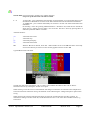
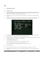
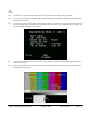
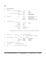
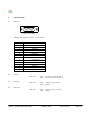
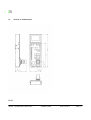
dTs 2050A
OPERATIONAL CONTROL UNIT
USER GUIDE
Document no. 2050-10-01
dTs
DIGITAL TELEVISION SYSTEMS LTD
15-16 Plantagenet House Kingsclere Park Kingsclere
Tel : +44 (0)1635 298421
www.triax.tv
Newbury
RG20 4SW England
Fax : +44 (0)1635 299287
dTs
Document Revisions
Pages
Ref
Date
S/W Rev
A
All
New Document - provisional
02/04/2009 2050AB2-2
B
4, 6, 8, 9,10,11,12
Ammended for new features.
14/03/2011 V3.1 or above
2050A Operational Control Unit
USER GUIDE
2050-10-01A
Page 2
dTs
Contents
Page
1
Contacts
4
2
General Description
4
3
Configuration
3.1
Re-Programming Software/Firmware
4
4
4
Installation
4.1
General
4.2
Power
4.3
Control Interfacing
4.3.1
RS422
4.3.2
RS232
4.3.3
Sony bi-directional
4.3.4
Panasonic bi-directional
4.4
Tally inputs
4.5
Preview output
4.6
Video input
4.7
Video output
4.8
Joystick Tension
4.9
Environmental
5
5
5
5
5
5
5
5
5
5
6
6
6
6
5
Controls
5.1
Variable Adjust Buttons
5.2
Rotary Encoder
5.3
Function Buttons
5.4
Joystick Controls
7
7
8
8
10
6
Engineering setup
6.1
Emulation selection
6.2
I/O selection
6.3
Tally selection
6.4
Joystick PED and IRIS calibration
6.5
LED Illumination Test
11
11
11
11
11
12
7
On Screen Display (OSD)
13
8
Specifications
14
9
Connectors
9.1
Main I/O
15
15
10 Physical Dimensions
16
2050A Operational Control Unit
USER GUIDE
2050-10-01A
Page 3
dTs
1
2
CONTACTS
Web
www.triax.tv
or
Sales
[email protected]
Technical support
[email protected]
Telephone
please see our web site
www.dts-dsp.co.uk
GENERAL DESCRIPTION
The dTs 2050 Operational Control Unit provides remote control facilities for a range of broadcast cameras/camcorders
from several different manufacturers. It has been designed to emulate many control units from Hitachi, JVC,
Panasonic and Sony. Refer to ‘2050 Emulations’ for types and details of available controls. Other emulations may be
selectable. The 2050 also interfaces directly with dTs Biax/Triax Broadcast Camera Control systems.
The 2050 provides reliable, noise free, non-contact joystick controls of iris, pedestal and preview.
Joystick tension adjustment is also available.
The main connector is a 15way D type which is reliable, economical and readily available. Four different I/O
interfaces are available at this connector together with red and green tally inputs and preview volt free contacts.
Preview is also available on a BNC coax connector. Video Monitor input and video output are available as standard on
bnc connectors.
Multiple non-volatile storage and retrieval scene files are available both internally and via SD card access. The SD
card allows scene file settings to be transported across multi-channel systems as well as off-site backup.
An On Screen Display (OSD) video output provides operational information and SD scene file access menus. This
OSD output can be connected to a standard definition monitor. Optionally a 3.5 inch (89mm) TFT-LCD unit is
available (dTs 2060) which is ergonomically designed to match and fit the 2050. It displays the OSD and may be
tilted up to 45° for optimum user viewing angle.
The 2050 will function over a large supply voltage range with low power consumption. If the TFT-LCD is fitted this
supply voltage range is reduced.
For in-desk fitment the low profile design of only 40mm below desktop surface gives maximum under desk clearance.
Panel mounting brackets are available for this purpose.
3
CONFIGURATION
The 2050 Operational Control Unit has been supplied configured to emulate the control panels specified on your order
or otherwise agreed. Other emulations may be included in the software version installed and if so can be selected.
Should you wish to change the emulation for a different panel which is not included, please contact the factory.
3.1
Re-Programming Software/Firmware
The OCU may be field re-programmed with software/firmware updates. Two programming connectors are available
underneath the rear connector panel, one for processor software and the other for FPGA firmware. To access these
remove the two connector panel adjusting screws (in the slots either side) and raise the panel up. The connectors are
marked appropriately.
An optional programming kit is available for this purpose. Software and the re-programming procedure are available
from dTs Customer Support.
2050A Operational Control Unit
USER GUIDE
2050-10-01A
Page 4
dTs
4
INSTALLATION
4.1
General
The unit has low power dissipation and does not require any special ventilation requirements. It may be used free
standing or with optional brackets, mounted into a desk top. All cables leave the OCU from the rear. Because of the
unit’s low profile height, the rear connector panel may be tilted downwards to provide easier access as necessary for
cabling when mounted in-desk. To do this loosen the screw either side of the connector panel (in the slot) and tilt the
panel as required, re-tighten the screws.
4.2
Power
Power input must be within the range defined in the specification. This is a DC voltage and is supplied via the
‘MAIN I/O’ cable from either the camera or camera base station.
NOTE: When a 2060 TFT-LCD display is fitted the power supply voltage range is reduced. See specification.
If the camera/camcorder/system does not have enough power to supply the OCU and/or TFT-LCD, an optional
connector and AC adaptor are available for powering the units externally.
4.3
Control Interfacing
The OCU has 4 electrical control interfaces which are automatically determined when each emulation is selected.
However, they can be changed via ENGr menu if necessary for type and sense:
4.3.1
RS422 - providing differential signals in and out (4 wire). This format offers longer distance capability should it be
necessary. For convenience in some applications the input can be switched to single ended operation. The RS422 is
the usual interface used by most cameras/systems either differentially or single ended.
4.3.2
RS232 – alternative standard data type.
4.3.3
Sony bi-directional single wire. Allows the OCU to interface directly with certain Sony systems.
4.3.4
Panasonic bi-directional single wire. Allows the OCU to interface directly with certain Panasonic systems.
4.4
Tally Inputs
Both red and green tally inputs are available. These can be configured for either voltage or contact closure. Voltage
must be positive reference ground. Contact closure is also reference ground. An open collector bipolar NPN
transistor or open drain N channel FET may also drive the inputs. Configuration is via ENGr Menu.
The panel tally LED is a bi-colour red/green with the priority red.
4.5
Preview Output
A volt-free solid state contact closure is available as standard. This is activated whilst the joystick knob is pushed
down. Observe the contact ratings defined in the specifications. The contacts are not polarity conscious.
2050A Operational Control Unit
USER GUIDE
2050-10-01A
Page 5
dTs
4.6
Video Input
The video BNC input is terminated in 75 ohms and accepts standard definition PAL\NTSC 1V p-p video composite sync, Y or VBS.
4.7
Video Output
A valid PAL\NTSC video input is switched directly to the video output. Standard selection is automatic. Whilst the
MON button is activated, the OSD characters are superimposed onto the video in white with a black border to make
them easily readable with varying program content. If no video input is applied then the video output is Composite
Sync with black background and OSD superimposed, without colour subcarrier. BNC output video is sourced in 75
ohms and gives 1V p-p when correctly terminated in 75 ohms. The output video is also available on the muli-way
connector for the optional 3.5 inch TFT-LCD display (2060).
4.8
Joystick Tension
Joystick tension may be adjusted to personal preference using the adjuster screw, which is accessible through a hole
in the under side of the unit directly under the centre of the joystick when centrally positioned.
4.9
Environmental
As with all electronic equipment, both high and low extremes of temperature should be avoided as well as the
ingress of moisture and dust. The units are rugged in construction but sharp shocks and high levels of vibration must
also be avoided. Keep the unit within the limits defined in the specification.
2050A Operational Control Unit
USER GUIDE
2050-10-01A
Page 6
dTs
5
CONTROLS
PLEASE NOTE:
The following descriptions indicate the full potential control of the 2050 OCU but do NOT imply that all controls
are available for any particular control panel emulation. Cameras and controllers differ considerably in the
functionality they offer. Refer to ‘2050 Emulations’ for available control features. All camera settings and
adjustments must be read with reference to the emulated control panel and specific camera manuals.
5.1
VARIABLE ADJUST BUTTONS
Description
The variable adjust buttons along the OCU left side allow digital bit increment and decrement of the parameter
selected with the rotary encoder. A flashing illuminated variable button means that the rotary encoder is active for
this item. The ‘adjust’ LED should be illuminated. The variable value is shown on the OSD. A steady illuminated
variable button means the parameter value previously varied is now fixed and operational.
To adjust a parameter, select by pressing the appropriate button once. The button will flash if the parameter is
available. The camera will be updated with the value associated with the parameter and adjustment can be made.
If the button is pushed again the LED will extinguish and the previous parameter value will be reinstated. To retain
the adjusted value, leave the LEDs on.
If another parameter adjustment is required, press the appropriate button. The previous button will go to steady
illumination indicating that it’s particular value has been retained and the new button will flash indicating the new
parameter adjustment active.
To switch off a previously fixed parameter, press it’s button twice. Once will force the parameter adjustment active
and the second will turn it off.
SHUTTER
Variable adjustment of shutter value.
RED GAIN
Adjusts red amplitude level
BLUE GAIN Adjusts blue amplitude level
RED PED
Adjusts red pedestal (black) level
BLUE PED
Adjusts blue pedestal (black) level
KNEE
Adjusts the variable knee camera characteristic.
Alternate function - Moves menus up/page/values
∧
GAMMA
<
DETAIL
>
IRIS
∨
Adjusts the camera gamma characteristic.
Alternate function - Moves menus left
Adjusts the picture edge detail. Sometimes called ‘Contour’.
Alternate function - Moves menus right/values
Inhibits the joystick IRIS control. Rotary encoder varies the iris. Selecting IRIS AUTO reduces the
sensitivity of control, allowing small variation of the auto setting. This is camera dependant. Some
cameras do not allow any adjustment in IRIS AUTO mode.
Alternate function - Moves menus down
2050A Operational Control Unit
USER GUIDE
2050-10-01A
Page 7
dTs
5.2
ROTARY ENCODER
The encoder allows bit increment and decrement of the selected parameter digital value.
The encoder also has a push switch which can be used for selecting functions e.g. ENGr Menu, Camera Menu and
SD card items. Colour adjustments can also be selected by pressing the push switch.
If either ‘RED GAIN’ or ‘BLUE GAIN’ LEDs are active (flashing), pushing the switch will swap control to the
other. Some emulations combined with certain camera models may also allow ‘GREEN GAIN’ to be selected.
If either ‘RED PED’ or ‘BLUE PED’ LEDs are active (flashing), pushing the switch will swap control to the other.
Some emulations combined with certain camera models may also allow ‘GREEN PED’ to be selected.
5.3
FUNCTION BUTTONS
ON/OFF
OCU on/off
Toggles the OCU on/off. On power-up, the LED flashes indicating that the OCU is trying to acquire
comms with the camera. The LED attains steady state when comms are correctly established and the
last saved scene file has been recalled and applied.
CALL
Performs call function with the camera. Usually this means flashing the tally lights on the camera
and the viewfinder. This can vary with camera type or camera settings.
VTR
Switches the scene file and MODE buttons to VTR mode - on or off as applicable.
BARS
Toggles camera colour bars on and off.
MON
Switches on or off the monitor On Screen Display characters (OSD) .
MENU
Switches the camera menu on and off if applicable. When on, the rotary encoder is enabled for item
selection and adjustment.
ENGr
Switches on and off the Engineering setup menus.
SHUTTER< > Increments or decrements the fixed shutter value shown on the OSD.
GAIN< >
Increments or decrements the fixed gain value shown on the OSD.
BALANCE
Colour
Preset
Auto1
Auto2
ABB
AWB
Enables variable adjustment of the 4 colour balance controls
Sets the camera internal preset colour balance levels
Applies auto balance 1
Applies auto balance 2
Performs an auto black balance
Performs an auto white balance
Depending on camera model and emulation type, colour balance adjustments are made relative to an AWB or ABB.
2050A Operational Control Unit
USER GUIDE
2050-10-01A
Page 8
dTs
SCENE FILE Saves and recalls 5 complete OCU settings internally.
On power-up the last saved scene file is recalled.
1– 4
To save a file - press and hold the selected button for approximately 2.5 seconds until all four scene
file buttons are illuminated. On release of the button the selected scene file button then illuminates.
To recall a file - press a button momentarily for less than 2 seconds. The selected file button then
illuminates.
De-selecting a scene file (pressing illuminated button - all buttons off) recalls the user default file
which can be a starting point for setting a new scene file. This file is stored by pressing button 1
followed by button 4 within 2.5 seconds.
Alternate functions:
<<
VTR mode fast rewind
¦
VTR mode stop
VTR mode pause/play
VTR mode fast forward
||?
>>
SD
When an SD card is inserted, Scene File 1 button enables access to the SD OSD menu. Previously
stored scene files may be retrieved or the currently applied scene file saved to SD.
Typical SD scene file OSD menu.
The SD card must first be formatted on a PC to create a FAT16 Master Boot Record. The card can then be
formatted in the unit by selecting the ‘Format Card’ option.
When selecting a scene file to be saved the filename will change to indicate the one selected. In the example above
Scene File 4 has been selected for saving. The filename can be edited using the ‘Change Description’ option before
saving.
When retrieving the scene file using the load option, the scene file is loaded into the scene file 1 position. To
transfer these settings to another scene file, exit the SD Menu and save to one of the other available locations, e.g.
Scene File 2.
2050A Operational Control Unit
USER GUIDE
2050-10-01A
Page 9
dTs
KNEE
Preset
Auto
Adjust the camera variable knee characteristic.
Sets the camera preset knee value.
Selects the camera auto knee function.
BLACK
STRETCH
Adjusts the picture in the black region allowing more picture detail to be seen.
This feature is not available on all camera models.
Alternate functions:
The Black Stretch button also operates the VTR REC PREVIEW function available on
certain camera models.
IRIS AUTO
Sets camera auto iris mode. Most cameras automatically adjust iris to the correct level and allow
small adjustment of this level via the joystick ‘IRIS’ or variable controls.
MODE
When ‘MODE’ is off, camera iris values are updated immediately when switching from the variable
IRIS control and the Joystick Iris control.
When ‘MODE’ is ON joystick IRIS adjustments acquire control only when the current camera
(variable) values and joystick control values are equal. This prevents potentially large changes
occurring after switching and when not desired (e.g. live on air).
The ‘IRIS’ and ‘PED’ LEDs only illuminate when the controls are active.
In some emulations and firmware versions the ‘MODE’ button has additional functions selectable by
multiple presses and indicated by the adjacent LEDs.
MODE 1 - Iris Value remains as set by variable control until joystick reaches position to acquire.
MODE 2 - When selected ‘locks’ the Joystick Master Pedestal control to prevent accidental
adjustment.
MODE 3 – MODE 1 & 2 combined as indicated by LED 1 & 2 lit.
Pressing mode again returns to default condition OFF.
Alternate functions:
Rec
5.4
VTR mode record if media is present in camcorder
JOYSTICK CONTROLS
IRIS
Control of the lens iris using non-contact technology for noiseless, smooth and reliable operation.
When the IRIS LED is illuminated the Joystick IRIS is in control. Whilst IRIS Auto is selected,
Joystick IRIS has a reduced control dependant on camera type. Whilst IRIS Var is selected, Joystick
IRIS is turned off. See ‘MODE’ for additional information.
PEDESTAL
Controls video black level pedestal. Also uses non-contact technology. When the MASTER PED
LED is illuminated the Joystick PED is in control. See ‘MODE’ for additional information.
PREVIEW
Pushing the joystick downwards enables the preview volt-free contact closure. This electronic circuit
uses a non-contact sensor and a solid state output relay for reliability.
2050A Operational Control Unit
USER GUIDE
2050-10-01A
Page 10
dTs
6
ENGINEERING Setup
6.1
Emulation Selection.
6.1.1
Connect the unit to the camera and turn on the power to the camera head. Alternatively, connect the unit to an
appropriate AC adaptor (Please see specifications section for power supply.) If no 2060A TFT module is fitted then
connect the Video Output BNC of the unit to an external monitor.
6.1.2
Select MON to turn on the On Screen Display and then ENGR Menu. The first page of the ENGR Menu will be
displayed.
6.1.3
Using the rotary control, select ‘SET EMULATION’ and push down once. The appropriate emulation type can now
be selected by scrolling through the available options and pressing down on the rotary control to confirm.
6.1.4
Once the appropriate emulation type is confirmed, scroll down to ‘SET COMMS’ and select by pressing down on
the rotary control. This will automatically set the required I/O parameters.
6.1.5
Exit the ENGR Menu to confirm all of the settings. If connected to a camera then it may also be necessary to switch
the camera head OFF/ON for communication to be established.
6.2
Joystick PED and IRIS calibration.
The iris range of the joystick can be adjusted to suit individual users or cameras.
Note: a camera/camcorder is required to be connected and operational.
The OCU Joystick must be in control of the camera iris – the blue iris led must be on.
6.2.1
Turn AUTO IRIS off.
6.2.2
Position the joystick fully back towards you and set MASTER PEDESTAL at mid-point (12 O’clock.)
6.2.3
Select ENG MENU and using the rotary control click on NEXT MENU until you reach the page displaying CAL
JOY/PED.
2050A Operational Control Unit
USER GUIDE
2050-10-01A
Page 11
dTs
6.2.4
Scroll down to CAL JOY/PED and click with the rotary push button. The display will report DONE.
6.2.5
Scroll up to the menu option JOYSTICK MIN and click with the rotary push button. The display will report BUSY
and display the iris value.
6.2.6
Use the rotary control to set the IRIS to Closed position, ideally by viewing the iris ring on the lens of the camera. If
this is not possible due to the location of the camera then set the iris value to the CLOSED position according to the
On Screen Display message (see notes below.)
6.2.7
Once the iris is set to the closed position, click the rotary control to confirm the setting and the display will change
from BUSY to DONE.
6.2.8
Push the joystick all the way forward and scroll to select JOYSTICK MAX. Click with the rotary push button and
the display will report BUSY.
2050A Operational Control Unit
USER GUIDE
2050-10-01A
Page 12
dTs
6.2.9
Use the rotary control to set the IRIS to the fully open position, ideally by viewing the iris ring on the lens of the
camera. If this is not possible due to the location of the camera then set the maximum iris value to the OPEN
position according to the On Screen Display message (see notes below.)
6.2.10
Once the iris is set to the open position, click the rotary control to confirm the setting and the display will change
from BUSY to DONE.
6.2.11
Exit the ENG MENU and check that the iris can be controlled by the joystick across the complete range.
NOTES.
Some Sony camera models allow iris adjustment across a range between approximately 038 minimum and 110
maximum only.
The above procedure can also be used to set the whole physical range of the joystick to control a limited range of Iris
values. For example, with the joystick fully backward, the minimum iris position can be set to F8 and with the
joystick fully forward the maximum set to F2.8. A large movement of the joystick controls then results in a small
camera iris movement for fine control.
6.3
LED Illumination Test
Note that a camera/camcorder does not need to be connected.
Switch the OCU OFF.
Press and hold ENGr button, press the ON/OFF button. Release buttons.
The test will start by illuminating tally and then illuminate the buttons in groups and end with the blue leds. The
OCU will then revert to normal operation.
Note that the SHUTTER and GAIN buttons do not illuminate.
2050A Operational Control Unit
USER GUIDE
2050-10-01A
Page 13
dTs
7
OSD Output
The OSD output provides various on screen camera control information as well as SD card memory information
and control. The characters will be superimposed on a valid video input. If no video input is present the OSD
outputs black background.
The video output is fed to the rear panel BNC connector and also to the miniature multiway connector for the
optional TFT-LCD colour display (2060).
Shutter:
off
Gain: +3dB
Typical on Screen information (simulated)
Red Gain:
128
Shutter: 1/500
Gain:
0dB
Typical on screen information whilst Red Gain is
selected for variable adjustment. (simulated)
2050A Operational Control Unit
USER GUIDE
2050-10-01A
Page 14
dTs
8
SPECIFICATIONS
8.1
Power Input
OCU 2050 only voltage
Power (@12V)
With 2060 Display Fitted voltage
power (@12V)
8.2
Serial control
type
8 – 48
1.5W
3.5W
10 > 14
5.5 W
7W
VDC
typical
maximu m
VDC
combined typical
combined maximum
RS422
Differential I/O (4 wire + gnd)
Or Single ended i/p
I/O (2 wire + gnd)
bi-directional (1 wire + gnd)
bi-directional (1 wire + gnd)
RS232
Sony
Panasonic
8.3
Tally input (red & green)
Voltage
level off
level on
resistance
max i/p
0V (Gnd)*
+5V*
10K
+20V
CMOS
Levels
level off
level on
resistance
open circuit
connect to 0V (Gnd)
10K to +5V
Contact
* Nominal logic sense - levels and sense may vary depending on panel emulation and menu settings.
8.4
REM /EN o/p
level off
+5V
(when ON/OFF LED is off)
0V
(when ON/OFF LED is on or flashing)
100V
maximum
120mA
AC maximum
250mA
DC maximum
25ohms
maximum
5000Vrms
maximum
level on
8.5
Preview Contacts o/p
voltage
current
on resistance
isolation
8.6
Video input and Output
PAL or NTSC
8.7
Compatibility
see ‘2050 Emulations’ Chart
8.8
Size
see para 9 – Physical Dimension Drawing
2050A Operational Control Unit
USER GUIDE
2050-10-01A
Page 15
dTs
9
CONNECTORS
9.1
Main I/O
1
2
3
4 5
6
7
8
9 10 11 12 13 14 15
D Type –15way Plug
(Mating cable connector: D Type – 15way Socket)
Pin Number
1
2
3
4
5
6
7
8
9
10
11
12
13
14
15
9.2
9.3
9.4
MAIN I/O
Function
GND
RS422 Out+
RS422 InREM /EN
+SUPPLY
PREVIEW 1
PREVIEW 2
GND
TALLY RED
RS422 OutRS422 In+
TALLY GREEN
RS232 In
RS232 Out
Bi-Directional I/O
Preview
BNC coax
inner
Outer
Preview1 (volt free contact 1)
Preview2 (volt free contact 2)
BNC coax
inner
Outer
video in 1V p-p 75 ohms
ground
BNC coax
inner
Outer
video out 1V p-p 75 ohms
ground
Video In
Video Out
2050A Operational Control Unit
USER GUIDE
2050-10-01A
Page 16
dTs
10
PHYSICAL DIMENSIONS
E&OE
2050A Operational Control Unit
USER GUIDE
2050-10-01A
Page 17