1
Elo Entuitive Touchmonitor
User Guide
17" LCD Desktop Touchmonitor
with Magnetic Swipe Reader
1725L Series
Revision A
P/N 008583
Elo TouchSystems, Inc.
1-800-ELOTOUCH
www.elotouch.com
Copyright © 2004 Elo TouchSystems, Inc. All Rights Reserved.
No part of this publication may be reproduced, transmitted, transcribed, stored in a retrieval system,
or translated into any language or computer language, in any form or by any means, including, but not
limited to, electronic, magnetic, optical, chemical, manual, or otherwise without prior written
permission of Elo TouchSystems.
Disclaimer
The information in this document is subject to change without notice. Elo TouchSystems makes no
representations or warranties with respect to the contents hereof, and specifically disclaims any
implied warranties of merchantability or fitness for a particular purpose. Elo TouchSystems reserves
the right to revise this publication and to make changes from time to time in the content hereof
without obligation of Elo TouchSystems to notify any person of such revisions or changes.
Trademark Acknowledgments
IntelliTouch, SecureTouch, AccuTouch, Entuitive, and MonitorMouse are trademarks of Elo
TouchSystems, Inc.
Other product names mentioned herein may be trademarks or registered trademarks of their
respective companies. Elo TouchSystems claims no interest in trademarks other than its own.
iii
Table of Contents
Chapter 1
Chapter 4
Introduction
1
Troubleshooting
23
Precautions . . . . . . . . . . . . . . . . . . . . 1
About the Product . . . . . . . . . . . . . . . . . 1
Solutions to Common Problems . . . . . . . . 23
Chapter 2
Native Resolution
Installation and Setup
Appendix A
3
Appendix B
Unpacking Your Touchmonitor. . . . . . . . . . . 3
Product Overview . . . . . . . . . . . . . . . . . 4
Main Unit . . . . . . . . . . . . . . . . . . . . 4
Rear View . . . . . . . . . . . . . . . . . . . 4
Side View. . . . . . . . . . . . . . . . . . . . 5
Base Bottom View . . . . . . . . . . . . . . . 5
Touch Interface Connection . . . . . . . . . . . . 6
Serial or USB Connection . . . . . . . . . . . 6
Removing the Back Cover . . . . . . . . . 7
Routing the Cables . . . . . . . . . . . . . 8
Connecting the Video Cable or DVI-D Video
Cable . . . . . . . . . . . . . . . . . . . . 9
Connecting the Serial or USB Touchscreen
Cable . . . . . . . . . . . . . . . . . . . 10
Connecting the Speaker Cable . . . . . . 11
Connecting the Power Cable . . . . . . . 12
Replacing the Back Cover . . . . . . . . 12
Optimizing the LCD Display . . . . . . . . . . . 13
VESA Mount on Your Touchmonitor . . . . . . . 13
Accessing the VESA Mounting Interface. . . 14
Mounting the Base . . . . . . . . . . . . . . . 14
Installing the Driver Software . . . . . . . . . . 15
Installing the Serial Touch Driver for Windows
XP, Windows 2000, Me, 95/98 and NT 4.0 . 16
Installing the Serial Touch Driver for MS-DOS
and Windows 3.1 . . . . . . . . . . . . . 17
Installing the USB Touch Driver . . . . . . . 18
Installing the USB Touch Driver for Windows
XP, Windows 2000, Me and 98 . . . . . . 18
Touchmonitor Safety
About Touchmonitor Adjustments . . . . . .
Using the On-Screen Display (OSD) Menus
Side Bezel Buttons . . . . . . . . . . . . .
OSD Menu Function. . . . . . . . . . . . .
Appendix C
Technical Specifications
Compatible Video Modes . . . . . . . . . .
Touchmonitor Specifications . . . . . . . .
17" LCD Touchmonitor (ET17-XXWF-1)
Specifications . . . . . . . . . . . . .
IntelliTouch Touchmonitor Specifications
AccuTouch Touchmonitor Specifications.
17" LCD Touchmonitor Dimensions . . . . .
19
.
.
.
.
.
.
.
.
27
Care and Handling of Your Touchmonitor . . . . 28
Chapter 3
Operation
25
19
19
20
21
iv
29
. . 29
. . 30
.
.
.
.
.
.
.
.
30
31
32
33
Regulatory Information
Warranty
35
39
Index
41
MSR Serial Reference Manual
MSR USB Reference Manual
Programming Reference Manual
43
76
131
CHAPTER
1
INTRODUCTION
CHAPTER 1
Congratulations on your purchase of an Elo TouchSystems Entuitive
touchmonitor. Your new touchmonitor combines the reliable performance of
Elo’s touch technology with the latest advances in LCD display design. This
combination of features creates a natural flow of information between a user
and your touchmonitor.
Precautions
Follow all warnings, precautions and maintenance as recommended in this
user’s manual to maximize the life of your unit. See Appendix B for more
information on touchmonitor safety.
About the Product
Your LCD Desktop Touchmonitor is a 17" XGA TFT color display with the
following features:
• Direct analog RGB input
• 17" diagonal screen size
• 16.7 million displayable colors
• 1280 x 1024 resolution
• SXGA/XGA/ SVGA/ VGA/VESA/ Mac compatible
• 30kHz~80 horizontal scan
• 56~75Hz refresh rate
1-1
• Auto adjustment capability
• High quality full screen re-scaling
• Multilingual OSD menus in six languages: English, French, German,
Spanish, Italian and Japanese
• Serial or USB touch interface (USB requires Windows 98, 2000, Me and
XP.)
• Built in speakers with volume, treble, bass And balance control thorough
OSD
• Patented touch technology of Elo TouchSystems
• VESA DDC 1/2B data communication
• VESA DPMS power saving
• Stand with minimum 95° angle of tilt.
• Cable management device
• VESA flat panel monitor physical mounting interface (Both 75 & 100mm)
• OSD and Power button lockouts
• Wall mountable with existing stand
• VESA 100 mm M5 threaded holes on bottom of stand for securing to desk or
other surface, i.e. table top
• Cable strain reliefs for all cables
For full Product Specifications refer to Appendix C.
1-2
Elo Entuitive Touchmonitor User Guide
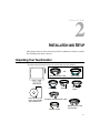
CHAPTER
2
INSTALLATION AND SETUP
CHAPTER2
This chapter discusses how to install your LCD touchmonitor and how to install
Elo TouchSystems driver software.
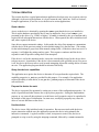
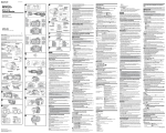
Unpacking Your Touchmonitor
Check that the following 9 items are present and in good condition:
OR
USB touchscreen cable
Serial cable
LCD Display
Quick Install Guide
CD
Software
User Guide-on CD,
Quick Install Guide
and software CD
Video cable
Adapter
DVI-D video
cable
European monitor power cable
Speaker Cable
Monitor power cable
(US/Canada)
2-3
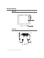
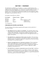
Product Overview
Main Unit
LCD Display
Stand
Rear View
2-4
Elo Entuitive Touchmonitor User Guide
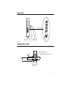
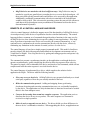
Side View
User Controls
Base Bottom View
100
5X Stability Pad
23.6
123.2
M5 Mounting Holes (4X)
100
86.6
100
Base Bottom
Scale 1:4
2-5
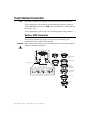
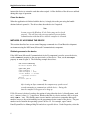
Touch Interface Connection
NOTE:
Your interface cables may have been pre-connected to your monitor at the factory.
Your touchmonitor comes with one of the following touchscreen connector
cables: Serial (RS-232) cable or USB cable. (For Windows 98, 2000, Me and
XP systems only.)
To set up this display, please refer to the following figures and procedures:
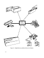
Serial or USB Connection
The following illustrations guide you step by step in connecting your
touchmonitor using a serial cable connection.
CAUTION
Before connecting the cables to your touchmonitor and PC, be sure that the computer
and the touchmonitor are turned off.
OR
USB cable
Serial touchscreen
cable
Speaker cable
Removable back cover
Video cable
Connections on underside
Monitor
power cable
(US/Canada)
USB connector
European monitor
power cable
Power Speaker
port
Female DVI-D
video connector
Female 15-pin
video connector
Female 9-pin serial
Touchscreen connector
DVI-D cable
Adapter
2-6
Elo Entuitive Touchmonitor User Guide
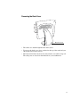
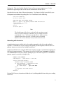
Removing the Back Cover
Bottom cut-out
• The cables are routed through the back of the stand.
• To remove the back cover, place one hand at the top of the stand and your
other hand on the bottom cut-out.
• Pull forward from the bottom cut-out and twist the cover until it snaps off.
The cable ports are located on the underside of your touchmonitor.
2-7
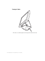
Routing the Cables
• The cables are routed through the cable management channel in the stand.
2-8
Elo Entuitive Touchmonitor User Guide
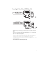
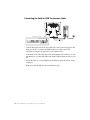
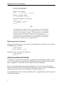
Connecting the Video Cable or DVI-D Video Cable
Connections on underside
Video cable
Female 15 pin Video connector
OR
Video cable
Connections on underside
Video port
Female DVI-D Video connector
Video cable
• Tilt the screen up and out (away from the stand) to access the connection
ports.
• Connect the 15-pin video cable (the ferrite bead end) or the 24-pin DVI-D
cable to the video port on your PC.
• Connect the other end of the video cable to the video connector on your
touchmonitor by routing the cable through the hole in the stand.
• Secure the cable to your touchmonitor and PC by turning the screws on the
connector clockwise.
• Place the cable in the cable management clip.
2-9
Connecting the Serial or USB Touchscreen Cable
Connections on underside
USB Touchscreen connector
Serial Touchscreen cable
Female 9-pin serial
Touchscreen connector
• Connect the female end of the serial (RS-232) cable to the serial port on the
back of your PC, or connect the USB touchscreen cable to the USB
touchscreen connector on the back of your touchmonitor.
• Connect the male end of the cable to the serial touchscreen connector on your
touchmonitor, or connect the other end of the USB touchscreen cable to your
PC.
• Secure the cable to your touchmonitor and PC by turning the screws on the
connector.
• Route the cable through the cable management clip.
2-10
Elo Entuitive Touchmonitor User Guide
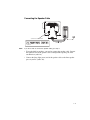
Connecting the Speaker Cable
CONNECTIONS ON UNDERSIDE
SPEAKER CABLE
Speaker port
NOTE:
If you do not wish to connect the speaker cable, go to step 5.
• To use the built in speakers, you need to connect the speaker cable. Connect
the light blue end of the speaker cable to thelight blue speaker port of the
touchmonitor (audio in).
• Connect the lime (light green) end of the speaker cable to the lime speaker
port on your PC (audio out).
2-11
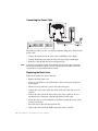
Connecting the Power Cable
Connections on Underside
Power Cable
Power
Brick Power Supply
Depending on where you live, you will use either the European or US/Canadian
power cable.
• Connect the female end of the power cable to theBrick power supply.
• Connect the Brick power cable into the power port on the touchmonitor.
• Route the cable through the cable management clip.
NOTE:
To protect your equipment against risk of damage from electrical surges in the power
line, plug the touchmonitor’s power cord into a surge protector, and then connect the
surge protector to a grounded AC electrical outlet.
Replacing the Back Cover
When all the cables have been connected:
• Replace the back stand cover.
• Power on your PC then your touchmonitor. After a brief pause the picture
should appear.
• Tilt the screen up and back to access the connection ports.
• Connect the 15-pin video cable (the ferrite bead end) to the video port on
your PC.
• Connect the other end of the video cable to the video connector on your
touchmonitor by routing the cable through the hole in the stand.
• Secure the cable to your touchmonitor and PC by turning the screws on the
connector clockwise.
• Place the cable in the cable management clip.
• Connect the other end of the USB touchscreen cable to your PC.
2-12
Elo Entuitive Touchmonitor User Guide
Optimizing the LCD Display
To ensure the LCD display works well with your computer, configure the
display mode of your graphic card to make it less than or equal to 1024 x 768
resolution, and make sure the timing of the display mode is compatible with the
LCD display. Refer to Appendix A for more information about resolution.
Compatible video modes for your touchmonitor are listed in Appendix C.
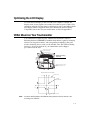
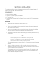
VESA Mount on Your Touchmonitor
Your touchmonitor conforms to the VESA Flat Panel Monitor Physical
Mounting Interface (FPMPMI™) Standard which defines a physical mounting
interface for flat panel monitors, and corresponding standards for flat panel
monitor mounting devices, such as wall and table arms. The VESA mounting
interface is located on the back of your touchmonitor and is shipped
pre-connected to the base.
Remove these four screws
(retain for reassembly)
VESA mounting
interface
115
VESA mounting surface is located
12mm below the surface of the
plastic.
115
Wall mount/Surface mount template
100
Customer wall
(4X) M5
clearance hole
65
100
70 X 30 cable access hole
NOTE:
The above drawing displays the VESA mounting interface after the removal of the
mounting cover and base.
2-13
Accessing the VESA Mounting Interface
If you want to convert your desktop monitor to a wall mount or kiosk monitor,
follow the steps below to access the VESA mounting interface.
NOTE:
You will need a screwdriver for the following steps.
1 Remove the back cover of the stand by pulling forward on the bottom
cut-out.
2 Carefully lay the monitor face down. At the top of the mounting screw cover
there are two slots. With a screwdriver, pry open the mounting screw cover.
The cover fit is tight so remove it carefully.
3 When you remove the mounting screw cover, you will see four screws.
Remove the screws to mount your monitor. Refer to the drawing on page 18.
The following companies provide VESA mounting devices compatible with
your touchmonitor:
Ergotron
800-888-8458
651-681-7600
www.ergotron.com
Innovative Office Products
800-524-2744
610-253-9554
www.innov-office-prod.com
GCX
800-228-2555
707-773-1100
www.gcx.com
MRI
800-688-2414
www.mediarecovery.com
Mounting the Base
You can also mount your touchmonitor by using the keyholes in the base of the
stand. These keyholes provide easy slide on mounting. You can also bolt your
touchmonitor to a tabletop or other flat surface. Please refer to Appendix C for
location and dimension of the mounting holes.
2-14
Elo Entuitive Touchmonitor User Guide
Installing the Driver Software
Elo TouchSystems provides driver software that allows your touchmonitor to
work with your computer. Drivers are located on the enclosed CD-ROM for the
following operating systems:
• Windows XP
• Windows 2000
• Windows Me
• Windows 98
• Windows 95
• Windows NT 4.0
Additional drivers and driver information for other operating systems are
available on the Elo TouchSystems web site at www.elotouch.com.
Your Elo touchmonitor is plug-and-play compliant. Information on the video
capabilities of your touchmonitor is sent to your video display adapter when
Windows starts. If Windows detects your touchmonitor, follow the instructions
on the screen to install a generic plug-and-play monitor.
Refer to the appropriate following section for driver installation instructions.
2-15
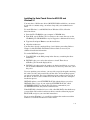
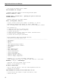
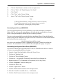
Installing the Serial Touch Driver for Windows XP,
Windows 20001, Me, 95/98 and NT 4.0
NOTE:
For Windows 2000 and NT 4.0 you must have administrator access rights to install the
driver.
1 Insert the Elo CD-ROM in your computer’s CD-ROM drive.
If the AutoStart feature for your CD-ROM drive is active, the system
automatically detects the CD and starts the setup program.
2 Follow the directions on the screen to complete the driver setup for your
version of Windows.
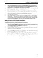
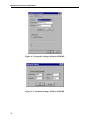
If the AutoStart feature is not active:
1 Click Start > Run.
2 Click the Browse button to locate the EloCd.exe program on the CD-ROM.
3 Click Open, then OK to run EloCd.exe.
4 Follow the directions on the screen to complete the driver setup for your
version of Windows.
1.To install Windows 2000 and Windows XP, you must use the "update driver"
method; you will not find a setup.exe file within the download.
2-16
Elo Entuitive Touchmonitor User Guide
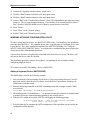
Installing the Serial Touch Driver for MS-DOS and
Windows 3.1
You must have a DOS mouse driver (MOUSE.COM) installed for your mouse
if you wish to continue using your mouse along with your touchmonitor in
DOS.
To install Windows 3.x and MS-DOS from Windows 95/98, follow the
directions below:
1 Insert the Elo CD-ROM in your computer’s CD-ROM drive.
2 From DOS, type d:\EloDos_W31 to change to the correct directory on the
CD-ROM (your CD-ROM drive may be mapped to a different drive letter).
3 Type install and press Enter to start the installation.
4 Align the touchscreen.
You must have already completed Steps 1 and 2 before proceeding. Refer to
Chapter 2 of the Elo DOS and Windows Driver Guide as necessary for
additional installation information.
To run the INSTALL program:
1 Type INSTALL at the DOS prompt in the directory containing the driver
install files.
2 INSTALL asks you to select the software to install. Then choose
d:\EloDos_W31 from the displayed list.
3 INSTALL also asks you for the paths to use during installation, or you may
use its defaults. INSTALL creates directories as necessary, and warns you if
they exist.
If you are updating your software, you may wish to specify the paths containing
the earlier versions, and overwrite the obsolete files. All executable programs
are upward compatible. For a list of differences from each previous version of
the drivers, be sure to select "Differences from Previous Versions" during the
installation process.
INSTALL updates your AUTOEXEC.BAT file with the drivers you select.
INSTALL makes a copy of your original AUTOEXEC.BAT file, called
AUTOEXEC.OLD. If you already have Elo driver commands in your
AUTOEXEC.BAT file, they will be commented out.
When INSTALL is finished, it leaves a file called GO.BAT in the subdirectory
you specified. GO loads the touchscreen driver, runs the calibration program
ELOCALIB, and gives you some final instructions.
If you are using Windows 3.1, you will also calibrate the touchscreen within
Windows 3.1 with the Touchscreen Control Panel.
2-17
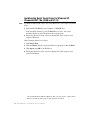
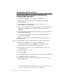
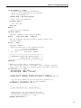
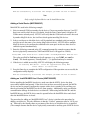
Installing the USB Touch Driver
Installing the USB Touch Driver for Windows XP,
Windows 20002, Me and 98
1 Insert the Elo CD-ROM in your computer’s CD-ROM drive.
If Windows 98, Windows Me or Windows 2000 starts the Add New
Hardware Wizard:
2 Choose Next. Select “Search for the best driver for your device
(Recommended)” and choose Next.
3 When a list of search locations is displayed, place a checkmark on “Specify a
location” and use Browse to select the \EloUSB directory on the Elo
CD-ROM.
4 Choose Next. Once the Elo TouchSystems USB touchscreen driver has been
detected, choose Next again.
5 You will see several files being copied. Insert your Windows 98 CD if
prompted. Choose Finish.
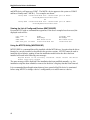
If Windows 98, Windows Me or Windows 2000 does not start the Add New
Hardware Wizard:
NOTE:
For Windows 2000 you must have administrator access rights to install the driver.
1 Insert the Elo CD-ROM in your computer’s CD-ROM drive.
If the AutoStart feature for your CD-ROM drive is active, the system
automatically detects the CD and starts the setup program.
2 Follow the directions on the screen to complete the driver setup for your
version of Windows.
If the AutoStart feature is not active:
1 Click Start > Run.
2 Click the Browse button to locate the EloCd.exe program on the CD-ROM.
3 Click Open, then OK to run EloCd.exe.
4 Follow the directions on the screen to complete the driver setup for your
version of Windows.
2.To install Windows 2000 and Windows XP, you must use the "update driver"
method; you will not find a setup.exe file within the download.
2-18
Elo Entuitive Touchmonitor User Guide
CHAPTER
3
OPERATION
CHAPTER3
About Touchmonitor Adjustments
Your touchmonitor will unlikely require adjustment. Variations in video output
and application may require adjustments to your touchmonitor to optimize the
quality of the display.
For best performance, your touchmonitor should be operating in native
resolution, that is 1280 x 1024 at 60-75 Hz. Use the Display control panel in
Windows to choose 1280 x 1024 resolution.
Operating in other resolutions will degrade video performance. For further
information, please refer to Appendix A.
All adjustments you make to the controls are automatically memorized. This
feature saves you from having to reset your choices every time you unplug or
power your touchmonitor off and on. If there is a power failure your
touchmonitor settings will not default to the factory specifications.
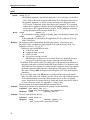
Using the On-Screen Display (OSD) Menus
All adjustments are made by using the on-screen display (OSD) menus. All
menu items can be selected by using the buttons on the side bezel.
NOTE:
OSD menu default is enabled.
3-19
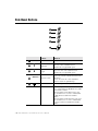
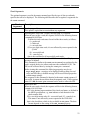
Side Bezel Buttons
1
2
3
4
5
1
Function
Menu
Display on exit the OSD menus.
2
Contrast/
Up/Toggle
3
Volume/Down
Toggle
4
5
3-20
MENU
Control
SELECT
1. Shortcut to Contrast adjustment
2. Increase value of adjustment items
3. With menu on toggles OSD options
1. Shortcut to Volume adjustment
2. Decrease value of the adjustment items
3. With menu on toggles OSD options
Enter Select item
1. Shortcut to Auto Adjust
2. Select- To select the adjustment items from the
OSD menus.
3. Auto- To activate the “Auto Adjustment”
function to obtain an optimum image.
Power Switch
Switches the power on/off to your touchmonitor.
Enable/Disable
1. Press the Up and Down buttons at the same
time to enable/disable the MUTE functions. OSD
menu default is enabled
2. Press the Menu and Up buttons at the same
time and hold for two seconds to enable/disable
the OSD functions. OSD menu default is
enabled.
3. Press the Menu and Down buttons at the same
time and hold for two seconds to enable/disable
the power lock function. OSD menu default is
enabled.
Elo Entuitive Touchmonitor User Guide
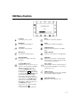
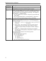
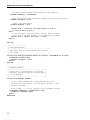
OSD Menu Function
CONTRAST
50
Contrast
Phase
Controls the picture contrast
Controls the vertical fine adjustment
Brightness
Clock
Controls the picture brightness
Controls the horizontal fine adjustment
V-Position
OSD H-Position
Controls the vertical position
Adjusts the horizontal position of the OSD
menu
H-Position
OSD V-Position
Controls the horizontal position
Adjust the vertical position of the OSD menu
Recall Defaults
OSD Time
Recalls factory settings of the image
parameters
Determines how long (in seconds) the OSD
menu waits before closing automatically after
no action has been performed.
C1/C2/USER (Color)
Auto Adjust
Using these icons, you can select one of
the preset color temperatures (9300°K or
6500°K). Confirm your choice by
pressing the SELECT button. If you
want to change the color temperatures
individually, select USER and confirm by
pressing the OSD button SELECT. Now
you can use the OSD dial to toggle
between the settings R, G and B (red,
green and blue foreground). To change a
setting, first press the SELECT button,
then choose the desired value with the
OSD dial. To confirm the setting, press
the SELECT button again.
If you don’t need to adjust any further
settings, choose the
icon to return to the OSD main menu.
Automatically selects the optional settings for
image parameters (brightness, contrast, image
position, phase, etc.)
OSD Language
Selection of the OSD menu language: English,
French, German, Spanish, Japanese.
Image Information
Displays the current graphics mode.
3-21
3-22
Elo Entuitive Touchmonitor User Guide
CHAPTER
4
TROUBLESHOOTING
CHAPTER4
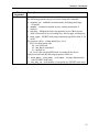
If you are experiencing trouble with your touchmonitor, refer to the following
table. If the problem persists, please contact your local dealer or our service
center.
Solutions to Common Problems
Problem
Suggestion(s)
No image appears on screen.
Check that all the I/O and power connectors are properly
connected as described in Chapter 2.
Make sure the pins of the connectors are not crooked or
broken.
Test power supply by trying different cables, a different
wall outlet or plug another appliance into the outlet.
Make certain the video cable is properly connected and that
it is not damaged. Check for bent pins on the cable
connectors.
Ensure that your computer and video card are properly
configured. (Consult video card documentation.)
“Out of Range” display
Check to see if the resolution of your computer is higher
than that of the LCD display.
Reconfigure the resolution of your computer to make it less
than or equal to 1280 x 1024. See Appendix A for more
information on resolution.
4-23
4-24
Image has vertical flickering line bars.
Use “PHASE” to make an adjustment.
Check and reconfigure the display mode of the vertical
refresh rate of your graphic card to make it compatible with
the LCD display.
Image is unstable and flickering
Use “CLOCK” to make an adjustment.
Image is scrolling
Make sure the VGA signal cable (or adapter) is well
connected.
Check and reconfigure the display mode of the vertical
refresh rate of your graphic card to make it compatible with
the LCD display.
Touch doesn’t work
Make sure cable is securely attached at both ends.
Elo Entuitive Touchmonitor User Guide
APPENDIX
A
NATIVE RESOLUTION
CHAPTER4
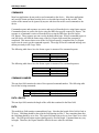
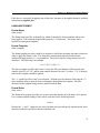
The native resolution of a monitor is the resolution level at which the LCD
panel is designed to perform best. For the Elo LCD touchmonitor, the native
resolution is 1280 x 1024 for the SXGA-17 inch size. In almost all cases, screen
images look best when viewed at their native resolution. You can lower the
resolution setting of a monitor but not increase it.
Input Video
17" LCD
640x480 (VGA)
Transforms input format to 1280x1024
800x600 (SVGA)
1024x768 (XGA)
1280x1024 (SXGA)
Transforms input format to 1280x1024
Transforms input format to 1280x1024
Displays in Native Resolution
The native resolution of an LCD is the actual number of pixels horizontally in
the LCD by the number of pixels vertically in the LCD. LCD resolution is
usually represented by the following symbols:
VGA
640x480
SVGA
800x600
XGA
1024x768
SXGA
1280x1024
UXGA
1600x1200
A-25
As an example, a SVGA resolution LCD panel has 800 pixels horizontally by
600 pixels vertically. Input video is also represented by the same terms. XGA
input video has a format of 1024 pixels horizontally by 768 pixels vertically.
When the input pixels contained in the video input format match the native
resolution of the panel, there is a one to one correspondence of mapping of input
video pixels to LCD pixels. As an example, the pixel in column 45 and row 26
of the input video is in column 45 and row 26 of the LCD. For the case when
the input video is at a lower resolution than the native resolution of the LCD, the
direct correspondence between the video pixels and the LCD pixels is lost. The
LCD controller can compute the correspondence between video pixels and LCD
pixels using algorithms contained on its controller. The accuracy of the
algorithms determines the fidelity of conversion of video pixels to LCD pixels.
Poor fidelity conversion can result in artifacts in the LCD displayed image such
as varying width characters.
A-26
Elo Entuitive Touchmonitor User Guide
APPENDIX
B
TOUCHMONITOR SAFETY
CHAPTER 4
This manual contains information that is important for the proper setup and
maintenance of your touchmonitor. Before setting up and powering on your new
touchmonitor, read through this manual, especially Chapter 2 (Installation), and
Chapter 3 (Operation).
1 To reduce the risk of electric shock, follow all safety notices and never open
the touchmonitor case.
2 Turn off the product before cleaning
3 Your new touchmonitor is equipped with a 3-wire, grounding power cord.
The power cord plug will only fit into a grounded outlet. Do not attempt to fit
the plug into an outlet that has not been configured for this purpose. Do not
use a damaged power cord. Use only the power cord that comes with your
Elo TouchSystems Touchmonitor. Use of an unauthorized power cord may
invalidate your warranty.
4 The slots located on the sides and top of the touchmonitor case are for
ventilation. Do not block or insert anything inside the ventilation slots.
5 It is important that your touchmonitor remains dry. Do not pour liquid into or
onto your touchmonitor. If your touchmonitor becomes wet do not attempt to
repair it yourself.
B-27
Care and Handling of Your Touchmonitor
The following tips will help keep your Elo Entuitive touchmonitor functioning
at the optimal level.
• To avoid risk of electric shock, do not disassemble the brick supply or
display unit cabinet. The unit is not user serviceable. Remember to unplug
the display unit from the power outlet before cleaning.
• Do not use alcohol (methyl, ethyl or isopropyl) or any strong dissolvent. Do
not use thinner or benzene, abrasive cleaners or compressed air.
• To clean the display unit cabinet, use a cloth lightly dampened with a mild
detergent.
• Avoid getting liquids inside your touchmonitor. If liquid does get inside,
have a qualified service technician check it before you power it on again.
• Do not wipe the screen with a cloth or sponge that could scratch the surface.
• To clean the touchscreen, use window or glass cleaner. Put the cleaner on the
rag and wipe the touchscreen. Never apply the cleaner directly on the
touchscreen
B-28
Elo Entuitive Touchmonitor User Guide
APPENDIX
C
TECHNICAL SPECIFICATIONS
CHAPTER0
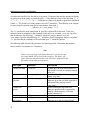
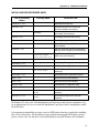
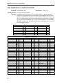
Compatible Video Modes
Your Elo Entuitive touchmonitor is compatible with the following standard
video modes:
Mode
Resolution
H. Frequency (kHz)
V. Frequency (Hz)
IBM & VESA VGA
720 x 400
31.47
70.09
IBM & VESA VGA
IBM & VESA VGA
IBM & VESA VGA
640 x 480
640 x 480
640 x 480
31.47
37.86
37.50
59.94
72.81
75.00
VESA SVGA
VESA SVGA
800 x 600
800 x 600
35.16
37.88
56.25
60.32
VESA SVGA
VESA SVGA
800 x 600
800 x 600
48.08
46.88
72.19
75.00
VESA XGA
VESA XGA
VESA XGA
1024 x 768
1024 x 768
1024 x 768
48.36
56.48
60.02
60.00
70.07
75.03
VESA SXGA
VESA SXGA
1280 x 1024
1280 x 1024
64
80
60
75
VESA SXGA
Apple Macintosh 16”
NEC FC-98 series
1152 x 864
832 x 624
640 x 400
67.5
49.73
24.83
75
74.55
56.42
NEC FC-98 series
NEC FC-98 series
640 x 400
640 x 480
31.47
31.47
70.01
59.94
C-29
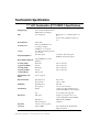
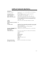
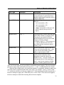
Touchmonitor Specifications
17" LCD Touchmonitor (ET17-XXWF-1) Specifications
Size
Active matrix, thin film transistor
(TFT), liquid crystal display
17-inch diagonal
Pixel Format
1280 x 1024
Touchscreen
0.125-inch IntelliTouch and
AccuTouch, anti-glare
IntelliTouch or AccuTouch
16.7 million with dithering, 6 bits
per color data
250 cd/m² typical
Display Type
Colors
Display Brightness
Horizontal: 13.3” (338mm) useful screen
area
Vertical: 10.6” (270mm) useful screen
area
AccuTouch: 205 cd/m² typical
IntelliTouch: 230 cd/m² typical
Back-light Lamp Life
typical 40,000 hours to half
brightness
Viewing Angle
(typical) (CR=10)
Horizontal
Vertical
±70° or 140° total
±70° or 140° total
Viewing Angle
(typical) (CR=5)
Horizontal
Vertical
±80° or 160° total
±80° or 160° total
Contrast Ratio
450:1 typical
Display Response
Time
16 msec (typical)
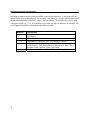
Environmental
Operating Temp
Storage Temp
0°C to 40°C
-20°C to +60°C
Humidity
Operating Temp
Storage Temp
Weight
20%-80%
5%-95% noncondensing
21.6 lbs. (9.82 kg.) maximum approx.
weight for IntelliTouch and AccuTouch
Size
See drawings in this Appendix.
Electrical
Input Video
Speakers
Input Power
Power Dissipation
8 ohms, 1 watt per speaker
Analog (no proprietary video card
needed); Digital Video Input (DVI-D)
100-240 VAC, 50/60 Hz.
45 W max.
Agencies
Safety & EMC
Mechanical
C-30
Elo Entuitive Touchmonitor User Guide
UL, cUL, FCC-B, IC, CE, TÜV-GS,
VCCI, and C-Tick
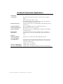
IntelliTouch Touchmonitor Specifications
Mechanical
Positional Accuracy
Touchpoint Density
Touch Activation Force
Surface Durability
Expected Life Performance
Sealing
Standard deviation of error is less than 0.080 in. (2.03 mm). Equates to
less than ±1%.
More than 100,000 touchpoints/in2 (15,500 touchpoints/cm2).
Typically less than 3 ounces (85 grams).
Surface durability is that of glass, Mohs’ hardness rating of 7.
No known wear-out mechanism, as there are no layers, coatings, or
moving parts. IntelliTouch technology has been operationally tested to
more than 50 million touches in one location without failure, using a
stylus similar to a finger.
Unit is sealed to protect against splashed liquids, dirt, and dust.
Optical
Light Transmission (per ASTM
D1003)
Visual Resolution
Gloss (per ASTM D2457 using a
60-degree gloss meter)
Environmental
Chemical Resistance
Electrostatic Protection
(per EN 61 000-4-2, 1995)
90%
All measurements made using USAF 1951 Resolution Chart, under 30X
magnification, with test unit located approximately 1.5 in (38 mm) from
surface of resolution chart.
Clear surface: Excellent, with no noticeable degradation.
Antiglare surface: 6:1 minimum.
Antiglare surface: Curved: 60 ± 20 gloss units or 75 ± 15 gloss units.
The active area of the touchscreen is resistant to all chemicals that do
not affect glass, such as:
Acetone
Toluene
Methyl ethyl ketone
Isopropyl alcohol
Methyl alcohol
Ethyl acetate
Ammonia-based glass cleaners
Gasoline
Kerosene
Vinegar
Meets Level 4 (15 kV air/8 kV contact discharges).
C-31
AccuTouch Touchmonitor Specifications
Mechanical
Construction
Positional Accuracy
Touchpoint Density
Touch Activation Force
Surface Durability
Expected Life
Performance
Top: Polyester with outside hard-surface coating with clear or antiglare
finish.
Inside: Transparent conductive coating.
Bottom: Glass substrate with uniform resistive coating. Top and bottom
layers separated by Elo-patented separator dots.
Standard deviation of error is less than 0.080 in. (2.03 mm). This equates to
less than ±1%.
More than 100,000 touchpoints/in² (15,500 touchpoints/cm²).
Typically less than 4 ounces (113 grams).
Meets Taber Abrasion Test (ASTM D1044), CS-10F wheel, 500 g. Meets
pencil hardness 3H.
AccuTouch technology has been operationally tested to greater than 35
million touches in one location without failure, using a stylus similar to a
finger.
Optical
Light Transmission
(per ASTM D1003)
Visual Resolution
Typically 75% at 550-nm wavelength (visible light spectrum).
Haze (per ASTM D1003)
Gloss (per ASTM D2457)
Antiglare surface: Less than 15%.
C-32
All measurements made using USAF 1951 Resolution Chart, under 30 X
magnification, with test unit located approximately 1.5 in. (38 mm) from
surface of resolution chart.
Antiglare surface: 6:1 minimum.
Antiglare surface: 90 ± 20 gloss units tested on a hard-coated front surface.
Elo Entuitive Touchmonitor User Guide
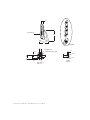
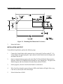
17" LCD Touchmonitor Dimensions
478
434
338
370
270.3
429
219
43
C-33
67.7
See Detail A
279
239
Detail A
100
5X Stability Pad
6.5
23.6
M5 Mounting Holes (4X)
R3.25
10.8
123.2
100
86.6
R6.25
See Detail A
100
Base Bottom
Scale 1:4
C-34
Elo Entuitive Touchmonitor User Guide
Detail A
Scale 1:1
REGULATORY INFORMATION
CHAPTER0
I. Electrical Safety Information:
A) Compliance is required with respect to the voltage, frequency, and current
requirements indicated on the manufacturer’s label. Connection to a different
power source than those specified herein will likely result in improper operation,
damage to the equipment or pose a fire hazard if the limitations are not followed.
B) There are no operator serviceable parts inside this equipment. There are hazardous voltages generated by this equipment which constitute a safety hazard. Service
should be provided only by a qualified service technician.
C) This equipment is provided with a detachable power cord which has an integral
safety ground wire intended for connection to a grounded safety outlet.
1) Do not substitute the cord with other than the provided approved type.
Under no circumstances use an adapter plug to connect to a 2-wire outlet as
this will defeat the continuity of the grounding wire.
2) The equipment requires the use of the ground wire as a part of the safety
certification, modification or misuse can provide a shock hazard that can
result in serious injury or death.
3) Contact a qualified electrician or the manufacturer if there are questions
about the installation prior to connecting the equipment to mains power.
II. Emissions and Immunity Information
A) Notice to Users in the United States: This equipment has been tested and found
to comply with the limits for a Class B digital device, pursuant to Part 15 of FCC
Rules. These limits are designed to provide reasonable protection against harmful
interference in a residential installation. This equipment generates, uses, and can
radiate radio frequency energy, and if not installed and used in accordance with the
instructions, may cause harmful interference to radio communications.
B) Notice to Users in Canada: This equipment complies with the Class B limits for
radio noise emissions from digital apparatus as established by the Radio Interference Regulations of Industrie Canada.
C) Notice to Users in the European Union: Use only the provided power cords and
interconnecting cabling provided with the equipment. Substitution of provided
cords and cabling may compromise electrical safety or CE Mark Certification for
emissions or immunity as required by the following standards:
35
This Information Technology Equipment (ITE) is required to have a CE Mark
on the manufacturer’s label which means that the equipment has been tested
to the following Directives and Standards:
This equipment has been tested to the requirements for the CE Mark as
required by EMC Directive 89/336/EEC indicated in European Standard EN
55 022 Class B and the Low Voltage Directive 73/23/EEC as indicated in
European Standard EN 60 950.
D) General Information to all Users: This equipment generates, uses and can radiate radio frequency energy. If not installed and used according to this manual the
equipment may cause interference with radio and television communications.
There is, however, no guarantee that interference will not occur in any particular
installation due to site-specific factors.
1) In order to meet emission and immunity requirements, the user must
observe the following:
a) Use only the provided I/O cables to connect this digital device with
any computer.
b) To ensure compliance, use only the provided manufacturer’s approved
line cord.
c) The user is cautioned that changes or modifications to the equipment
not expressly approved by the party responsible for compliance could
void the user’s authority to operate the equipment.
2) If this equipment appears to cause interference with radio or television
reception, or any other device:
a) Verify as an emission source by turning the equipment off and on.
b) If you determine that this equipment is causing the interference, try to
correct the interference by using one or more of the following measures:
i) Move the digital device away from the affected receiver.
ii) Reposition (turn) the digital device with respect to the affected
receiver.
iii) Reorient the affected receiver’s antenna.
iv) Plug the digital device into a different AC outlet so the digital
device and the receiver are on different branch circuits.
v) Disconnect and remove any I/O cables that the digital device
does not use. (Unterminated I/O cables are a potential source of
high RF emission levels.)
vi) Plug the digital device into only a grounded outlet receptacle.
Do not use AC adapter plugs. (Removing or cutting the line cord
ground may increase RF emission levels and may also present a
lethal shock hazard to the user.)
If you need additional help, consult your dealer, manufacturer, or an experienced radio or television technician.
36
Elo Entuitive Touchmonitor User Guide
N10051
37
38
Elo Entuitive Touchmonitor User Guide
WARRANTY
CHAPTER0
Except as otherwise stated herein or in an order acknowledgment delivered to
Buyer, Seller warrants to Buyer that the Product shall be free of defects in
materials and workmanship. The warranty for the touchmonitors and
components of the product is 1 year.
Seller makes no warranty regarding the model life of components. Seller’s
suppliers may at any time and from time to time make changes in the
components delivered as Products or components.
Buyer shall notify Seller in writing promptly (and in no case later than thirty
(30) days after discovery) of the failure of any Product to conform to the
warranty set forth above; shall describe in commercially reasonable detail in
such notice the symptoms associated with such failure; and shall provide to
Seller the opportunity to inspect such Products as installed, if possible. The
notice must be received by Seller during the Warranty Period for such product,
unless otherwise directed in writing by the Seller. Within thirty (30) days after
submitting such notice, Buyer shall package the allegedly defective Product in
its original shipping carton(s) or a functional equivalent and shall ship to Seller
at Buyer’s expense and risk.
Within a reasonable time after receipt of the allegedly defective Product and
verification by Seller that the Product fails to meet the warranty set forth above,
Seller shall correct such failure by, at Seller’s options, either (i) modifying or
repairing the Product or (ii) replacing the Product. Such modification, repair, or
replacement and the return shipment of the Product with minimum insurance to
Buyer shall be at Seller’s expense. Buyer shall bear the risk of loss or damage in
transit, and may insure the Product. Buyer shall reimburse Seller for
transportation cost incurred for Product returned but not found by Seller to be
defective. Modification or repair, of Products may, at Seller’s option, take place
either at Seller’s facilities or at Buyer’s premises. If Seller is unable to modify,
repair, or replace a Product to conform to the warranty set forth above, then
Seller shall, at Seller’s option, either refund to Buyer or credit to Buyer’s
account the purchase price of the Product less depreciation calculated on a
straight-line basis over Seller’s stated Warranty Period.
39
THESE REMEDIES SHALL BE THE BUYER’S EXCLUSIVE REMEDIES
FOR BREACH OF WARRANTY. EXCEPT FOR THE EXPRESS
WARRANTY SET FORTH ABOVE, SELLER GRANTS NO OTHER
WARRANTIES, EXPRESS OR IMPLIED BY STATUTE OR OTHERWISE,
REGARDING THE PRODUCTS, THEIR FITNESS FOR ANY PURPOSE,
THEIR QUALITY, THEIR MERCHANTABILITY, THEIR
NONINFRINGEMENT, OR OTHERWISE. NO EMPLOYEE OF SELLER
OR ANY OTHER PARTY IS AUTHORIZED TO MAKE ANY WARRANTY
FOR THE GOODS OTHER THAN THE WARRANTY SET FORTH
HEREIN. SELLER’S LIABILITY UNDER THE WARRANTY SHALL BE
LIMITED TO A REFUND OF THE PURCHASE PRICE OF THE PRODUCT.
IN NO EVENT SHALL SELLER BE LIABLE FOR THE COST OF
PROCUREMENT OR INSTALLATION OF SUBSTITUTE GOODS BY
BUYER OR FOR ANY SPECIAL, CONSEQUENTIAL, INDIRECT, OR
INCIDENTAL DAMAGES.
Buyer assumes the risk and agrees to indemnify Seller against and hold Seller
harmless from all liability relating to (i) assessing the suitability for Buyer’s
intended use of the Products and of any system design or drawing and (ii)
determining the compliance of Buyer’s use of the Products with applicable
laws, regulations, codes, and standards. Buyer retains and accepts full
responsibility for all warranty and other claims relating to or arising from
Buyer’s products, which include or incorporate Products or components
manufactured or supplied by Seller. Buyer is solely responsible for any and all
representations and warranties regarding the Products made or authorized by
Buyer. Buyer will indemnify Seller and hold Seller harmless from any liability,
claims, loss, cost, or expenses (including reasonable attorney’s fees) attributable
to Buyer’s products or representations or warranties concerning same.
40
Elo Entuitive Touchmonitor User Guide
Index
Numerics
17" LCD Touchmonitor (ET17-XXWF-1) Specifications, 30
17" LCD Touchmonitor Dimensions, 33
Expected Life Performance, AccuTouch, 32
Expected Life Performance, IntelliTouch, 31
G
A
About the Product, 1
About Touchmonitor Adjustments, 19
Accessing the VESA Mounting Interface, 14
AccuTouch Touchmonitor Specifications, 32
Agencies, 30
Auto Adjust, 21
GCX, 14
Gloss, AccuTouch, 32
Gloss, IntelliTouch, 31
H
Haze, AccuTouch, 32
H-Position, 21
Humidity, 30
B
Back-light Lamp Life, 30
Base Bottom View, 5
Brightness, 21
C
C1/C2/USER (Color), 21
Care and Handling of Your Touchmonitor, 28
Chemical Resistance, IntelliTouch, 31
Cleaning Your Touchmonitor, 28
Clock, 21
Colors, 30
Compatible Video Modes, 29
Connecting the Power Cable, 12
Connecting the Serial or USB Touchscreen Cable, 10
Connecting the Speaker Cable, 11
Connecting the Video Cable or DVI-D Video Cable, 9
Construction, AccuTouch, 32
Contrast, 20, 21
Contrast Ratio, 30
I
Image Information, 21
Image problem, 23
Image, scrolling, 24
Image, unstable, 24
Image, vertical flickering, 24
Innovative Office Products, 14
Installation and Setup, 3
Installing the Driver Software, 15
Installing the Serial Touch Driver for MS-DOS and
Windows 3.1, 17
Installing the Serial Touch Driver for Windows XP,
Windows 2000, Me, 95/98 and NT 4.0, 16
Installing the USB Touch Driver, 18
Installing the USB Touch Driver for Windows XP, Windows
2000, Me and 98, 18
IntelliTouch Touchmonitor Specifications, 31
Introduction, 1
L
D
Display Brightness, 30
Display Response Time, 30
Display Type, 30
E
Electrical, 30
Electrical Safety Information, 35
Electrostatic Protection, IntelliTouch, 31
Emissions and Immunity Information, 35
Enable/Disable, 20
Environmental, 30, 31
Ergotron, 14
Light Transmission, AccuTouch, 32
Light Transmission, IntelliTouch, 31
M
Main Unit, 4
Mechanical, 30
Mechanical, AccuTouch, 32
Mechanical, IntelliTouch, 31
Menu, 20
Minus Counter-clockwise, 20
Mounting the Base, 14
MRI, 14
Index-41
N
Native Resolution, 25
O
Operation, 19
Optical, AccuTouch, 32
Optical, IntelliTouch, 31
Optimizing the LCD Display, 13
OSD H-Position, 21
OSD Language, 21
OSD Menu Function, 21
OSD Time, 21
OSD V-Position, 21
Out of Range display, 23
P
Phase, 21
Pixel Format, 30
Plus/Clockwise, 20
Positional Accuracy, AccuTouch, 32
Positional Accuracy, IntelliTouch, 31
Power Switch, 20
Precautions, 1
Product Overview, 4
R
Rear View, 4
Recall Defaults, 21
Regulatory Information, 35
Removing the Back Cover, 7
Replacing the Back Cover, 12
Routing the Cables, 8
S
Sealing, IntelliTouch, 31
Serial or USB Connection, 6
Side Bezel Buttons, 20
Side View, 5
Solutions to Common Problems, 23
Speakers, 30
Surface Durability, AccuTouch, 32
Surface Durability, IntelliTouch, 31
SVGA, 25
SXGA, 25
T
Technical Specifications, 29
Touch Activation Force, AccuTouch, 32
Touch Activation Force, IntelliTouch, 31
Touch Interface Connection, 6
Touch not working, 24
Touchmonitor Safety, 27
Touchmonitor Specifications, 30
Touchpoint Density, AccuTouch, 32
Touchpoint Density, IntelliTouch, 31
Touchscreen, 30
Troubleshooting, 23
U
Unpacking Your Touchmonitor, 3
Using the On-Screen Display (OSD) Menus, 19
UXGA, 25
V
VESA Mount on Your Touchmonitor, 13
VGA, 25
Viewing Angle (typical) (CR=10), 30
Viewing Angle (typical) (CR=5), 30
Visual Resolution, AccuTouch, 32
Visual Resolution, IntelliTouch, 31
Volume, 20
V-Position, 21
W
Warranty, 39
X
XGA, 25
Index-42
PORT POWERED
SWIPE READER
TECHNICAL REFERENCE MANUAL
Manual Part Number 99875094 Rev 10
JULY 2001
20725 South Annalee Avenue
Carson, CA 90746
Phone: (310) 631-8602
FAX: (310) 631-3956
Technical Support: (888) 624-8350
www.magtek.com
Copyright 1997-2001
MAG-TEK, Inc.
Printed in the United States of America
Information in this document is subject to change without notice. No part of this document may
be reproduced or transmitted in any form or by any means, electronic or mechanical, for any
purpose, without the express written permission of Mag-Tek, Inc.
Mag-Tek is a registered trademark of Mag-Tek, Inc.
Procomm is a registered trademark of Datastorm Technologies, Inc.
REVISIONS
ii
Rev Number
1
2
Date
11 Dec 97
18 Dec 97
3
11 May 98
4
5
15 Jun 98
1 Mar 99
6
14 Jun 99
7
1 Dec 99
8
21 Sep 00
9
09 Mar 01
10
25 Jul 01
Notes
Initial Release
Sec 1 Changed spec Dimensions; Sec 1, 3 Changed illustrations
for clarity.
Sections 1, 2, and 3 revised to reflect latest firmware revisions.
Sec 4 deleted.
Two part numbers added.
Sec 1, Added 3 part numbers, changed specs, Changed
Dimensions Figure 1-3, removed Figure 1-4, Mounting
Dimensions, added Mag-Tek Windows Drivers; Added note to
Table 1-1.
Section 2, added mounting instructions and Figure 2-1, Mounting
Dimensions. Section 3, added 3 track symbols to Table 3-1 and
3 sign-on configurations to 3-2.
Title change, Removed MT-211 and RS-232; Sec 1, Table 1-1,
added Pin List for Cable 21040077, added RS-232
Communication; Sec 2, added Demo Program from Net; Sec 3,
Clarified Fig 3-1, Described firmware P/Ns and revisions.
Section 1: Added P/N 21040084, Updated table for 9- and 25-pin
connectors; Section 3: Added P/N 21040084 to Sign-on table.
Editorial changes throughout. Sec 1: Configuration list expanded
and moved to Sec 3; Specification weight changed from 5.9 oz to
5.8oz, Converted symbols to Metric System [SI]. Sec 3: Added 5
new part numbers with firmware, tracks, and configurations.
Front Matter: Corrected Agency Approvals to include
Class B for FCC and Class B for CE. Changed RMA Warranty
address to 20801 S. Annalee. Section 3: Removed “Track 3 – 7
bit” line from Table 3-1. Added 094 and 096 configurations in
Table 3-2.
Front Matter: Agency Approvals: Corrected Class B for CE and
Corrected UL and CUL . Copyright 2001 added.
Limited Warranty
Mag-Tek, Inc. (hereinafter “Mag-Tek”) warrants this Mag-Tek product IN ITS ENTIRETY, to
be in good working order for a period of one year from the date of purchase from Mag-Tek.
Should this product fail to be in good working order at any time during this warranty period,
Mag-Tek will, at its option, repair or replace this product at no additional charge except as set
forth below. Repair parts and replacement products will be furnished on an exchange basis and
will be either reconditioned or new. All replaced parts and products become the property of
Mag-Tek. This limited warranty does not include service to repair damage to the product
resulting from accident, disaster, misuse, abuse, or non-Mag-Tek modification of the product.
Limited Warranty service may be obtained by delivering the product during the warranty period
to Mag-Tek (20801 S. Annalee Ave., Carson, CA 90746). If this product is delivered by mail,
you agree to insure the product or assume the risk of loss or damage in transit, to prepay shipping
charges to the warranty service location and to use the original shipping container or equivalent.
ALL EXPRESS AND IMPLIED WARRANTIES FOR THIS PRODUCT, INCLUDING THE
WARRANTIES OF MERCHANTABILITY AND FITNESS FOR A PARTICULAR
PURPOSE, ARE LIMITED IN DURATION TO A PERIOD OF ONE YEAR FROM THE
DATE OF PURCHASE, AND NO WARRANTIES, WHETHER EXPRESS OR IMPLIED,
WILL APPLY AFTER THIS PERIOD, EXCEPT AS PROVIDED IN THE PRECEDING
SENTENCE. EACH PURCHASER UNDERSTANDS THAT THE MAG-TEK PRODUCT IS
OFFERED AS IS.
IF THIS PRODUCT IS NOT IN GOOD WORKING ORDER AS WARRANTED ABOVE,
YOUR SOLE REMEDY SHALL BE REPAIR OR REPLACEMENT AS PROVIDED ABOVE.
IN NO EVENT WILL MAG-TEK BE LIABLE TO YOU FOR ANY DAMAGES,
INCLUDING ANY LOST PROFITS, LOST SAVINGS OR OTHER INCIDENTAL OR
CONSEQUENTIAL DAMAGES ARISING OUT OF THE USE OF OR INABILITY TO USE
SUCH PRODUCT, EVEN IF MAG-TEK HAS BEEN ADVISED OF THE POSSIBILITY OF
SUCH DAMAGES, OR FOR ANY CLAIM BY ANY OTHER PARTY.
THIS WARRANTY GIVES YOU SPECIFIC LEGAL RIGHTS, AND YOU MAY ALSO
HAVE OTHER RIGHTS WHICH VARY FROM STATE TO STATE.
iii
FCC WARNING STATEMENT
This equipment has been tested and found to comply with the limits for Class B digital device, pursuant to
Part 15 of FCC Rules. These limits are designed to provide reasonable protection against harmful
interference when the equipment is operated in a residential environment. This equipment generates,
uses, and can radiate radio frequency energy and, if not installed and used in accordance with the
instruction manual, may cause harmful interference to radio communications. However, there is no
guarantee that interference will not occur in a particular installation.
FCC COMPLIANCE STATEMENT
This device complies with Part 15 of the FCC Rules. Operation of this device is subject to the following
two conditions: (1) This device may not cause harmful interference; and (2) this device must accept any
interference received, including interference that may cause undesired operation.
CANADIAN DOC STATEMENT
This digital apparatus does not exceed the Class B limits for radio noise for digital apparatus set out in the
Radio Interference Regulations of the Canadian Department of Communications.
Le présent appareil numérique n’émet pas de bruits radioélectriques dépassant les limites applicables
aux appareils numériques de las classe B prescrites dans le Réglement sur le brouillage radioélectrique
édicté par les ministère des Communications du Canada.
CE STANDARDS
Testing for compliance to CE and FCC requirements was performed by an independent laboratory. The
unit under test was found compliant to Class B.
UL/CSA
This product is recognized per Underwriter Laboratories and Canadian Underwriter Laboratories 1950.
iv
TABLE OF CONTENTS
SECTION 1. FEATURES AND SPECIFICATIONS --------------------------------------------------------------------- 1
MAG-TEK DEVICE DRIVERS FOR WINDOWS ---------------------------------------------------------------------- 1
FEATURES --------------------------------------------------------------------------------------------------------------------- 1
CONFIGURATION------------------------------------------------------------------------------------------------------------ 2
SPECIFICATIONS ------------------------------------------------------------------------------------------------------------ 3
SECTION 2. INSTALLATION ------------------------------------------------------------------------------------------------ 5
REQUIREMENTS------------------------------------------------------------------------------------------------------------- 5
MOUNTING--------------------------------------------------------------------------------------------------------------------- 5
INSTALLATION AND TEST ------------------------------------------------------------------------------------------------ 6
SECTION 3. OPERATION ----------------------------------------------------------------------------------------------------- 9
LED INDICATOR-------------------------------------------------------------------------------------------------------------- 9
CARD READ ------------------------------------------------------------------------------------------------------------------- 9
READER TO HOST MESSAGE FORMAT ----------------------------------------------------------------------------- 9
TIMING FOR ID SIGN ON -------------------------------------------------------------------------------------------------10
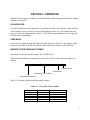
FIGURES
Figure 1-1.
Figure 1-2.
Figure 1-3.
Figure 2-1.
Figure 3-1.
Port-Powered Swipe Reader----------------------------------------------------------------------------------- vi
Reader Cable and Optional Adapter ------------------------------------------------------------------------- 2
Dimensions --------------------------------------------------------------------------------------------------------- 4
Mounting Hole Dimensions For Surface -------------------------------------------------------------------- 6
Timing For ID Sign-on and Transmission Bursts. --------------------------------------------------------10
TABLES
Table 1-1.
Table 1-2.
Table 3-1.
Table 3-2.
OEM and 9-Pin Connectors and 25-Pin Adapter ---------------------------------------------------------- 2
Specifications ------------------------------------------------------------------------------------------------------- 3
SS and ES Track Symbols -------------------------------------------------------------------------------------- 9
Sign-on ID for Configurations ----------------------------------------------------------------------------------11
v
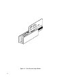
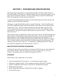
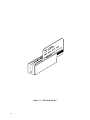
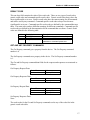
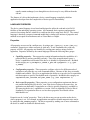
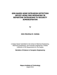
Figure 1-1. Port-Powered Swipe Reader
vi
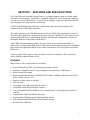
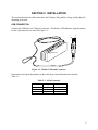
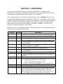
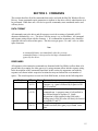
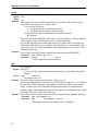
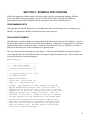
SECTION 1. FEATURES AND SPECIFICATIONS
The Port Powered Swipe Reader is a compact magnetic stripe card reader which conforms to
ISO/ANSI standards. The Reader is compatible with the PC series of personal computers or any
device with a serial RS-232 interface. A card is read by sliding it, stripe down and facing the
LED side, through the slot either forward or backward.
A green LED (Light Emitting Diode) indicator on the Reader panel provides the operator with
continuous status of the Reader operations.
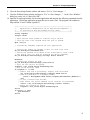
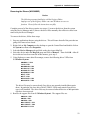
When power is applied, the Reader transmits a sign-on ID message. About 150 milliseconds
after DTR is applied, the Reader sends the part number of the firmware in the following form:
21088819A01 <CR>. The first 8 characters indicate the firmware number; the letter is the
revision, which is followed by a revision sublevel of 01 to 99. The <CR> indicates carriage
return (0x0D). The sign-on messages for part numbers are listed in Section 3. Timing is also
shown in Section 3.
Since the input voltage is supplied by a relatively low source of power, the Reader depends on its
input capacitor to maintain proper charge during all operations. In order to reduce the drain on
this internal power source during data transmission, the output data is transmitted in 5 to 6
millisecond bursts with a 10-millisecond gap between bursts to allow the capacitor to recharge.
The PC software should be able to tolerate this 10-millisecond space between characters. The
Timing is shown is Section 3, Figure 3-1. Configurations, including part numbers, firmware,
tracks, and unit configuration, are listed in Section 3, Table 3-2.
MAG-TEK DEVICE DRIVERS FOR WINDOWS
The Mag-Tek Device Drivers for Windows, Part Number 30037385, may be used with the Port
Powered Swipe Reader. When this program is used, refer to Mag-Tek Device Driver for
Windows, Programming Reference Manual, Part Number 99875125.
FEATURES
Major features of the Swipe Reader are as follows:
•
•
•
•
•
•
Powered through the RS-232 serial port – no external power supply required
Hardware Compatible with PC or any computer or terminal with an RS-232 interface
Software Compatible with Procomm, or any RS-232 communications program
Bidirectional card reading
Reads encoded data that meets ANSI/ISO/CDL/AAMVA standards
Green LED for status
1
Port Powered Swipe Reader
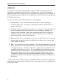
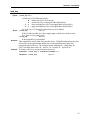
CONFIGURATION
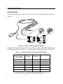
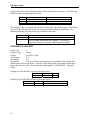
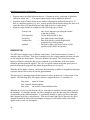
The Reader, LED Indicator, pin numbers for the 9-pin connector, and the Adapter are shown in
Figure 1-2.
Figure 1-2. Reader Cable and Optional Adapter
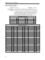
Pin numbers and signal descriptions for the 9-pin (DE9) cable and 25-pin (DB25) adapter shown
in the illustration are listed in Table 1-1. Also listed is the pin list OEM version, P/N 21040077.
Table 1-1. OEM and 9-Pin Connectors and 25-Pin Adapter
25-pin
Adapter
DE9-pin
Connector
-
1
NC*
1
3
2
RXD (to PC)
2
2
3
TXD** (from PC)
3
20
4
DTR (from PC)
4
7
5
GND
-
6-9
NC*
Connector for OEM
Version 21040077
Signal
J2 on the PCB
* No Connection
** Pin must be connected to TXD (or DTR if TXD not available).
2
Section 1. Features and Specifications
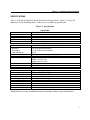
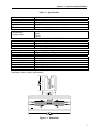
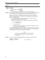
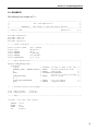
SPECIFICATIONS
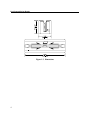
Table 1-2 lists the specifications for the Port Powered Swipe Reader. Figure 1-3 shows the
dimensions for the standard product. Other sizes are available by special order.
Table 1-2. Specifications
Reference Standards
Power Input
Recording Method
Message Format
Card Speed
MTBF
DTR Voltage
Current
Quiescent
Transmitting
Peak at Power On
RS-232 Communication
Dimensions
Weight
Cable length
Connector
Temperature
Operating
Storage
Humidity
Operating
Storage
Altitude
Operating
Storage
OPERATING
ISO/ANSI/ CDL/ AAMVA*
From RS-232 interface
Two-frequency coherent phase (F2F)
ASCII
3 to 50 IPS
Electronics: 125,000 hours. Head: 1,000,000 passes
ELECTRICAL
5 to 15 VDC
1 to 2 mA typical (continuous)
8 to 9 mA typical (5 ms duration)
12 mA
9600 bps, no parity, 8 data bits, 1 stop bit
MECHANICAL (STANDARD PRODUCT)
Length: 3.94” (100.0 mm),
Width: 1.28” (32.5 mm)
Height: 1.23” (31.3 mm)
Reader 5.8 oz. (165 gr.)
5 Ft. (1.5 m)
9 pin D female (May require a 25-pin adapter)
ENVIRONMENTAL
o
o
o
o
32 F to 131 F (0 C to 55 C)
o
o
o
o
-22 F to 158 F (-30 C to 70 C)
10% to 90% noncondensing
Up to 100% noncondensing
0-10,000 ft. (0-3048 m.)
0-50,000 ft. (0-15240 m.)
* ISO (International Standards Organization), ANSI (American National Standards Institute), CDL
(California Drivers License), and AAMVA (American Association of Motor Vehicle Administrators).
3
Port Powered Swipe Reader
Figure 1-3. Dimensions
4
SECTION 2. INSTALLATION
The hardware installation consists of plugging the cable into the PC and optional adapter, if
required, Com Port setup, and testing the Reader.
REQUIREMENTS
•
•
•
•
Port Powered Swipe Reader
Optional 9- to 25-pin Adapter, P/N 78200018
PC with Com Port
Procomm, Hyper Terminal, Mag-Tek Windows Drivers, or other RS-232 communications
program
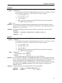
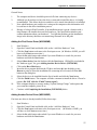
MOUNTING
1.
The Reader can be mounted on a surface in three ways:
• By two screws through the surface attached to the bottom of the unit and running the
cable on the top of the surface;
• By two screws through the surface attached to the bottom of the unit and by drilling a
hole in the surface for the cable and running the cable through the hole;
• By attaching the unit to the surface with fastening tape and running the cable on the top
of the surface.
Note
The two mounting inserts are 3 mm diameter; 0.5 mm pitch; 6.4
mm deep. The length of the screws used depends on the mounting
surface thickness and the thickness of washers (if used).
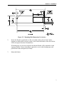
The mounting dimensions are shown in Figure 2-1. Determine the method of mounting
required.
2.
Ensure the Reader is positioned on a flat, accessible surface with at least 4 inches
clearance on either end for room to swipe a card. Orient the Reader so the side with the
LED is facing the direction of intended use.
If fastening tape is to be used, clean the area that the Reader will be mounted on with
isopropyl alcohol. Remove the adhesive protective cover on the fastening tape, and
position the Reader and push down firmly.
5
Port Powered Swipe Reader
Figure 2-1. Mounting Hole Dimensions For Surface
3.
Mount the Reader.
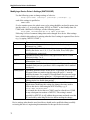
INSTALLATION AND TEST
To install the Swipe Reader, perform the following steps:
1.
Connect the Swipe Reader cable connector into a 9-pin serial Com Port on the PC. If a
25-pin Adapter is required, plug the 9-pin connector on the Reader into the Adapter, and
the adapter into the PC.
2.
Open a communications program such as the Mag-Tek Encoder/Reader Demonstration
Program, which may be obtained from the Internet at www.magtek.com. Navigate to the
Demo Programs and select Reader & Encoder Demos (Win 95/98/NT).
3.
On the program, select the Com Port the Reader is connected to.
4.
If the Com Port selected is correct, the green LED on the Reader will light; if the wrong
Com Port is selected, the LED will not light.
5.
Select the baud rate of 9600.
Section 2. Installation
6.
Select 8 data bits, no parity, 1 stop bit.
7.
With the LED on, swipe a card. The data on the screen will show Track 1 beginning with
“%” and ending with “?”. Track 2 begins with “;” and ends with “?”. Track 3 begins
with “+” (normal) or "!" (CDL) and ends with “?”. The following is an example:
%B123^Smith/Joann^9812101000?;112222333333444444444?<0x0D>
If a track cannot be read, an E will appear in place of the track data; for example, if
Track 2 is bad and Tracks 1 and 3 are good, the display will be similar to the following:
%11111111111111111111?;E?+3333333333333333333?<0x0D>
If Tracks 1 and 3 are bad and Track 2 is good, the display will be similar to the following:
%E?;22222222222222222222?+E?<0x0D>
8.
If the data on the screen is not numeric or alphanumeric similar to the above, check the
communications rate. If the alphanumeric characters are similar to the above, the unit is
ready for operation.
7
Port Powered Swipe Reader
8
SECTION 3. OPERATION
Included in this section are Indicator, Card Read, Reader to Host Message Format, and a timing
diagram of sign-on ID.
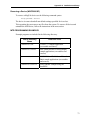
LED INDICATOR
A green LED indicator on the panel gives the operator the status of the Reader. If the cabling is
correct and the correct Com Port is selected, the indicator will be on. If the indictor does not
come on, check the cabling and the Com Port. The LED is turned off during a card swipe and
while the unit is transmitting.
CARD READ
A card may be swiped through the Reader slot when the green LED is lit. The magnetic stripe
must face toward the front (the side with the LED) and may be swiped in either direction.
READER TO HOST MESSAGE FORMAT
Track data is sent in the following order: SS, Card Data, ES.
The format in which data is transmitted (in track order) after a card is read successfully is as
follows:
SS
CARD DATA
ES
CR
Carriage Return
End Sentinel
Card Data or "E" (for Error)
Start Sentinel Character
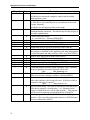
Table 3-1 lists Start Sentinel and End Sentinel symbols.
Table 3-1. SS and ES Track Symbols
Start Sentinel
%
;
+
#
!
End Sentinel
?
?
?
?
?
Description
Track 1
Track 2
Track 3 - ISO
Track 3 - AAMVA
Track 3 - CDL
9
Port Powered Swipe Reader
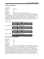
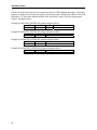
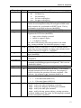
TIMING FOR ID SIGN ON
Timing for the ID Sign-on and transmission bursts (5 ms with 10 ms between bursts) are shown
in Figure 3-1.
DTR
150 ms
Sign-on ID
Transmission
Burst
5 ms
10 ms
Figure 3-1. Timing For ID Sign-on and Transmission Bursts.
The firmware controls the operation of Sign-on ID and Transmission bursts in the following
format:
210888xxLnn <CR>
Where:
the first 8 digits are the firmware part number (xx represents the Swipe Reader series),
L is the alpha revision,
nn is the number sub-revision.
<CR> is 0x0D.
10
Section 3. Operation
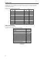
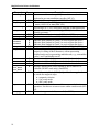
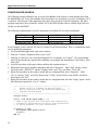
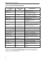
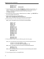
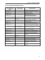
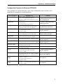
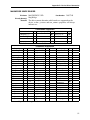
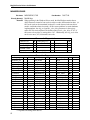
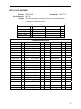
Table 3-2 lists the available part number, firmware, and configuration.
Table 3-2. Sign-on ID for Configurations
Part Number
21040071
21040073
21040074
21040075
21040077
21040079
21040080
21040081
21040082
21040084
Firmware
21088811
21088812
21088817
21088814
21088817
21088811
21088814
21088811
21088817
21088811
Track Configuration
1,2
2,3
1,2,3
2
1,2,3
1,2
2
1,2
1,2,3
1,2
21040086
21040088
21040089
21040091
21040092
21040094
21040096
21088817
21088824
21088811
21088811
21088817
21068811
21088811
1,2,3
1,2,3
1,2
1,2
1,2,3
1,2
1,2
Configuration*
Pearl White
Pearl White
Pearl White
Pearl White
Black, No Cover, No Cable
Black
Black
Black (150 mm)
Black
Pearl White
(with STX and ETX)
Pearl White, No Cover, 12" Cable, 6-pin
Pearl White, 4800/7O, 10' cable
Pearl White, 10' cable
Black, No Cover, 5.9" Cable, 4-pin
Pearl White, 5 m cable
Pearl White, No Cover
Black, 4” Cable, 4-pin
*All cables are 6' DE9 unless otherwise specified.
11
USB (UNIVERSAL SERIAL BUS)
SWIPE READER
TECHNICAL REFERENCE MANUAL
Manual Part Number 99875191 Rev 4
AUGUST 2001
20725 South Annalee Avenue
Carson, CA 90746
Phone: (310) 631-8602
FAX: (310) 631-3956
Technical Support: (888) 624-8350
www.magtek.com
Copyright 2001
MAG-TEK, Inc.
Printed in the United States of America
Information in this document is subject to change without notice. No part of this document may
be reproduced or transmitted in any form or by any means, electronic or mechanical, for any
purpose, without the express written permission of Mag-Tek, Inc.
Mag-Tek is a registered trademark of Mag-Tek, Inc.
USB (Universal Serial Bus) Specification is Copyright¤ 1998 by Compaq Computer
Corporation, Intel Corporation, Microsoft Corporation, NEC Corporation.
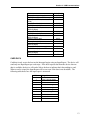
REVISIONS
ii
Rev Number
1
2
Date
15 Jun 01
22 Jun 01
3
25 Jul 01
4
17 Aug 01
Notes
Initial Release
Section 4. On Tracks 1, 2, and 3 Decode
Status delete “more than eight bits of data”
and add “data on it that is not noise.” From
Card Encode Type, Value 3, delete “This
device does not detect blank cards so this
value will never occur.”
Front Matter: Agency Approvals: Corrected
Class B for CE.
Section 4, Report Descriptor: Changed
Logical Maximum from 25 ff to 26 ff 00.
Limited Warranty
Mag-Tek, Inc. (hereinafter “Mag-Tek”) warrants this Mag-Tek product IN ITS ENTIRETY, to
be in good working order for a period of one year from the date of purchase from Mag-Tek.
Should this product fail to be in good working order at any time during this warranty period,
Mag-Tek will, at its option, repair or replace this product at no additional charge except as set
forth below. Repair parts and replacement products will be furnished on an exchange basis and
will be either reconditioned or new. All replaced parts and products become the property of
Mag-Tek. This limited warranty does not include service to repair damage to the product
resulting from accident, disaster, misuse, abuse, or non-Mag-Tek modification of the product.
Limited Warranty service may be obtained by delivering the product during the warranty period
to Mag-Tek (20801 S. Annalee Ave., Carson, CA 90746). If this product is delivered by mail,
you agree to insure the product or assume the risk of loss or damage in transit, to prepay shipping
charges to the warranty service location and to use the original shipping container or equivalent.
ALL EXPRESS AND IMPLIED WARRANTIES FOR THIS PRODUCT, INCLUDING THE
WARRANTIES OF MERCHANTABILITY AND FITNESS FOR A PARTICULAR
PURPOSE, ARE LIMITED IN DURATION TO A PERIOD OF ONE YEAR FROM THE
DATE OF PURCHASE, AND NO WARRANTIES, WHETHER EXPRESS OR IMPLIED,
WILL APPLY AFTER THIS PERIOD, EXCEPT AS PROVIDED IN THE PRECEDING
SENTENCE. EACH PURCHASER UNDERSTANDS THAT THE MAG-TEK PRODUCT IS
OFFERED AS IS.
IF THIS PRODUCT IS NOT IN GOOD WORKING ORDER AS WARRANTED ABOVE,
YOUR SOLE REMEDY SHALL BE REPAIR OR REPLACEMENT AS PROVIDED ABOVE.
IN NO EVENT WILL MAG-TEK BE LIABLE TO YOU FOR ANY DAMAGES,
INCLUDING ANY LOST PROFITS, LOST SAVINGS OR OTHER INCIDENTAL OR
CONSEQUENTIAL DAMAGES ARISING OUT OF THE USE OF OR INABILITY TO USE
SUCH PRODUCT, EVEN IF MAG-TEK HAS BEEN ADVISED OF THE POSSIBILITY OF
SUCH DAMAGES, OR FOR ANY CLAIM BY ANY OTHER PARTY.
THIS WARRANTY GIVES YOU SPECIFIC LEGAL RIGHTS, AND YOU MAY ALSO
HAVE OTHER RIGHTS WHICH VARY FROM STATE TO STATE.
iii
FCC WARNING STATEMENT
This equipment has been tested and found to comply with the limits for Class B digital device, pursuant to
Part 15 of FCC Rules. These limits are designed to provide reasonable protection against harmful
interference when the equipment is operated in a residential environment. This equipment generates,
uses, and can radiate radio frequency energy and, if not installed and used in accordance with the
instruction manual, may cause harmful interference to radio communications. However, there is no
guarantee that interference will not occur in a particular installation.
FCC COMPLIANCE STATEMENT
This device complies with Part 15 of the FCC Rules. Operation of this device is subject to the following
two conditions: (1) This device may not cause harmful interference; and (2) this device must accept any
interference received, including interference that may cause undesired operation.
CANADIAN DOC STATEMENT
This digital apparatus does not exceed the Class B limits for radio noise for digital apparatus set out in the
Radio Interference Regulations of the Canadian Department of Communications.
Le présent appareil numérique n’émet pas de bruits radioélectriques dépassant les limites applicables aux
appareils numériques de las classe B prescrites dans le Réglement sur le brouillage radioélectrique édicté
par les ministère des Communications du Canada.
CE STANDARDS
Testing for compliance to CE requirements was performed by an independent laboratory. The unit under
test was found compliant to Class B.
UL/CSA
This product is recognized per Underwriter Laboratories and Canadian Underwriter Laboratories 1950.
iv
TABLE OF CONTENTS
SECTION 1. FEATURES AND SPECIFICATIONS.....................................................................................1
FEATURES ...............................................................................................................................................1
CONFIGURATIONS..................................................................................................................................2
ACCESSORIES ........................................................................................................................................2
REFERENCE DOCUMENTS....................................................................................................................2
SPECIFICATIONS ....................................................................................................................................2
SECTION 2. INSTALLATION ......................................................................................................................5
USB CONNECTION..................................................................................................................................5
WINDOWS PLUG AND PLAY SETUP .....................................................................................................6
MOUNTING...............................................................................................................................................6
SECTION 3. OPERATION ...........................................................................................................................9
LED INDICATOR ......................................................................................................................................9
CARD READ .............................................................................................................................................9
SECTION 4. USB COMMUNICATIONS .....................................................................................................11
HID USAGES ..........................................................................................................................................11
REPORT DESCRIPTOR.........................................................................................................................12
CARD DATA ...........................................................................................................................................13
TRACK 1 DECODE STATUS .................................................................................................................14
TRACK 2 DECODE STATUS .................................................................................................................14
TRACK 3 DECODE STATUS .................................................................................................................14
TRACK 1 DATA LENGTH.......................................................................................................................14
TRACK 2 DATA LENGTH.......................................................................................................................14
TRACK 3 DATA LENGTH.......................................................................................................................14
CARD ENCODE TYPE ...........................................................................................................................15
TRACK DATA .........................................................................................................................................15
TRACK 1 DATA ......................................................................................................................................15
TRACK 2 DATA ......................................................................................................................................15
TRACK 3 DATA ......................................................................................................................................15
COMMANDS ...........................................................................................................................................16
COMMAND NUMBER.............................................................................................................................16
DATA LENGTH .......................................................................................................................................16
DATA.......................................................................................................................................................16
RESULT CODE.......................................................................................................................................17
GET AND SET PROPERTY COMMANDS.............................................................................................17
SOFTWARE_ID PROPERTY .................................................................................................................18
SERIAL_NUM PROPERTY ....................................................................................................................19
POLLING_INTERVAL PROPERTY ........................................................................................................19
SECTION 5. DEMO PROGRAM .................................................................................................................21
INSTALLATION.......................................................................................................................................21
OPERATION ...........................................................................................................................................21
SOURCE CODE .....................................................................................................................................22
FIGURES
Figure 1-1. USB Swipe Reader----------------------------------------------------------------------------------------------- vi
Figure 1-2. Dimensions --------------------------------------------------------------------------------------------------------- 3
Figure 2-1. Reader Cable and Connector---------------------------------------------------------------------------------- 5
Figure 2-2. Mounting Hole Dimensions For Surface -------------------------------------------------------------------- 7
TABLES
Table 1-2. Specifications ------------------------------------------------------------------------------------------------------- 3
Table 2-1. 4-Pin Connector ---------------------------------------------------------------------------------------------------- 5
v
Figure 1-1. USB Swipe Reader
vi
SECTION 1. FEATURES AND SPECIFICATIONS
The USB (Universal Serial Bus) Swipe Reader is a compact magnetic stripe card reader which
conforms to ISO standards. The Reader is compatible with the PC series of personal computers
or any device with a USB interface. A card is read by sliding it, stripe down and facing the LED
side, through the slot either forward or backward.
A LED (Light Emitting Diode) indicator on the Reader panel provides the operator with
continuous status of the Reader operations.
The reader conforms to the USB Human Interface Device (HID) Class specification Version 1.1.
This allows host applications designed for the latest versions of Windows 98, Me, 2000 to easily
communicate to the device using standard Windows API calls that communicate to the device
through the HID driver that comes with Windows.
Unlike HID keyboard emulation readers, this device does not use keyboard emulation. It
behaves like a vendor defined HID device so that a direct communication path can be established
between the Host application and the device without interference such as keystrokes from other
HID devices.
A demo program with its source code is available, written in Visual Basic, that exercises the
device using the standard Windows API.
FEATURES
Major features of the Swipe Reader are as follows:
•
•
•
•
•
•
•
•
•
•
•
•
•
Powered through the USB – no external power supply required
Hardware Compatible with PC or any computer or terminal with a USB interface
Bi-directional card reading
Reads encoded data that meets ANSI/ISO/CDL/AAMVA standards and others such as ISO
track 1 format on track 2 or 3.
Reads up to three tracks of card data
LED for status
Compatible with USB specification Revision 1.1
Compatible with HID specification Version 1.1
Can use standard Windows HID driver for communications. No third part device driver is
required.
Programmable USB serial number descriptor
Programmable USB Interrupt In Endpoint polling interval
Non-volatile flash EEPROM memory for property storage
Built-in 6 foot USB cable
1
USB Swipe Reader
CONFIGURATIONS
The Configurations are as follows:
Part Number
P/N 21040101
P/N 21040102
P/N 21040103
P/N 21040104
P/N 21040105
P/N 21040106
Tracks
TK 1,2,3
TK 1,2,3
TK 1,2
TK 1,2
TK 2
TK 2
Color
Pearl White
Black
Pearl White
Black
Pearl White
Black
ACCESSORIES
The accessories are as follows:
Part Number
21042806
99510026
Description
USB MSR Demo Program with Source Code (Diskette)
USB MSR Demo Program with Source Code (WEB)
REFERENCE DOCUMENTS
Axelson, Jan. USB Complete, Everything You Need to Develop Custom USB Peripherals, 1999.
Lakeview Research, 2209 Winnebago St., Madison WI 53704, 396pp., http://www.lvr.com.
USB Human Interface Device (HID) Class Specification Version 1.1.
USB (Universal Serial Bus) Specification, Version 1.1, Copyright¤ 1998 by Compaq Computer
Corporation, Intel Corporation, Microsoft Corporation, NEC Corporation.
USB Implementers Forum, Inc., www.usb.org.
SPECIFICATIONS
Table 1-2 lists the specifications for the Port Powered Swipe Reader. Figure 1-2 shows the
dimensions for the standard product. Other sizes are available by special order.
2
Section 1. Features and Specifications
Table 1-2. Specifications
Reference Standards
Power Input
Recording Method
Message Format
Card Speed
MTBF
Current
Normal Mode
Suspend Mode
ISO 7810 and ISO 7811/CDL/ AAMVA*
5V From USB port
Two-frequency coherent phase (F2F)
ASCII
3 to 50 IPS
Electronics: 125,000 hours. Head: 1,000,000 passes
ELECTRICAL
30mA
300uA
MECHANICAL (STANDARD PRODUCT)
Weight
Cable length
Connector
Temperature
Operating
Storage
Humidity
Operating
Storage
Altitude
Operating
Storage
4.5 oz. (127.57 g)
6ft.
USB Type A plug
ENVIRONMENTAL
o
o
o
o
32 F to 131 F (0 C to 55 C)
o
o
o
o
-22 F to 158 F (-30 C to 70 C)
10% to 90% noncondensing
Up to 100% noncondensing
0-10,000 ft. (0-3048 m.)
0-50,000 ft. (0-15240 m.)
* ISO (International Standards Organization), CDL (California Drivers License), and AAMVA (American
Association of Motor Vehicle Administrators).
Figure 1-2. Dimensions
3
USB Swipe Reader
4
SECTION 2. INSTALLATION
This section describes the cable connection, the Windows Plug and Play Setup, and the physical
mounting of the unit.
USB CONNECTION
Connect the USB cable to a USB port on the host. The Reader, LED Indicator, and pin numbers
for the 4-pin connector are shown in Figure 2-1.
1
4
LED Indicator
Figure 2-1. Reader Cable and Connector
Pin numbers and signal descriptions for the cable shown in the illustration are listed in
Table 1-1.
Table 2-1. 4-Pin Connector
Pin Number
Signal
Cable Color
1
2
3
4
VCC
- Data
+Data
Ground
Red
White
Green
Black
5
USB Swipe Reader
WINDOWS PLUG AND PLAY SETUP
On hosts with the Windows operating system, the first time the device is plugged into a specific
USB port, Windows will pop up a dialog box, which will guide you through the process of
installing a device driver for the device. After this process is completed once, Windows will no
longer request this process as long as the device is plugged into the same USB port. The device
driver that Windows will install for this device is the driver used for HID devices and it is part of
the Windows operating system. When the dialog box pops up, follow the instructions given to
you in the dialog box. Sometimes Windows will find all the files it needs on its own without
giving you any prompts. Other times Windows will need to know the location of the files it
needs. If Windows prompts you for the file locations, insert the CD that was used to install
Windows on your PC and point Windows to the root directory of the CD. Windows should find
all the files it needs there.
MOUNTING
The Reader may be mounted with screws or fastening tape as described below.
Caution
The Reader should be mounted such that the bottom (mounting
side) is not exposed to the user. This is because the mounting side
of the reader may be susceptible to electrostatic discharge.
1.
The Reader can be mounted on a surface in three ways:
•
By two screws through the surface attached to the bottom of the unit and running
the cable on the top of the surface;
•
By two screws through the surface attached to the bottom of the unit and by
drilling a hole in the surface for the cable and running the cable through the hole;
•
By attaching the unit to the surface with fastening tape and running the cable on
the top of the surface.
Note
The two mounting inserts are 3 mm diameter; 0.5 mm pitch; 6.4
mm deep. The length of the screws used depends on the mounting
surface thickness and the thickness of washers (if used).
The mounting dimensions are shown in Figure 2-2. Determine the method of mounting
required.
6
Section 2. Installation
Figure 2-2. Mounting Hole Dimensions For Surface
2.
Ensure the Reader is positioned on a flat, accessible surface with at least 4 inches
clearance on either end for room to swipe a card. Orient the Reader so the side with the
LED is facing the direction of intended use.
If fastening tape is to be used, clean the area that the Reader will be mounted on with
isopropyl alcohol. Remove the adhesive protective cover on the fastening tape, and
position the Reader and push down firmly.
3.
Mount the Reader.
7
USB Swipe Reader
8
SECTION 3. OPERATION
This section describes the LED Indicator and Card Read.
LED INDICATOR
The LED indicator will be either off, red, or green. When the device is not powered, the LED
will be off. When the device is first plugged in, the LED will be red. As soon as the device is
plugged in, the host will try to enumerate the device. Once the device is enumerated the LED
will turn green indicating that the device is ready for use. When a card is being swiped, the LED
will turn off temporarily until the swipe is completed. If there are no errors decoding the card
data then the LED will turn green. If there are any errors decoding the card data, the LED will
turn red for approximately two seconds to indicate that an error occurred and then turn green.
Anytime the host puts the device into suspend mode, the LED will turn off. Once the host takes
the device out of suspend mode, the LED will return to the state it was in prior to entering
suspend mode.
CARD READ
A card may be swiped through the Reader slot when the LED is green. The magnetic stripe must
face toward the front (the side with the LED) and may be swiped in either direction. If there is
data encoded on the card, the device will attempt to decode the data and then send the results to
the host via a USB HID input report. After the results are sent to the host, the device will be
ready to read the next card.
9
USB Swipe Reader
10
SECTION 4. USB COMMUNICATIONS
This device conforms to the USB specification revision 1.1. This device also conforms with the
Human Interface Device (HID) class specification version 1.1. The device communicates to the
host as a vendor defined HID device. The details about how the card data and commands are
structured into HID reports follow later in this section. The latest versions of the Windows
operating systems, Windows 98, Me, and 2000, all come with a standard Windows USB HID
driver. Windows applications that communicate to this device can be easily developed. These
applications can communicate to the device using standard windows API calls that communicate
to the device using the standard Windows USB HID driver. These applications can be easily
developed using compilers such as Microsoft’s Visual Basic or Visual C++. A demonstration
program and its source code, written in Visual Basic, that communicates with this device is
available. This demo program can be used to test the device and it can be used as a guide for
developing other applications. More details about the demo program follow later in this
document.
It is strongly recommended that application software developers become familiar with the HID
specification the USB specification before attempting to communicate with this device. This
document assumes that the reader is familiar with these specifications. These specifications can
be downloaded free from www.usb.org.
This is a full speed USB device. This device has a number of programmable configuration
properties. These properties are stored in non-volatile EEPROM memory. These properties can
be configured at the factory or by the end user. The device has an adjustable endpoint descriptor
polling interval value that can be set to any value in the range of 1ms to 255ms. This property
can be used to speed up or slow down the card data transfer rate. The device also has an
adjustable serial number descriptor. More details about these properties can be found later in this
document in the command section.
The device will go into suspend mode when directed to do so by the host. The device will
wakeup from suspend mode when directed to do so by the host. The device does not support
remote wakeup.
This device is powered from the USB bus. Its vendor ID is 0x0801 and its product ID is 0x0002.
HID USAGES
HID devices send data in reports. Elements of data in a report are identified by unique identifiers
called usages. The structure of the device’s reports and the device’s capabilities are reported to
the host in a report descriptor. The host usually gets the report descriptor only once, right after
the device is plugged in. The report descriptor usages identify the devices capabilities and report
structures. For example, a device could be identified as a keyboard by analyzing the device’s
report descriptor. Usages are four byte integers. The most significant two bytes are called the
usage page and the least significant two bytes are called usage IDs. Usages that are related can
share a common usage page. Usages can be standardized or they can be vendor defined.
Standardized usages such as usages for mice and keyboards can be found in the HID Usage
Tables document and can be downloaded free at www.usb.org. Vendor defined usages must
have a usage page in the range 0xff00 – 0xffff. All usages for this device use vendor defined
magnetic stripe reader usage page 0xff00. The usage IDs for this device are defined in the
11
USB Swipe Reader
following table. The usage types are also listed. These usage types are defined in the HID
Usage Tables document.
Magnetic Stripe Reader usage page 0xff00:
Usage ID
(Hex)
1
20
21
22
28
29
2A
30
31
32
38
20
Usage Name
Decoding reader device
Track 1 decode status
Track 2 decode status
Track 3 decode status
Track 1 data length
Track 2 data length
Track 3 data length
Track 1 data
Track 2 data
Track 3 data
Card encode type
Command message
Usage
Type
Collection
Data
Data
Data
Data
Data
Data
Data
Data
Data
Data
Data
Report
Type
None
Input
Input
Input
Input
Input
Input
Input
Input
Input
Input
Feature
REPORT DESCRIPTOR
The HID report descriptor is structured as follows:
Item
Usage Page (Magnetic Stripe
Reader)
Usage (Decoding reader device)
Collection (Application)
Logical Minimum (0)
Logical Maximum (255)
Report Size (8)
Usage (Track 1 decode status)
Usage (Track 2 decode status)
Usage (Track 3 decode status)
Usage (Track 1 data length)
Usage (Track 2 data length)
Usage (Track 3 data length)
(Continued)
12
Value(Hex)
06 00 FF
09 01
A1 01
15 00
26 ff 00
75 08
09 20
09 21
09 22
09 28
09 29
09 2A
Section 4. USB Communications
Item
Usage (Card encode type)
Report Count (7)
Input (Data, Variable, Absolute, Bit
Field)
Usage (Track 1 data)
Report Count (110)
Input (Data, Variable, Absolute,
Buffered Bytes)
Usage (Track 2 data)
Report Count (110)
Input (Data, Variable, Absolute,
Buffered Bytes)
Usage (Track 3 data)
Report Count (110)
Input (Data, Variable, Absolute,
Buffered Bytes)
Usage (Command message)
Report Count (24)
Feature (Data, Variable, Absolute,
Buffered Bytes)
End Collection
Value(Hex)
09 38
95 07
81 02
09 30
95 6E
82 02 01
09 31
95 6E
82 02 01
09 32
95 6E
82 02 01
09 20
95 18
B2 02 01
C0
CARD DATA
Card data is only sent to the host on the Interrupt In pipe using an Input Report. The device will
send only one Input Report per card swipe. If the host requests data from the device when no
data is available, the device will send a Nak to the host to indicate that it has nothing to send.
When a card is swiped, the Input Report will be sent even if the data is not decodable. The
following table shows how the input report is structured.
Offset
Usage Name
0
Track 1 decode status
1
Track 2 decode status
2
Track 3 decode status
3
Track 1 data length
4
Track 2 data length
5
Track 3 data length
6
Card encode type
7 – 116
Track 1 data
117 – 226
Track 2 data
227 - 336
Track 3 data
13
USB Swipe Reader
TRACK 1 DECODE STATUS
Bits
Value
7-1
Reserved
0
Error
This is a one-byte value, which indicates the status of decoding track 1. Bit position zero
indicates there was an error decoding track 1 if the bit is set to 1. If it is zero, then no error
occurred. If a track has data on it that is not noise, and it is not decodable, then a decode error is
indicated. If a decode error is indicated, the corresponding track data length value for the track
that has the error will be set to zero and no valid track data will be supplied.
TRACK 2 DECODE STATUS
Bits
Value
7-1
Reserved
0
Error
This is a one-byte value, which indicates the status of decoding track 2. Bit position zero
indicates if there was an error decoding track 2 if this bit is set to one. If it is zero, then no error
occurred. If a track has data on it that is not noise, and it is not decodable, then a decode error is
indicated. If a decode error is indicated, the corresponding track data length value for the track
that has the error will be set to zero and no valid track data will be supplied.
TRACK 3 DECODE STATUS
Bits
Value
7-1
Reserved
0
Error
This is a one-byte value, which indicates the status of decoding track 3. Bit position zero
indicates there was an error decoding track 3 if this bit is set to one. If it is zero, then no error
occurred. If a track has data on it that is not noise, and it is not decodable, then a decode error is
indicated. If a decode error is indicated, the corresponding track data length value for the track
that has the error will be set to zero and no valid track data will be supplied.
TRACK 1 DATA LENGTH
This one byte value indicates how many bytes of decoded card data are in the track 1 data field.
This value will be zero if there was no data on the track or if there was an error decoding the
track.
TRACK 2 DATA LENGTH
This one byte value indicates how many bytes of decoded card data are in the track 2 data field.
This value will be zero if there was no data on the track or if there was an error decoding the
track.
TRACK 3 DATA LENGTH
This one byte value indicates how many bytes of decoded card data are in the track 3 data field.
This value will be zero if there was no data on the track or if there was an error decoding the
track.
14
Section 4. USB Communications
CARD ENCODE TYPE
This one byte value indicates the type of encoding that was found on the card. The following
table defines the possible values.
Value
0
1
2
3
4
Encode Type
ISO/ABA
AAMVA
CADL
Blank
Other
5
Undetermined
6
None
Description
ISO/ABA encode format
AAMVA encode format
CADL encode format
The card is blank.
The card has a non-standard encode format. For example,
ISO/ABA track 1 format on track 2.
The card encode type could not be determined because no
tracks could be decoded.
No decode has occurred. This type occurs if no magnetic stripe
data has been acquired since the data has been cleared or
since the device was powered on. This device only sends an
Input report when a card has been swiped so this value will
never occur.
TRACK DATA
If decodable track data exits for a given track, it is located in the track data field that corresponds
to the track number. The length of each track data field is fixed at 110 bytes, but the length of
valid data in each field is determined by the track data length field that corresponds to the track
number. Track data located in positions greater that the track data length field indicates are
undefined and should be ignored. The HID specification requires that reports be fixed in size,
but the number of bytes encoded on a card may vary. Therefore, the Input Report always
contains the maximum amount of bytes that can be encoded on the card and the number of valid
bytes in each track is indicated by the track data length field. The track data is decoded and
converted to ASCII. The track data includes all data starting with the start sentinel and ending
with the end sentinel.
TRACK 1 DATA
This field contains the decoded track data for track 1.
TRACK 2 DATA
This field contains the decoded track data for track 2.
TRACK 3 DATA
This field contains the decoded track data for track 3.
15
USB Swipe Reader
COMMANDS
Most host applications do not need to send commands to the device. Most host applications
only need to obtain card data from the device as described previously in this section. This
section of the manual can be ignored by anyone who does not need to send commands to the
device.
Command requests and responses are sent to and received from the device using feature reports.
Command requests are sent to the device using the HID class specific request Set_Report. The
response to a command is retrieved from the device using the HID class specific request
Get_Report. These requests are sent over the default control pipe. When a command request is
sent, the device will Nak the Status stage of the Set_Report request until the command is
completed. This insures that as soon as the Set_Report request is completed, the Get_Report
request can be sent to get the command response. The usage ID for the command message was
shown previously in the Usage Table.
The following table shows how the feature report is structured for command requests:
Offset
0
1
2 – 23
Field Name
Command Number
Data Length
Data
The following table shows how the feature report is structured for command responses.
Offset
0
1
2 – 23
Field Name
Result Code
Data Length
Data
COMMAND NUMBER
This one byte field contains the value of the requested command number. The following table
lists all the existing commands.
Value
0
1
Command Number
GET_PROPERTY
SET_PROPERTY
Description
Sets a property in the device
Gets a property from the device
DATA LENGTH
This one byte field contains the length of the valid data contained in the Data field.
DATA
This multi-byte field contains command data if any. Note that the length of this field is fixed at
22 bytes. Valid data should be placed in the field starting at offset 2. Any remaining data after
the valid data should be set to zero. This entire field must always be set even if there is no valid
data. The HID specification requires that Reports be fixed in length. Command data may vary
in length. Therefore, the Report should be filled with zeros after the valid data.
16
Section 4. USB Communications
RESULT CODE
This one byte field contains the value of the result code. There are two types of result codes:
generic result codes and command specific result codes. Generic result codes always have the
most significant bit set to zero. Generic result codes have the same meaning for all commands
and can be used by any command. Command specific result codes always have the most
significant bit set to one. Command specific result codes are defined by the command that uses
them. The same code can have different meanings for different commands. Command specific
result codes are defined in the documentation for the command that uses them. Generic result
codes are defined in the following table.
Value
0
1
2
Result Code
SUCCESS
FAILURE
BAD_PARAMETER
Description
The command completed successfully.
The command failed.
The command failed due to a bad
parameter or command syntax error.
GET AND SET PROPERTY COMMANDS
The Get Property command gets a property from the device. The Get Property command
number is 0.
The Set Property command sets a property in the device. The Set Property command number
is 1.
The Get and Set Property command data fields for the requests and responses are structured as
follows:
Get Property Request Data:
Data Offset
0
Value
Property ID
Data Offset
0–n
Value
Property Value
Data Offset
0
1–n
Value
Property ID
Property Value
Get Property Response Data:
Set Property Request Data:
Set Property Response Data:
None
The result codes for the Get and Set Property commands can be any of the codes list in the
generic result code table.
17
USB Swipe Reader
Property ID is a one byte field that contains a value that identifies the property. The following
table lists all the current property ID values:
Value
0
1
2
Property ID
SOFTWARE_ID
SERIAL_NUM
POLLING_INTERVAL
Description
The device’s software identifier
The device’s serial number
The interrupt pipe’s polling interval
The Property Value is a multiple byte field that contains the value of the property. The number
of bytes in this field depends on the type of property and the length of the property. The
following table lists all of the property types and describes them.
Property Type
Byte
String
Description
This is a one byte value. The valid values depend on the property.
This is a multiple byte ASCII string. Its length can be zero to a
maximum length that depends on the property. The value and
length of the string does not include a terminating NUL character.
SOFTWARE_ID PROPERTY
Property ID:
0
Property Type:
String
Length:
Fixed at 11 bytes
Get Property:
Yes
Set Property:
No
Description:
This is an 11 byte read only property that identifies the software part
number and version for the device. The first 8 bytes represent the part number and the last 3
bytes represent the version. For example this string might be “21042804A02”. Examples
follow:
Example Get SOFTWARE_ID property Request (Hex):
Cmd Num
00
Data Len
01
Prp ID
00
Example Get SOFTWARE_ID property Response (Hex):
Result Code
00
18
Data Len
01
Prp Value
32 31 30 34 32 38 30 34 41 30 32
Section 4. USB Communications
SERIAL_NUM PROPERTY
Property ID:
1
Property Type:
String
Length:
0 – 15 bytes
Get Property:
Yes
Set Property:
Yes
Default Value:
The default value is no string with a length of zero.
Description:
The value is an ASCII string that represents the device’s serial number.
This string can be 0 – 15 bytes long. This property is stored in non-volatile EEPROM memory
so it will not change when the unit is power cycled. The value of this property, if any, will be
sent to the host when the host requests the USB string descriptor. When this property is
changed, the unit must be power cycled to have these changes take effect for the USB descriptor.
If a value other than the default value is desired, it can be set by the factory upon request.
Examples follow.
Example Set SERIAL_NUM property Request (Hex):
Cmd Num
01
Data Len
04
Prp ID
01
Prp Value
31 32 33
Example Set SERIAL_NUM property Response (Hex):
Result Code
00
Data Len
00
Data
Example Get SERIAL_NUM property Request (Hex):
Cmd Num
00
Data Len
01
Prp ID
01
Example Get SERIAL_NUM property Response (Hex):
Result Code
00
Data Len
03
Prp Value
31 32 33
POLLING_INTERVAL PROPERTY
Property ID:
2
Property Type:
Byte
Length:
1 byte
Get Property:
Yes
Set Property:
Yes
Default Value:
10
Description:
The value is a byte that represents the devices polling interval for the
Interrupt In Endpoint. The value can be set in the range of 1 – 255 and has units of milliseconds.
The polling interval tells the host how often to poll the device for card data packets. For
example, if the polling interval is set to 10, the host will poll the device for card data packets
every 10ms. This property can be used to speed up or slow down the time it takes to send card
data to the host. The trade-off is that speeding up the card data transfer rate increases the USB
bus bandwidth used by the device, and slowing down the card data transfer rate decreases the
USB bus bandwidth used by the device. This property is stored in non-volatile EEPROM
memory so it will not change when the unit is power cycled. The value of this property, if any,
19
USB Swipe Reader
will be sent to the host when the host requests the device’s USB endpoint descriptor. When this
property is changed, the unit must be power cycled to have these changes take effect for the USB
descriptor. If a value other than the default value is desired, it can be set by the factory upon
request. Examples follow:
Example Set POLLING_INTERVAL property Request (Hex):
Cmd Num
01
Data Len
02
Prp ID
02
Prp Value
0A
Example Set POLLING_INTERVAL property Response (Hex):
Result Code
00
Data Len
00
Data
Example Get POLLING_INTERVAL property Request (Hex):
Cmd Num
00
Data Len
01
Prp ID
02
Example Get POLLING_INTERVAL property Response (Hex):
Result Code
00
20
Data Len
01
Prp Value
0A
SECTION 5. DEMO PROGRAM
The demo program, which is written in Visual Basic, can be used to do the following:
•
•
•
Read cards from the device and view the card data
Send command requests to the device and view the command responses
Guide application developers in their application development by providing examples, in
source code, of how to properly communicate with the device using the standard Windows
APIs
The part numbers for the demo program can be found in this document in Section 1 under
Accessories.
INSTALLATION
To install the demo program, run the setup.exe file and follow the instructions given on the
screen.
OPERATION
To operate the demo program perform the following steps:
•
•
•
•
•
•
•
•
•
•
Plug the device into a USB port on the host
If this is the first time the device has been plugged into the host, then follow the instructions
on the screen for installing the Windows HID device driver. This is explained in more detail
in the installation section of this document.
Run the demo program.
To read cards and view the card data, click on the Read Cards button and swipe a card when
prompted to do so.
When finished reading cards, close the dialog box.
To send commands to the device, click on the send commands button.
Enter a command in the Message edit box. All data entered should be in hexadecimal bytes
with a space between each byte. Enter the command number followed by the command data
if there is any. The application will automatically calculate and send the command data
length for you. For example, to send the GET_PROPERTY command for property
SOFTWARE_ID enter 00 00.
Press Enter or click on Send message to send the command and receive the result.
The command request and the command result will be displayed in the Communications
Dialog edit box.
The Clear Dialog button clears the Communication Dialog edit box.
21
USB Swipe Reader
SOURCE CODE
Source code is included with the demo program. It can be used as a guide for application
development. It is described in detail, with comments, to assist developers. The book USB
Complete by Jan Axelson is also a good guide for application developers, especially the chapter
on Human Interface Device Host Applications (see “Reference Documents” in Section 1).
22
MAGTEK DEVICE DRIVERS
FOR WINDOWS
PROGRAMMING REFERENCE MANUAL
Manual Part Number: 99875125 Rev 6
NOVEMBER 2001
20725 South Annalee Avenue
Carson, CA 90746
Phone: (310) 631-8602
FAX: (310) 631-3956
Technical Support: (888) 624-8350
www.MagTek.com
Copyright 1996-2001
MAG-TEK, Inc.
Printed in the United States of America
Information in this document is subject to change without notice. No part of this document may
be reproduced or transmitted in any form or by any means, electronic or mechanical, for any
purpose, without the express written permission of Mag-Tek, Inc.
MagTek is a registered trademark of Mag-Tek, Inc.
Microsoft, MS, MSDOS, MSCOMM and Microsoft Visual Basic are registered trademarks of
Microsoft Corporation; Windows and Windows 95 are trademarks of Microsoft Corporation.
REVISIONS
ii
Rev
Number
1
2
Date
20 Nov 98
16 Feb 99
3
27 Apr 99
4
21 Oct 99
5
14 Dec 99
6
30 Nov 01
Notes
Initial Release
Sec 1: Editorial comments for clarification; Sec 2: Added c_wr_secure
and trks 1, 2, and 3; Sec 3: Editorial comments for clarification;
Appendix A: Added MT-85 and clarified tables; Appendix D: Added
c_wr_secure and tks 1, 2, and 3 and MT-85 Encoder sheet.
Global: Changed names of Mt-211 and MT-215 to port powered
readers; Sec 3: Added card insertion note to event; Sec 4: Added this
section, Data Parsing. Appendix A: Changed file names. Appendix D.
Changed names.
Sec 1: added: part numbers of media, special commands, MICR
material; Sec 2: changed properties table; Sec 3: added errors 45 and
60 to write command; Sec 4: added descriptions to language format;
updated default formats; Sec 5: replaced Visual Basic example;
Appendix A; Completely revised; Appendix D: added applied_fmt to all
forms.
Appendix A: Added statement about "Long File Names" under "Adding
MagTek Device Drivers" General Notes number 4; added statement to
"Completing the Installation" about sharing a single port; Edited
"Removing the Drivers"; added "Configuration Examples of NT Drivers."
Appendix D: Under IntelliPIN PINPad and MSR, added statement under
Remarks about IntelliPIN driver; under MiniWedge MSR added
statement about ASCII and Character Conversion.
Editorial changes throughout and added Software Version MTD 1.10,
which includes Windows ME/2000/XP.
Limited Warranty
Mag-Tek, Inc. (hereinafter “Mag-Tek”) warrants this Mag-Tek product IN ITS ENTIRETY, to be in good
working order for a period of 90 days from the date of purchase from Mag-Tek. Should this product fail
to be in good working order at any time during this warranty period, Mag-Tek will, at its option, repair or
replace this product at no additional charge except as set forth below. Repair parts and replacement
products will be furnished on an exchange basis and will be either reconditioned or new. All replaced
parts and products become the property of Mag-Tek. This limited warranty does not include service to
repair damage to the product resulting from accident, disaster, misuse, abuse, or non-Mag-Tek
modification of the product.
Limited Warranty service may be obtained by delivering the product during the warranty period to MagTek (20725 S. Annalee Ave., Carson, CA 90746). If this product is delivered by mail, you agree to insure
the product or assume the risk of loss or damage in transit, to prepay shipping charges to the warranty
service location and to use the original shipping container or equivalent.
ALL EXPRESS AND IMPLIED WARRANTIES FOR THIS PRODUCT, INCLUDING THE
WARRANTIES OF MERCHANTABILITY AND FITNESS FOR A PARTICULAR PURPOSE, ARE
LIMITED IN DURATION TO A PERIOD OF 90 DAYS FROM THE DATE OF PURCHASE, AND
NO WARRANTIES, WHETHER EXPRESS OR IMPLIED, WILL APPLY AFTER THIS PERIOD,
EXCEPT AS PROVIDED IN THE PRECEDING SENTENCE. EACH PURCHASER UNDERSTANDS
THAT THE MAG-TEK PRODUCT IS OFFERED AS IS.
IF THIS PRODUCT IS NOT IN GOOD WORKING ORDER AS WARRANTED ABOVE, YOUR
SOLE REMEDY SHALL BE REPAIR OR REPLACEMENT AS PROVIDED ABOVE. IN NO EVENT
WILL MAG-TEK BE LIABLE TO YOU FOR ANY DAMAGES, INCLUDING ANY LOST PROFITS,
LOST SAVINGS OR OTHER INCIDENTAL OR CONSEQUENTIAL DAMAGES ARISING OUT OF
THE USE OF OR INABILITY TO USE SUCH PRODUCT, EVEN IF MAG-TEK HAS BEEN
ADVISED OF THE POSSIBILITY OF SUCH DAMAGES, OR FOR ANY CLAIM BY ANY OTHER
PARTY.
THIS WARRANTY GIVES YOU SPECIFIC LEGAL RIGHTS, AND YOU MAY ALSO HAVE
OTHER RIGHTS WHICH VARY FROM STATE TO STATE.
iii
TABLE OF CONTENTS
SECTION 1. OVERVIEW ................................................................................................................1
PROBLEMS WITH CONTROLLING DEVICES ...........................................................................1
BENEFITS OF A CONTROL LANGUAGE AND DRIVER ...........................................................2
LANGUAGE OVERVIEW .............................................................................................................3
Properties.................................................................................................................................3
COMMANDS ................................................................................................................................4
TYPICAL OPERATION ................................................................................................................5
Open a device..........................................................................................................................5
Query the device’s capabilities ................................................................................................5
Prepare the device for work .....................................................................................................5
Use the device .........................................................................................................................5
Close the device ......................................................................................................................6
METHODS OF ACCESSING THE DEVICE ................................................................................6
Obtaining access to the device................................................................................................6
Interacting with the device .......................................................................................................7
Releasing access to the device ...............................................................................................8
ERRORS AND ERROR PROCESSING ......................................................................................8
HANDLING SPECIAL COMMANDS ............................................................................................9
FILE PROPERTIES .....................................................................................................................9
INSTALLATION..........................................................................................................................10
MICR Format Numbers..........................................................................................................10
SECTION 2. PROPERTIES ..........................................................................................................11
account_no ............................................................................................................................11
amount ...................................................................................................................................11
applied_fmt ............................................................................................................................11
c_card_stat ............................................................................................................................11
c_keypress .............................................................................................................................11
c_keystring.............................................................................................................................11
c_magnetic.............................................................................................................................11
c_mechanics ..........................................................................................................................11
c_pin.......................................................................................................................................11
c_smart ..................................................................................................................................11
c_tracks..................................................................................................................................11
c_write....................................................................................................................................12
c_wr_secure...........................................................................................................................12
capitalize ................................................................................................................................12
card_stat ................................................................................................................................12
chk_account...........................................................................................................................12
chk_amount ...........................................................................................................................12
chk_bankid.............................................................................................................................12
chk_data ................................................................................................................................12
chk_format .............................................................................................................................12
chk_mod10 ............................................................................................................................12
chk_number ...........................................................................................................................12
chk_routing ............................................................................................................................12
chk_status..............................................................................................................................12
chk_transit..............................................................................................................................12
cmd_pending .........................................................................................................................12
dblpinentry .............................................................................................................................12
dev_status..............................................................................................................................12
dev_version............................................................................................................................12
enable_cmc7..........................................................................................................................12
iv
enc_key..................................................................................................................................13
enc_key_sn............................................................................................................................13
enc_mode ..............................................................................................................................13
entry_echo .............................................................................................................................13
entry_len ................................................................................................................................13
entry_tout ...............................................................................................................................13
events_on ..............................................................................................................................13
invalcmdrsp............................................................................................................................13
key_parity...............................................................................................................................13
lasterr .....................................................................................................................................13
max_pin_len...........................................................................................................................13
msg1 - msg4 ..........................................................................................................................13
oper_tout ................................................................................................................................14
pin_blk_fmt.............................................................................................................................14
pinfilldig ..................................................................................................................................14
port_name..............................................................................................................................14
pwroffdelay.............................................................................................................................14
s_down_tout...........................................................................................................................14
track1ss..................................................................................................................................14
trivpinchk ................................................................................................................................14
trk_enable ..............................................................................................................................14
trk1data ..................................................................................................................................14
trk2data ..................................................................................................................................14
trk3data ..................................................................................................................................14
visa_mac1..............................................................................................................................14
visa_mac2..............................................................................................................................14
visa_mac3..............................................................................................................................14
wr_coer ..................................................................................................................................14
wr_secure ..............................................................................................................................14
xact_type................................................................................................................................14
SECTION 3. COMMANDS ............................................................................................................15
DATA FORMAT .........................................................................................................................15
RESPONSES .............................................................................................................................15
Notation Conventions.............................................................................................................16
COMMAND DESCRIPTIONS ....................................................................................................16
cancel.....................................................................................................................................16
display ....................................................................................................................................17
echo .......................................................................................................................................17
event ......................................................................................................................................18
get ..........................................................................................................................................18
load_key.................................................................................................................................19
rawrecv ..................................................................................................................................20
rawsend .................................................................................................................................21
rawxact...................................................................................................................................21
read ........................................................................................................................................22
Read Arguments .......................................................................................................................23
reset .......................................................................................................................................26
set ..........................................................................................................................................26
ver ..........................................................................................................................................26
write........................................................................................................................................27
SECTION 4. MAGNETIC CARD DATA PARSING ......................................................................29
GOALS .......................................................................................................................................29
ASSUMPTIONS .........................................................................................................................29
v
DESCRIPTION...........................................................................................................................30
LANGUAGE FORMAT ...............................................................................................................31
Format Name .........................................................................................................................31
Format Template....................................................................................................................31
Format Rules .........................................................................................................................31
DEFAULT FORMATS ................................................................................................................35
EXAMPLE ..................................................................................................................................36
Retrieving properties from a magnetic card...........................................................................36
SECTION 5. EXAMPLE APPLICATIONS ....................................................................................39
PROGRAMMING HINTS ...........................................................................................................39
VISUAL BASIC EXAMPLE.........................................................................................................39
C++ EXAMPLE ..........................................................................................................................45
POWER BUILDER EXAMPLE ...................................................................................................50
APPENDIX A. INSTALLATION AND SETUP ..............................................................................53
INSTALLING DEVICE DRIVERS (W95/98/ME) ........................................................................54
Adding the First Device Driver (W95/98/ME).........................................................................55
Adding Another Device Driver (W95/98/ME) .........................................................................55
Updating an Installed Device Driver (W95/98/ME) ................................................................56
Completing the Installation (W95/98/ME) ..............................................................................56
Modifying A Device Driver's Settings (W95/98/ME)...............................................................57
Removing The Drivers (W95/98/ME).....................................................................................59
INSTALLING DEVICE DRIVERS (WNT) ...................................................................................61
Installing the Driver Binaries (WNT) ......................................................................................62
Uninstalling the Drivers (WNT) ..............................................................................................62
INSTALLING DEVICE DRIVERS (W2000/XP) ..........................................................................63
Installing the Driver Binaries (W2000/XP) .............................................................................64
Uninstalling the Drivers (W2000/XP) .....................................................................................65
Uninstalling the Keyboard Hook Driver – (W2000/XP) ..........................................................65
WINDOWS NT/W2000/XP CONFIGURATION UTILITY ...........................................................66
Adding a Keyboard Device (WNT/2000/XP)..........................................................................66
Adding a Serial Device (WNT/W2000/XP).............................................................................67
Adding an ‘IntelliPIN MICR Aux’ Device (WNT/W2000/XP) ..................................................67
Viewing the List of Configured Devices (WNT/W2000/XP) ...................................................68
Using the MTCFG Utility (WNT/W2000/XP) ..........................................................................68
Command syntax summary ...................................................................................................69
Displaying Configuration Information (WNT/W2000/XP).......................................................69
Adding New Devices (WNT/W2000/XP)................................................................................69
Configuration Examples of NT/W2000/XP ............................................................................71
Modifying a Device Driver's Settings (WNT/W2000/XP) .......................................................72
Removing a Device (WNT/W2000/XP)).................................................................................73
APPENDIX B. COMMAND LIST SUMMARY...............................................................................75
APPENDIX C. STATUS CODES ..................................................................................................77
APPENDIX D. DEVICE DRIVER SUMMARIES ...........................................................................79
INTELLIPIN PINPAD & MSR .....................................................................................................80
MAGWEDGE SWIPE READER.................................................................................................81
MINIWEDGE MSR .....................................................................................................................82
MICR+ CHECK READER & MSR..............................................................................................83
MINI MICR CHECK READER & MSR .......................................................................................84
PORT-POWERED RS-232 SWIPE READER ...........................................................................85
PORT-POWERED RS-232 INSERTION READER ...................................................................86
MT-85 LOCO ENCODER...........................................................................................................87
vi
MT-95 HICO ENCODER............................................................................................................88
INDEX.............................................................................................................................................89
FIGURES
Figure 1-1. MagTek Devices and Device Drivers for Windows.....................................................viii
Figure A-1. Properties Settings, Windows 95 ................................................................................58
Figure A-2. Advanced Settings, Windows 95 .................................................................................58
vii
MTD
MagTek
Device Drivers
for Windows
Figure 1-1. MagTek Devices and Device Drivers for Windows
viii
SECTION 1. OVERVIEW
The MagTek Device (MTD) Drivers for Windows is a collection of individual drivers that
support a number of MagTek products. These drivers provide a uniform application interface for
controlling a wide range of MagTek devices. The drivers, combined with a device control
language, solve many of the difficulties application developers face when attempting to control
hardware devices. The difficulties mount when faced with the task of developing an application
that supports an entire product line of devices.
Part Numbers for the MTD are as follows:
Part Number
Windows Version
Medium
30037385
99510030
99510031
99510032
*www.magtek.com
All
9X/ME
NT
2000/XP
CD
Internet* (MTD110-9x-ME)
(MTD110-NT)
(MTD110-2K-XP)
PROBLEMS WITH CONTROLLING DEVICES
The major problems with developing an application that supports an entire product line of
devices are as follows:
• Each MagTek device has a unique set of commands. The commands usually perform
similar functions on a particular class of devices but either differ in syntax or have small
variations in their functionality. An application would have to implement a custom
mechanism to control each device it supported–much like DOS applications had to do to
support various printers.
• Most MagTek devices communicate via data streams, not packets. This means that an
application receives data from the device one character at a time; it only receives partial
command responses. It would be the application’s responsibility to collect the incoming
data and parse it into individual responses.
• Responses from MagTek devices are inherently asynchronous. When an application
sends a command that requires a response, the response from the device arrives (or
worse, begins to arrive) long after the command is sent. The application would have to
either poll the device until all of the response is collected or implement a callback
mechanism to collect and receive it.
• Most MagTek devices maintain a communication protocol of some kind. In addition to
this, the protocols differ between devices. For example, some devices frame responses
with STX and ETX control characters and others simply use a CR or require a checksum
in the frame. To deal with this, an application would have to recognize and implement all
of the various protocols for the devices it supports.
1
MagTek Device Drivers for Windows
• MagTek devices are attached to the host in different ways. MagTek devices may be
attached to a serial port, parallel port, to another device or even to the keyboard port. All
these ports differ greatly in nature and would all have to be accessed by the application.
Additionally, meaningful communication with a device attached to the keyboard port
would be tricky at best. This is because the operating system does not provide a means to
send data to the keyboard port nor any mechanism to discriminate between the device
data and manual keystrokes.
BENEFITS OF A CONTROL LANGUAGE AND DRIVER
A device control language is defined to support most of the functionality of all MagTek devices.
As noted previously, most devices of a particular class have similar functionality. The control
language defines a common set of commands that perform these functions in the same way for
all MagTek devices, thus eliminating device-specific coding for most applications. If the need
arises to perform an operation on a device not covered by the common command set, a “raw”
send and receive command can be used to communicate directly with the device, effectively
eliminating any limitations on the amount of control you have over the device.
The control language is based on a simple property/command model. This model is familiar to
most developers who deal with properties and methods in development environments such as
Visual Basic or Delphi. You set up the device by getting and setting properties and operate it by
invoking commands.
The command set presents a synchronous interface to the application even though the device
operates asynchronously, greatly simplifying the effort in retrieving responses from a device.
The pattern is simple: send a command to the device and invoke a read command, which will not
complete until after the entire response is received from the device.
The control language is implemented by a driver, which completes the solution for the
application developer. The driver adds the following benefits:
• Gives easy access to the device. All MagTek devices are presented uniformly as a virtual
serial port, regardless of how they are actually attached to the host.
• Hides the communication protocol. Adding and stripping frames, performing
checksums, detecting and correcting communication errors, etc, are handled completely
by the driver. The application sees only the data that it is interested in and can be assured
that it is free from transport errors.
• Converts the incoming data stream into complete responses. The application receives
data from the device in easy to use packets. The entire response to a command is
received in a single operation.
• Makes it easier to upgrade to a new device. The driver shields you from differences in
the new device’s commands or interface. When upgrading the device, an application can
2
Section 1. Overview
usually remain unchanged, even though the new device may be very different from the
old one.
The features of a driver that implement a device control language completely shield an
application developer from the complexities of device-specific functionality.
LANGUAGE OVERVIEW
The device control language is text based and designed to utilize the read and write file I/O
facilities of the underlying operating system. All commands, their responses and properties
consist of text strings that are written to or read from the driver using basic file I/O. The control
language is based on a property/command model that is similar to the notions of properties and
methods as accepted in environments such as Visual Basic or Delphi.
Properties
All properties are accessed in a uniform way: by using a get (/get prop) or set(/set prop)
command. Properties are either read/write or read only. A set command with a read only
property will fail. All properties are identified by a string name and use strings for their
arguments. Properties defined by the control language fall into the following three groups:
• Capability properties – These properties contain information about the capabilities of a
particular device and are generally read only. They allow an application to query a
device’s capabilities to determine if the device is suitable for a particular task. Included
in this category are c_cardwpin, c_check, c_pin, and c_magnetic (e. g., /get
c_check).
• Configuration properties – These properties configure a device for different modes of
operation or may alter the way some commands behave. Because of this, they are usually
readable and writable. They give an application the ability to set up a device for a particular
task that requires a specific, non-default mode of operation. Included in this category are
capitalize, dev_version, and port_name (e.g., /set capitalize 1).
• Device-specific properties −These properties cover configuration requirements that are
not common among MagTek devices, even if the devices belong to the same class. An
application can determine if a particular set of device-specific properties is available by
first querying the device’s capabilities or version. Refer to Appendix D, Device Driver
Summaries, for a particular driver to see how these properties are affected with an
individual device.
Properties can be “action” properties. That is, the driver may execute an action on the device
when a property is set. For example, an application can enable or disable magnetic stripe tracks
by setting the trk_enable property. The driver responds by sending one or more commands to
the device to enable or disable the desired tracks.
3
MagTek Device Drivers for Windows
COMMANDS
Like properties, commands are identified by a string name and have string arguments. All
commands are terminated by line feed <LF> or a carriage return. To invoke a command, an
application simply writes it to the driver in the same manner as writing to a file or serial port. If
the command has a response defined for it, the application reads it from the driver using the same
I/O handle as in the write.
Four types of commands are defined by the device control language:
• Non-interactive – These commands manipulate the device without requiring any
interaction with the user. The property commands get and set, reset and ver are
examples of this type.
• Interactive – These commands interact with the user. They do not necessarily require the
user to do anything but may only prompt the user to do something. display is an
example of such a command. Others, such as read or write, however, require user
interaction to complete. For example, the user must either swipe a card or cancel the
operation in order to complete a read command.
• Device-specific – These commands give access to device-specific features. For example,
the load_key command is available for MagTek devices that use keys to encrypt data
before sending it to the host.
• Raw – These are effectively escape commands. They allow the application to bypass the
driver to perform device-specific operations that are not included in the driver syntax and
not supported elsewhere. With these commands, an application has no limitations on the
amount of control it has over a device. The raw commands can be formatted exactly as
specified in the device documentation. The command bracketing will be inserted by the
driver if required (e.g., <stx> and <etx> will be inserted for certain devices). Three
commands are defined for this type: rawsend and rawrecv, used to send and receive
data directly to the device, and rawxact, a transactional version that is a combination of
the first two.
A small set of interactive and non-interactive commands is all that is required for an application
to perform the most common tasks with these devices. Device-specific or raw commands should
rarely ever be needed.
4
Section 1. Overview
TYPICAL OPERATION
This section describes a typical pattern that an application developer may use to operate a device.
Although it is the most typical pattern, it is by no means the only viable one. Refer to Section 5,
Example Applications, to see how to use the drivers in various applications.
Open a device
Access to the device is obtained by opening the comxx: port that the device was installed as.
This is not the hardware port that the device may be attached to, but a virtual comxx : port
presented by the driver (e.g., COM5 or higher). A handle is returned by the open function and is
required for all subsequent interactions with the driver. When opened, the driver initializes itself
and, where required, the device.
Some drivers support automatic settings. In this mode, the driver first attempts to communicate
with the device at the previous setting or at the default setting if it is the first time. (The setting
for the initial attempt is grayed out in the manual settings fields.) If the driver does not receive a
response, it will adjust the settings and try again. This sequence continues until the device
responds or until all possible settings have been attempted.
If the driver is set for the automatic mode, it may take considerably longer for the device driver
to detect an error. In particular, if the device is not connected to the specified port or if its power
is off, the device driver may take several seconds attempting all possible settings before it returns
an error. The application program should be tolerant of this delay.
Query the device’s capabilities
The application now queries the device to determine if it can perform the required task. The
capability properties (c_xxx) are provided for this purpose. For example, if an application
requires the ability to read checks, it can get the c_check property to determine if the device
can read checks.
Prepare the device for work
The device is prepared for operation by setting one or more of the configuration properties. Its
mode of operation and other features are set up by these properties. Setting the capitalize
property to 1 to cause all data written to or read from a card’s magnetic strip to be capitalized is
an example of this type of initialization. In some cases, modifying a property may cause the
driver to execute functions on the device.
Use the device
The device is now fully initialized ready for operation. Because most tasks with the device
require interaction with the user, the application operates the device using primarily the
interactive commands. A typical scenario is when, in response to some event, the user is
prompted to swipe a card by using the display command, followed by a read command to
5
MagTek Device Drivers for Windows
instruct the device to return the card data when swiped. All the facilities of the driver are utilized
during this stage of operation.
Close the device
When the application is finished with the device, it simply closes the port using the handle
obtained when it opened it. The driver shuts down the device if required.
Note
In some cases with Windows 95, the Driver may not be closed
properly. This will leave the port open and will prevent further
communications with that device until the computer is rebooted.
METHODS OF ACCESSING THE DEVICE
This section describes how to use control language commands in a Visual Basic development
environment using the MSComm (Microsoft Communication) component.
Obtaining access to the device
If the MSComm (Microsoft Communication) ActiveX component is used to access the device,
set the CommPort property to the com port number of the device. Then, set the PortOpen
property to True to open it. The following example shows how:
‘set error handling
On Error Resume Next
‘open the port
Comm.CommPort = 5
Comm.PortOpen = True
If Err.Number <> 0 Then
<<process error>>
End If
on error goto 0
Note
After issuing an Open command, the computer may spend several
seconds attempting to communicate with the device. During this
time the computer will appear to be hung up.
If file I/O access is desired, you have the option of using either the device’s friendly name, such
as \\.\micr+ (where \\.\ specifies to Windows that this is a device and not a file) or its port
name, COM<5..15>. The friendly name is more intuitive and easier to remember than a port
number; however, the serial method gives the programmer better control of the device. The port
number can be found in the operating system’s device UI. For example, open Control
Panel/System/Device Manager/MagTek and select a specific driver. Under Properties, select the
6
Section 1. Overview
Settings tab. This gives both the Friendly Name and the port name (COM<5-15>). It also
identifies the physical port that will be used to communicate with the device.
Open the device using either of the previous names. Use whatever facility is provided by your
development environment for opening files. For Visual Basic, do the following:
'set error handling
On Error Resume Next
‘open the port for binary access
Open “\\.\micr+” For Binary Access Read Write As #1
If Err.Number <> 0 Then
<<process error>>
End If
on error goto 0
Note
The friendly name of the device, as found in the operating system’s
device UI (Device Manager in Windows 95, for example), must be
prefixed with “\\.\” in order to open the device. If the previous
example did not have the prefix, it would create a file named
micr+ in the current directory–clearly not the desired result.
Interacting with the device
An application interacts with the device by sending commands to the device and reading its
responses. Commands are sent by writing to the opened port and responses from the device or
property requests are retrieved by reading from the port.
To interact with the device using the MSComm component, invoke a command by assigning it to
MSComm’s Output property. The response is received by MSComm’s OnComm event handler
as a comEvReceive event or by directly polling the port. The entire response to a command or
property request is received as a single event.
'submit echo command
Comm.Output = "/echo Hello" + Chr$(10)
Private Sub Comm_OnComm()
‘return if not a receive event
If Comm.CommEvent = comEvReceive Then
‘process received data
a$ = Comm.Input
‘get echo data
Else
<<process non-read event>>
End If
End Sub
If using file I/O access, interaction with the device is indistinguishable from writing to or reading
from a file.
7
MagTek Device Drivers for Windows
‘set up error handling
On Error Resume Next
‘submit echo command
Put #1, , "/echo Hello" + Chr$(10)
‘declare an input buffer
a$ = String(2000, Chr$(0))
‘read echo response from device
Get #1, , a$
If Err.Number <> 0 Then
<<process error>>
End If
Note
File I/O interaction with the device is synchronous; the read operation
will block until a response is received from the device or is returned by
the driver (as in a property request). This means that a read command
cannot be canceled because the computer will not accept any new
commands while one is pending. The only exception to this is when the
development environment provides access to the Win32 API, giving the
application the ability to use overlapped file I/O.
Releasing access to the device
Releasing access to the device is very simple. If using MSComm, close the device by setting its
PortOpen property to False:
‘close the port
mscomm1.PortOpen = FALSE
If opened as a file, close it as in the following:
‘close the port
Close #1
ERRORS AND ERROR PROCESSING
A command’s execution status is returned to an application in the command’s response, if it has
one. The status value is a two digit numeric field located at positions 23 and 24 of the response
(refer to Appendix C. Status Codes for a description of all error conditions) .
Errors are processed differently for property manipulation. If an error occurs while getting a
property, the response will be returned with an empty property value. No status is returned when
setting a property because the set command has no response defined for it.
If a command returns a non-zero status, indicating an error, an application can typically respond
in the following manner:
8
Section 1. Overview
1.
It can prompt the user to repeat the action and re-submit the command. This is typical if
the status does not indicate a failure, per se, but that the device may not be ready yet or
first needs some other interaction by the user.
2.
It can reset the device and prompt the user to repeat the action. Typically, this action is
necessary if the device’s state or configuration has been corrupted, but is otherwise
functioning correctly.
3.
Finally, the application can refuse to continue operation of the device. An application
should do this only if the returned status indicates that the device is malfunctioning.
HANDLING SPECIAL COMMANDS
Some devices such as the IntelliPIN PLUS support a set of commands that are not standard
and/or do not follow the usual protocol. The Generic Driver can be used to support these
commands. It does not know how to communicate with any device and does not support any
protocol. The Generic Driver allows the application to send any string to a device. When the
Generic Driver is used, the application must form the command, insert packet characters, and
compute a check character where required.
In particular, the IntelliPIN PLUS supports a set of commands that require <SI> and <SO> as
command brackets instead of the usual <stx> and <etx> characters. These special commands
cannot be used with the IntelliPIN PLUS drivers. If the <SI>/<SO> commands are required in
an application, the Generic Driver can be used to formulate the commands and recognize the
responses.
For example, in order to select one of the Multi-Master keys in the IntelliPIN PLUS, the format
of the command is:
<SI>08[address]<SO>{LRC}
The IntelliPIN PLUS driver cannot generate this command since all commands supported by the
driver begin with <stx> and end with <etx>. To solve the problem, open the Generic Driver and
send the following command to select master key number 3:
/rawsend \x0F083\x0E\x35
where <SI> is 0x0F and <SO> is 0x0E.
The Generic Driver can be used whenever a deviation from the standard protocol is required or
when no protocol exists at all. However, the Generic Driver does not support any properties like
all of the other drivers. It is only available to support those cases that cannot be handled with the
standard drivers.
FILE PROPERTIES
When updating the MagTek Device Drivers, discussing performance characteristics, or reporting
errors, it will be important to identify the part number and version of the associated file(s). In
order to determine which version is installed, use Windows Explorer and go to the
\Windows\System directory. Right click on the associated “VXD” driver file (see Appendix A.
9
MagTek Device Drivers for Windows
Installation And Setup) and select Properties. Click on the Version tab. Note the File Version,
Part Number, and Description.
INSTALLATION
The drivers are installed by means of the Windows “Add New Hardware” facility in Windows
95/98/ME and the "INF" installation feature in Windows NT/2000/XP. Refer to "Appendix A.
Installation And Setup" for a full description of the installation procedure.
MICR Format Numbers
In order to retrieve the built-in check properties (chk_***), the driver automatically configures
the MICR units to format number 6500. However, there are some cases, especially outside the
United States, where the check information is not consistent with format number 6500. In these
cases, the installer has the option of modifying the format number string in the OEMSETUP.INF
file.
The format number can be changed to another value (e.g., 7700 to allow use of a flex format) by
editing the field following the format number entry (%CheckFormatCodeName%) in the
OEMSETUP.INF file. This must be changed in three places depending on which drivers are to
be used (MICR+, MiniMICR RS232, and MiniMICR Wedge). By defining a flex format that
would duplicate the 6500 output format, the driver will still be able to parse the check data and
present the individual properties (e.g., chk_account, chk_amount, chk_number, and chk_transit).
If a suitable format cannot be developed to present the individual properties, the driver will still
be able to present the check data (chk_data) as received from the MICR reader. If the existing
format number in the MICR device is suitable, set the %CheckFormatCodeName% entry to null
(i.e., “”), so it will not be modified by the Driver.
Refer to the appropriate MICR Technical Reference Manual for more information about the use
of format numbers and available MICR fields.
10
SECTION 2. PROPERTIES
This section lists the properties that are used in the MagTek Drivers. Properties can be
interrogated by issuing a get command and modified with a set command. Refer to Section 3.
Commands for complete description and examples of all commands.
The c_xxx properties are set by the driver and reflect the device’s capabilities. However, the
c_xxx properties do not indicate the configuration of the device. For example, a device may be
capable of reading all three magnetic tracks but be configured to only read two tracks or a MICR
reader, while often configured with a magnetic stripe reader, may not have an MSR installed.
Unless otherwise noted, 1 means the capability is available, 0 or null (i.e., the value is not
present) means that the capability is not available.
In this table, the Access information indicates whether the property can be modified (Read/Write
–R/W) or merely accessed (Read Only–R).
Property
account_no
amount
applied_fmt
c_card_stat
c_cardwpin
c_check
c_events
c_keypress
c_keystring
c_magnetic
c_mechanics
c_pin
c_smart
c_tracks
Access
Description
R/W Cardholder account number, including check digit. It is set by the
application to be used in PIN encryption commands (IntelliPIN).
R/W Transaction amount in cents, without punctuation (IntelliPIN).
R
Indicates which format template was used to parse the magnetics
data. If no template or rule is applied, this property returns a null.
R
1 indicates that the driver supports retrieval of card sensor status
(e.g., PPINSERT)
R
1 if the device supports reading of a card and a PIN in response to
a single command (e.g., IntelliPIN).
R
1 if the device can read checks (e.g., MICR devices).
R
1 indicates that the driver supports unsolicited event notification
(e.g., PPINSERT).
R
1 if the device supports retrieval of a key press (e.g., IntelliPIN).
R
1 if the device supports retrieval of a sequence of key presses (e.g.,
IntelliPIN).
R
1 if the device can read magnetic cards.
R
This value indicates how the card reader’s mechanism operates:
0 – manually operated device or no card reader
1 – device is mechanized and supports “eject”
2 – device is mechanized and supports “eject” and “confiscate”
R
1 if the device supports reading of PINs (e.g., IntelliPIN).
R
1 if the device supports smart cards.
R
A three-character string, representing the tracks supported by the
device. The left-most position indicates track 1. Thus 110
indicates that the device can access tracks 1 and 2 but not track 3.
See trk_enable to determine which tracks are enabled.
MagTek Device Drivers for Windows
Property
c_write
c_wr_secure
capitalize
card_stat
chk_account
chk_amount
chk_bankid
chk_data
chk_format
chk_mod10
chk_number
chk_routing
chk_status
chk_transit
cmd_pending
Access
Description
R
1 if the device can encode a magnetic card in either LoCo or HiCo;
2 if the device can encode a magnetic card in only the setting
indicated in wr_coer
R
0 if the device does not support secure mode;
1 if the device can switch between secure and non-secure mode
(see wr_secure);
2 if the device only operates in the secure mode.
R/W Set this to 0 to prevent the driver from capitalizing the data for the
read and write commands. The default value for this property is
1 (enable capitalization).
R
Current card sensor status:
0 = not blocked, 1 = blocked (PPINSERT).
R
Check account number from check (MICR).
R
Check amount from check (MICR).
R
Bank ID number from the transit field (MICR).
R
Output data string as received from MICR reader (MICR).
R/W Indicates the format of the check data. Set to 6500 by default. If
this property is modified by the application, the chk_xx properties
(except chk_data and chk_status) will be set to null. (MICR)
R
Mod10 check digit from the transit field (MICR).
R
Check number (MICR).
R
Routing number from the transit field (MICR).
R
2-digit status code from the check just read (MICR).
R
Transit number from check (MICR).
R
Command pending–indicates which command, if any, is pending.
If none is pending, the second argument will be null:
/get
dblpinentry
R/W
dev_status
R
dev_version
R
enable_cmc7
R/W
Set to 1 to enable double PIN entry such as when requesting a new
PIN; set to 0 when verifying a customer’s PIN (IntelliPIN).
Device status. 0 means device is connected and operational. Any
other value indicates a device-specific error. If the device fails to
respond, a null value is reported:
/get
12
cmd_pending<LF>
dev_status<LF>
Device version string. This value is read directly from the device,
if the device supports a version string. <CR> characters in the
string read from the device will be replaced with /. This property
will be useful in reporting operational problems to MagTek.
Set this property to 1 to enable CMC-7 characters decoding, 0 to
disable it. This is used for international checks; see MICR manual
for more information. (MICR)
Section 2. Properties
Property
Access
Description
enc_key
R/W Encryption key to use for the next encryption process (IntelliPIN):
M
for Master key
S
for Session key
0-3 for lower working keys
A-J for upper working keys
enc_key_sn
R/W Serial number of encryption key. Used to specify key serial
number for activating/deactivating PIN encryption in MSK mode
and to return the key serial number in DUKPT mode. The key
serial number is specified in clear text (IntelliPIN).
enc_mode
R/W Current encryption mode – msk or dukpt (IntelliPIN).
entry_echo
R/W Specifies how to display the characters when entered from the
keypad on the LCD screen (IntelliPIN):
• empty value to display as entered
• (minus) to suppress display
• $ to display as amount
The value of this property affects the operation of the read
key_string command. By default this property is empty.
entry_len
R/W Maximum number of characters (1-32) to be collected with the
read key_string command. An empty value (default) for this
property converts to a length of 1. (IntelliPIN)
entry_tout
R/W Entry timeout: number of seconds (15-255) to wait for keypad
input. (IntelliPIN)
events_on
R/W Set to 1 to enable unsolicited event notifications. The default is 0.
(PPINSERT)
invalcmdrsp
R/W Invalid command response: set to 1 to enable responses to invalid
commands (useful during program development). This is set to 0
(disabled) by default.
key_parity
R/W Set to 1 to enable parity check on encryption keys. (IntelliPIN)
lasterr
R
Status from the last command sent to the driver. A successfully
executed command will reset this value to 0. This property is
useful for checking the operation of the set commands. After
each set, the response to get lasterr should be 0.
max_pin_len
R/W Maximum PIN length (IntelliPIN):
• 1 – 16 for ibm format (IBM 3624)
• 4 – 12 for ansi format (ANSI 9.8)
msg1 - msg4
R/W Messages to show on LCD screen with various commands.
msg1 – used by the read and display commands
msg2 – used by the display and read pin commands
msg3 – used by the read pin command
msg4 – used by the key_press and key_string operations
To specify leading spaces, use \x20. See the display command
for more information. (IntelliPIN)
13
MagTek Device Drivers for Windows
Property
Access
Description
offline_enc
R/W Set to 1 to enable encode capability in standalone mode with
keyboard; 0 prevents standalone encoding (MT-95).
oper_tout
R/W Operational timeout in seconds (15-255). (IntelliPIN)
pin_blk_fmt
R/W PIN block format (IntelliPIN):
ansi (ANSI 9.8) or ibm (IBM 3624)
pinfilldig
R/W PIN fill digit (0..9, A..F) when pin_blk_fmt is ibm (IntelliPIN)
port_name
R
Indicates the virtual port number (e.g., COM6) derived from the
friendly port name.
pwroffdelay
R/W Power off time delay in minutes (5-255). (IntelliPIN)
s_down_tout
R/W Shutdown timeout in hours (1-31). Set to 0 to disable. (IntelliPIN)
track1ss
R
Indicates Start Sentinel on Track 1 as received from the device.
track2ss
R
Indicates Start Sentinel on Track 2 as received from the device.
track2ss
R
Indicates Start Sentinel on Track 3 as received from the device.
trivpinchk
R/W Set to 1 for trivial PIN checki.e., don’t allow 1234. (IntelliPIN)
trk_enable
R/W Enable reading and writing of individual tracks. The value of this
property is a string of three characters, with 0 representing
disabled tracks and 1 representing enabled tracks, e.g., 110 enables
tracks 1 and 2 and disables track 3.
trk1data
R
Data from track 1 excluding start sentinel and end sentinel.
trk2data
R
Data from track 2 excluding start sentinel and end sentinel.
trk3data
R
Data from track 3 excluding start sentinel and end sentinel.
visa_mac1
R
Message authentication codes returned by device after PIN is
visa_mac2
collected (DUKPT mode only). (IntelliPIN)
visa_mac3
wr_coer
R/W
wr_secure
R/W
xact_type
R/W
14
Encode Coercivity Mode (MT-95). Specifies the energy level used
to encode the magnetic stripe:
0 = automatic selection
1 = LoCo only mode
2 = HiCo only mode
0 indicates the card can be removed between a read and write
operation. Set this to 1 to turn on secure online encode mode (MT95).
Transaction type – d = debit, c = credit (IntelliPIN).
SECTION 3. COMMANDS
This section describes all of the commands that can be used with the MagTek Windows Device
Drivers. Some commands require parameters to indicate to the driver exactly what function is to
be performed. While there are a few device-specific commands, most commands can be used
with any device.
DATA FORMAT
All commands sent to the driver and all responses received are strings of printable ASCII
characters delimited by <LF>. The driver will also accept <CR> as a delimiter. All command
and response strings begin with the character /. If a command has arguments, they should be
separated with one or more white spaces. The driver accepts space <SP> and <TAB> as white
space characters.
Note
A command delimiter sent immediately after the previous
command delimiter is interpreted as an empty command and is
ignored by the driver.
RESPONSES
All responses to the transaction commands are formatted with fixed fields, to allow them to be
parsed either by scanning for white spaces or by using constant offsets into the response string.
In the descriptions of the commands found later in this section, the arguments sent with the
responses are shown in their respective locations but may not indicate the exact number of
spaces. The actual responses are sent in a fixed-field format, as shown in the following table:
Field
command name
Offset
0
(0-11)
Size
12
arg1
12
(12-23)
12
arg2
24
(24-??)
var
Comment
This field identifies the command that produced this
response, e.g., /get is followed by 8 spaces to fill
the 12 locations.
Fixed-size argument – value depends on the
command sent. A property name is left justified in
the field and begins in location 12. Status
information is right justified in the field (with a
trailing space) so the SS value will always be located
at positions 21 and 22.
Variable size argument – used for responses with
variable-size data, like /get prop or read status
data.
15
MagTek Device Drivers for Windows
Examples:
000000000011111111112222222222
012345678901234567890123456789
/read
-00082
/get
trk_enable 110
NOTATION CONVENTIONS
The following conventions are used in the tables that follow.
Fixed Size (Bold)
Italic
[]
<LF>
(a|b)
Used to represent literals (symbols, exactly as sent or received
from driver)
Used to represent placeholders (variable fields)
Expression parts in brackets are optional. The brackets are never
a part of the syntax
ASCII control character. The only ASCII control characters used
are <LF> (0x0A) and <CR> (0x0D).
Means that the expression can be either a or b, e.g., X(1|2) means
either X1 or X2. The parentheses and the | are never part of the
syntax.
COMMAND DESCRIPTIONS
The following list of commands includes function, syntax, errors, remarks, and examples as
applicable.
cancel
Function
Syntax
Cancel a command.
/cancel [cmd]
The optional cmd can be any of the transaction commands such as:
/cancel
/cancel
/cancel
/cancel
rawrecv
rawxact
read
write
If cmd is omitted, any pending commands will be canceled.
If the specified command is not active, the command is ignored and there is no
response.
Remarks The command being canceled will send a response immediately.
Example If a read command has been issued but the operation is to be aborted:
Errors
Command
Response
16
/cancel read<LF>
/read
-00082<LF>
Section 3. Commands
display
Function
Syntax
Show a single message or two alternating messages on the device’s display.
/display [x]
The optional argument x indicates the message to be displayed.
Errors none
Remarks If the optional argument x is provided, this command displays it as a single message.
If x is @, the driver sends a command to the device to display the idle message 00
(“Welcome”). If x is omitted, the command uses the values of the msg1 and msg2
properties for the message texts. If msg2 is empty, this command displays the text in
msg1; otherwise, it displays the texts in msg1 and msg2 as alternating messages. The
message texts are displayed unmodified, except for any ‘\’ characters, which are
used as escape characters:
\r is converted to 0x0D (shown as <CR> in this document)
\n is converted to 0x0A (shown as <LF> in this document), e.g., to be used as
line separator for LCD screens that can display multiple lines
\\ is converted to \
\xhh is converted to a character with ASCII value hh (always two hex digits).
Not all ASCII values can be displayed.
Leading and trailing spaces are removed from the message texts in the x
argument and the msg1 and msg2 properties. \x20 may be used for adding
leading spaces.
To center the message “Thank You” on the IntelliPIN LCD:
Command
/display \x20\x20\x20Thank
Response
none
You
echo
Function
Syntax
Echo data−driver test command.
/echo string
string is limited to 11 characters (the width of the ‘arg1’ field in the response
format) without any embedded spaces.
Errors none
Remarks The driver responds by echoing the command back. If the command specifies a
string that is longer than 11 characters or if a space appears, the response will be
truncated. There is no translation for escape (\x00) commands. This command
cannot be cancelled with /cancel.
Example If you wish to ensure that the driver is properly installed, request it to echo a string:
Command
Response
/echo Testing<LF>
/echo
Testing<LF>
17
MagTek Device Drivers for Windows
event
Function
Syntax
Errors
Remarks
Response to an unsolicited event notification.
none
none
This response can occur when an unsolicited event, such as card inserted, occurs.
The format of the response is: /event n data
n is a numeric event code:
1 – medium has been inserted into the reader
2 – medium has been removed from the reader
data specifies the type of medium that was inserted/removed:
M – magnetic
Events are sent to the application only if the c_events property is 1 (driver supports
events) and the events_on property is set to 1 by the application.
If a card has already been inserted when the driver is opened, there will not be any
notification when events_on is enabled. Consequently, it is recommended that
/get card_stat be issued immediately after opening the driver to see if a card
is blocking the sensor.
Example If you wish to be notified when a card has been inserted into the PPINSERT:
Command
Response
/set events_on 1<LF>
/event
1
M<LF>
When a card is inserted into the slot.
get
Function
Syntax
Errors
Get a property.
/get prop
prop is one of the valid properties shown in Section 2 or any of those from data
parsing.
/get
abc<LF>
Since abc does not exist.
Remarks
The driver sends a response in the format: /get prop val.
If the requested property does not exist, the val field will be empty, i.e., <LF> follows
the prop field. If the command was cancelled, both the prop and val fields will be
empty. In some cases, this command will interrogate the device to determine the
property setting. Some properties cannot be interrogated if a command (such as read)
is pending. The value will be null in this case.
Example If you wish to find out which tracks are enabled, request the trk_enable property:
Command
Response
/get trk_enable<LF>
/get
trk_enable
110<LF>
Indicating track 1 & 2 are enabled, track 3 is disabled.
18
Section 3. Commands
load_key
Function
Syntax
Errors
Load an encryption key into the device.
/load_key n key
n can be one of the following values:
M – master key (key is in clear text)
S – session key (key is encrypted under Master Key)
0 ... 3 – lower working keys (key is encrypted under Session Key)
A ... J – upper working keys (key is encrypted under Session Key)
key is the 16- or 32-character value of the key to be loaded.
/load_key
30<LF>
If the n field is invalid, key is the wrong length, or the device sends an error
(e.g., there is a key parity error).
/load_key
Remarks
Example
45<LF>
If the required key is not loaded.
This command is used to load a key into the device. With all but the master key, the
selected key is encrypted under another key so the application must know the
encrypted value of the key. The response to this command is: /load_key SS
SS is a two digit status code; 00 – success, 30 – invalid, 45 – rejected, etc.
To load the session key encrypted under the master key:
Command /load_key S 99E1E835662DEA94<LF>
00<LF>
Response /load_key
19
MagTek Device Drivers for Windows
rawrecv
Function
Syntax
Errors
Receive data from the device.
/rawrecv
/rawrecv
45<LF>
If a command is already pending.
/rawrecv
82<LF>
If the command was canceled by the user (e.g., with CLEAR key)
Remarks This command overrides the default processing of the next message that comes from
the device and returns it to the application as a rawrecv response. Only one
message from the device will be processed in this manner, after that the driver
switches to normal operation. The response to this command is in the following
format: /rawrecv status x
status is a 2-digit decimal value (refer to Appendix C. Status Codes for a
complete description of the status values)
x is the data received from the device with the following characters replaced:
• <CR> is replaced by \r
• <LF> is replaced by \n
• \ is replaced by \\
• any other non-printable characters are replaced by \xhh, where hh is the
two digit hex code of the character.
If a /rawsend command is sent that will cause the device to send back a response,
the application should either submit a /rawrecv command before sending the data
with /rawsend, or (better) use the /rawxact command.
Note
In some cases, the framing characters in the response
are extracted by the driver and are not presented to
the application.
Example
20
To receive card data when the IntelliPIN is operating in the VeriFone mode:
Command
/rawrecv<LF>
Response
/rawrecv
00
;12345?<LF>
Section 3. Commands
rawsend
Function
Syntax
Send arbitrary data to the device.
/rawsend x
x is an arbitrary string which is transmitted directly to the device. The string x is passed
as-is to the device, except for ‘\’ which is used as an ‘escape’ character:
• \r is converted to <CR>
• \n is converted to <LF>
• \\ is converted to \
• \xhh is converted to a character with ASCII value hh (always two hex digits),
e.g., \x20 is converted to a space.
Errors none
Remarks This command as with the other raw commands supports any features that have not been
implemented in the standard set of commands. Note: the driver inserts appropriate framing
characters, e.g., <stx> and <etx>.
Example
To change the default message 00 to show “Welcome to Our Bank” on two lines of the
IntelliPIN:
Command
Response
/rawsend 5100Welcome to\x1COur Bank<LF>
none
rawxact
Function
Syntax
Execute a send/receive transaction with the device in raw mode.
/rawxact x
x is an arbitrary string which is transmitted directly to the device. The string x is passed
as-is to the device, except for ‘\’ which is used as an ‘escape’ character:
• \r is converted to <CR>
• \n is converted to <LF>
• \\ is converted to \
• \xhh is converted to a character with ASCII value hh (always two hex digits),
e.g., \x20 is converted to a space.
45<LF>
Errors /rawxact
If a command is already pending.
/rawxact
82<LF>
If the command was canceled by the user (e.g., with CLEAR key)
Remarks This command is a combination of /rawsend and /rawrecv. It sends the supplied data to the
device, overrides the default processing of the next message that comes from the device and
returns it to the application as a /rawxact response. After the response is returned (or
canceled), the driver switches to normal operation. The syntax for this command is identical
to the syntax of the /rawsend command; the syntax of the response is identical to the
/rawrecv response.
Example
To load a master key of 23AB4589EF6701CD into the IntelliPIN:
Command
Response
/rawxact 9423AB4589EF6701CD<LF>
/rawxact
00 940<LF>
21
MagTek Device Drivers for Windows
read
Function
Syntax
Read data from the device.
/read [[x] y]
The optional argument x specifies the data source; if x is missing, a card will be
read. Refer to the Read Argument table below for a description data sources.
The optional argument y is used to specify a message to be displayed on the
LCD screen, if supported, before carrying out the command. If y is omitted
and the device supports a display, the text in the msg1 property is shown. In
order to use y, the x argument must be present. See the display command
for the description of the message format for y.
Errors
/read
-00045<LF>
If a command is already pending or the enc_key is not defined for read pin.
/read
-00082<LF>
If the command was canceled by the application (82) or by the user (83) (e.g.,
with CLEAR key).
Remarks The response to this command has the following format: /read status data
The status field is a 6-character string aligned to the right in the arg1 field. It is
formatted as follows: TX1X2X3SS
T defines the type of data that was read:
C = a check was read
M = a magnetic card was read
P = a PIN was read
K = a key press or string was read
- = indeterminate: no data was received from the device. Returned on errors
not specific to the data type, such as command canceled (SS=82).
Xi define a media-specific status. For checks, this is the decimal representation of
the check read status, as defined in the MICR specification. For magnetic cards,
XXX indicates the read status for each of the three magnetic tracks (see card in
the Read Arguments table below for a description of the status). For PIN data
this status is always 000; for keypress and string data, XXX is the data length in
characters.
SS is a two-digit status code. 00 indicates a good read (but some tracks may be
bad); any other status code indicates an error. These error codes indicate an error
in the communication between the driver and the device or driver’s internal
errors. Read errors are reported in the Xi fields and do not cause the SS field to
be set to a non-zero value. See Appendix C. Status Codes.
The data format is described in the write command below.
Example To request an amount to be entered by the customer on the IntelliPIN:
Command
/set entry_len 6<LF>
/read key_string Enter the amount<LF>
K00300 123<LF>
Response /read
Example
To read a card (from any device):
Command
Response
/read card<LF>
/read
M10900 ;12345?<LF>
track 1 error, track 2 good, track 3 blank
22
Section 3. Commands
Read Arguments
The optional argument x used in the read command specifies the type of data to read and y
specifies the text to be displayed. The following table describes the recognized x arguments for
the read command:
Read
Argument
any
card
card_w_pin
check
Description
Read any type of data.
This option is equivalent to read without any arguments.
Read magnetic stripe card. Display message (msg 1) if defined.
When the user swipes a card, the response will be in the following format:
/read MX1X2X3SS data
XI define the track read status for each of the three tracks, as follows:
0 = good track
1 = bad track
9 = no track data.
SS is a two-digit status code; it is not affected by errors reported in the
Xi field:
00 – successful read
82 – canceled, etc.
data is the card data for all successfully read tracks.
Read magnetic stripe card and collect PIN from cardholder. Display
messages if defined.
This command is similar to the read card command except that after the
card is swiped, the device collects and stores the cardholder’s PIN. The
PIN can be collected later by issuing the read pin command.
Before issuing this command, the following properties may be set:
msg1, msg2, msg3 – messages to be displayed while waiting for card
swipe and PIN entry (a default message will be used if these properties
contain empty strings).
The response to this command is identical to the read card response; if
successful, it returns the track data from the magnetic card. If the response
status SS is 00, the read pin command can be used to collect the PIN.
Read check data.
When the user reads a check, the response will be in the following format:
/read CX1X2X3SS data
XXX is the decimal representation of the check read status, as defined in
the MICR specification, e.g., 004 indicates a bad character in the
check number field.
SS is a two-digit status code: 00 – successful read, 82 – canceled, etc.
This status is not affected by errors reported in the XXX field.
data is the check data, which is also available in chk_data. The data
format depends on the setting of the chk_format property.
23
MagTek Device Drivers for Windows
Read
Argument
chk_or_card
key_press
key_string
24
Description
Read magnetic stripe card or check data. When a card or check is swiped
through the device, the driver sends the respective response.
Display a message (msg4) on the LCD screen, if available, and wait for a
key on the keypad to be pressed. The device will wait for entry_tout
seconds for the key press (by default 0 for no timeout). The response to
this command is: /read KXXXSS K
XXX is the number of keys collected. Always 001 on successful read,
000 if failed.
SS is a two-digit status code: 00 – successful read, 81 – timeout, etc.
K is the ASCII representation of the pressed key (if SS is 00).
Display a message (msg4) on the LCD screen, if available, and collect a
string of key presses (digits) from the device. The following properties
affect this command:
• entry_tout – number of seconds to wait for input (by default 0 for
no timeout)
no timeout)
• entry_echo – how to display the characters entered from the
keypad on the LCD screen: empty value to display as entered,
- (minus) to suppress display, $ to display as amount. Empty by
default.
• entry_len – maximum number of characters to be collected.
An empty value for this property is interpreted as a length of 1 by the
device (default).
The response to this command is in the following format:
/read KXXXSS data
XXX is the data length in characters
SS is a two digit status code:
00 – successful read
81 – timeout
83 – input aborted, etc.
data is the string collected from the device.
Section 3. Commands
Read
Argument
pin
Description
Collect PIN from cardholder and read PIN data from the device.
The following properties may be set before issuing this command:
• account_no – cardholder account number, including check digit,
if required
• amount – transaction amount in cents, without punctuation, if
required
• enc_key – (MSK mode only) encryption key to use: M for master,
S for session, 0-3 for lower working keys, A-J for upper working keys.
• xact_type – (DUKPT mode only) transaction type: D for debit, C for
credit
The response will be: /read P000SS pin_block
SS is a two-digit status code:
00 – successful read
45 – enc_key is not defined
83 – aborted, etc.
pin_block is the encrypted PIN block as returned by the device.
Upon successful read, the following properties will be set:
• Visa_mac1, visa_mac2, visa_mac3 – message authentication
codes (DUKPT mode only)
• enc_key_sn – serial number of encryption key (DUKPT mode only)
25
MagTek Device Drivers for Windows
reset
Function
Syntax
Errors
Remarks
Reset the device.
/reset
none
Clear any pending operations and reset the device to initial state (for mechanized
card devices this command will also eject the card). This does not affect any of the
properties.
Example To return a device to its initial state:
Command
Response
/reset<LF>
none
set
Function
Syntax
Set a property.
/set prop val
prop is one of the valid properties (R/W) shown in Section 2. Properties
val represents the value of that property.
Errors none
Remarks This command is used to define each of the properties that are required prior to
sending a command.
Example To load the key serial number in the IntelliPIN:
Command
Response
/set enc_key_sn 0123456789012345<LF>
none
ver
Function
Syntax
Errors
Remarks
Read driver version.
/ver
none
The response to this command is sent in the following format: /ver num text
num is the driver’s part number
text is a free format version string. It may contain a tagged-format data enclosed
in parentheses, as shown in this example
This is not the version of the device.
Example To determine the version of the currently active driver:
Command
Response
26
/ver<LF>
/ver
30037395
Mag-Tek Device Driver
(Version=1.04 Model=IntelliPIN)<LF>
Section 3. Commands
write
Function
Syntax
Errors
Data encode command.
/write data
/write
94<LF>
Encode is not supported on this device.
/write
34<LF>
The data field was in the incorrect format.
/write
82<LF>
The write command was canceled.
/write
45<LF>
Device in wrong mode (e.g., if /read already issued)
/write
60<LF>
Error during write operation (e.g., on MT-95)
The data field is in the following format:
[%an-data?][;n-data?|@a-data?][(+n-data?|#an-data?|!an-data?|&an-data)]
an-data is alphanumeric data (ASCII characters ‘ ‘ to ‘_’ (0x20 to 0x7f))
n-data is numeric data (ASCII characters ‘0’ to ‘?’ (0x30 to 0x3f))
The data should not contain the end sentinel character (?).
If the application sends data for an alphanumeric track that contains lowercase
characters (ASCII values beyond 0x60), they will be capitalized if capitalize =
1. To disable this and send the data as-is to the device, set the capitalize property
to 0. The three sub-sections of the data string represent the three tracks on the
magnetic card. The data for each track begins with a start sentinel character, which
defines both the track number and the data format for the track:
%
identifies track 1 (7-bit alphanumeric)
;
identifies track 2 (5-bit numeric)
@
identifies track 2 (7-bit alphanumeric)
+
identifies track 3 (5-bit numeric)
!
identifies track 3 (CA Driver License)
#
identifies track 3 (alphanumeric, AAMVA)
&
identifies track 3 (7-bit alphanumeric)
Note that any or all of the data may be missing, but the order of the data for the
tracks must always be in order (1, 2, 3). A missing track is interpreted as “don’t
write” for the data encode command – that track will not be overwritten by the
encode operation.
The response sent for this command is: /write status.
status is 00 if the encode succeeded and non-zero if it failed.
See the definitions of the status values in Appendix C. Status Codes.
Example Encode tracks 1 and 2:
Remarks
Command
Response
/write %B12345^TEST^0000?;12345?<LF>
/write
00<LF>
27
MagTek Device Drivers for Windows
28
SECTION 4. MAGNETIC CARD DATA PARSING
This section describes the flexible data parsing language to be used by the MagTek device
drivers to parse specific fields from magnetic card data and expose those fields as properties
which may be retrieved by an application using the /get command. The data parsing language is
flexible in that it can define both standard and custom formats to be parsed by the driver.
GOALS
For most MagTek devices, the MTD drivers completely hide the device-specific commands and
peculiarities, thereby allowing applications to use the same command set and logic for all
devices.
Up to this point, the above mentioned encapsulation has not been applied to the data returned by
the device when a magnetic card is swiped. It has been left to the application to interpret the
card data. This can become troublesome because the track formats and or/data contained on each
track vary depending on the type of card (e.g., ATM or Drivers License).
The goals for the flexible data parsing are:
• easy to specify formats
• allow parsing of standard formats
• allow extending formats with custom fields
• allow detection of format and applying different parsing
• allow for missing tracks and missing fields by setting the corresponding property to empty
• allow presets to be loaded from the registry
• to expose parsed fields to applications via the /get command
• allow MagTek or system integrators to define formats in the driver installation file
(OEMSETUP.INF).
ASSUMPTIONS
•
•
•
•
•
The driver validates the format template and rules for syntax, but it cannot validate the
format string for correctness in relation to parsing the fields of data. For example, if the
format string specifies that a field has a fixed size of 3 and it actually has a fixed size of 4,
the driver will not detect this.
There is no backward parsing (i.e., field identifiers come before the field). For example, if A
identifies an account number, it cannot follow the account number (e.g., 12344556A). It
must come before the account number (e.g., A12344556).
Beginning and end sentinels are specified in the format string for magnetic data formats.
The terminating separator that follows a variable length property field is included in the
format string as a literal.
There are no parsing interdependencies between fields of data and/or format rules.
29
MagTek Device Drivers for Windows
•
•
•
Property names specified in format rules are 11 characters or less, consisting of alphabetic
characters, digits, and ‘_’. The property name begins with an alphabetic character.
Properties used in format strings do not conflict with properties defined by the driver. If
there is a duplicate property (e.g., dev_version) specified in the format strings, the driver will
return the value of the parsed property rather than the device version string.
Magnetic stripe formats are comprised of the following types of fields.
Format Code
Field Separator
Fixed-Size
Variable-Size
Optional
– One or two characters specifying the format
of the data to follow
– Used to delimit fields of data
– Data field which is fixed-length
– Data field which is variable-length and is
terminated by a field separator
– The data is either a fixed-size field or a field
separator (if the field is not present)
DESCRIPTION
The MTD driver supports up to 8 different card formats. Each format consists of a name, a
template, and a set of rules. There may be multiple rules for a single template, but there can only
be one template per format name. The name identifies the format. The template provides a
high-level format to which the data is to be compared so as to determine if the rules for the
format in question should be applied. The rules are specific format strings that specify how to
parse the data and the properties into which the parsed data is to be stored.
When the driver applies a format, it will make that knowledge available to an application through
a property which can be retrieved with the /get command.
The driver may be parameterized with the formats via values in the device’s software key in the
registry. The following REG_SZ registry values are supported where x is a number 1-8.
fmtx_name
name for format
fmtx_template format template
fmtx_rules
one or more comma-delimited rules
When the driver receives data from the device, it attempts to match the incoming data to one of
the templates. If a template matches, the driver attempts to parse the data using one of the rules
corresponding to the matched template. It sequentially attempts to apply each rule in the order
that it appears in the fmtx_rules property. If the driver cannot apply any of the rules, the driver
attempts to match the data to the next template and apply its rules until it either successfully
applies a rule or runs out of templates.
30
Section 4. Magnetic Card Data Parsing
If the driver is successful in applying one of the rules, the name of the applied format is available
in the property applied_fmt.
LANGUAGE FORMAT
Format Name
(fmtx_name)
The format name specifies an identifier by which to identify the format template and/or rules
being applied. The maximum length of this property is 11 characters. The names can be
repeated on subsequent templates.
Format Template
(fmtx_template)
The format template provides a high-level structure to which the incoming data must conform in
order to apply the format’s rules. It is formed by concatenating characters and asterisks
contained in angle brackets (<>) or parenthesis. The format template string cannot exceed 63
characters. The following is an example:
%<*>?;59<*>?(!|#)<*>?
The above template specifies that if track 1 exists; the first two characters following the start
sentinel of track 2 are “59”; and the start sentinel character for track 3 is either ‘!’ or ‘#’ then the
rules for this template should be applied.
The <*> symbol specifies a don’t-care situation. All data up to the character following the <*>
in the template string is ignored when evaluating the data against the template. All other
characters in the template string must be matched with the data.
Format Rules
(fmtx_rules)
The format rules property specifies one or more rules that describe how the data is to be parsed.
It is a comma-separated string of rules where each rule has the following format:
{<rule>}
Because the ‘{‘ and ‘}’ characters are used to delimit each rule and specify optional tracks, these
characters cannot be specified as literals within the rule.
31
MagTek Device Drivers for Windows
A format rule describes how the data is to be parsed. Characters that must be matched as literals
are placed as is in the string or preceded with a ‘\’ if the character is one of the following: ‘[’, ‘]’,
‘(’, ‘)’, ‘*’, ‘_’, ‘<’, ‘>’, ‘:’, ‘.’, or ‘\’. Fields that are either to be parsed or ignored are contained
within <>. The format rules string cannot exceed 1027 characters. The following is an example
for retrieving the customer name and account number from track 1:
{%B<acct_no>^<cust_name>^<*>?}
The ‘%’ specifies the start sentinel and ‘B’ specifies a format ID for the track. These two
characters must be matched for the remainder of the rule to be executed. <acct_no> specifies
that all data up to the following ‘^’ should be stored in a property named “acct_no”.
<cust_name> specifies that all data up to ‘^’ should be stored in a property named “cust_name”.
<*> specifies that the remainder of the track data up to ‘?’ should be ignored.
The following table describes the procedure for specifying fields. Remember that property
names can have a maximum of 11 characters.
Note
If there is a property specified more than once in a rule, the last
successful match will be saved in the property. The driver will
ignore previous matches and the value will not be compared to the
previously saved value for consistency.
32
Field Type
Variable size field
Example
<acct_no>
Fixed size field
<exp_date[n]>
Variable size field
with limit
<cust_name[x..y]>
Variable size
(ignore)
<*>
Fixed size (ignore)
Variable size with
limit (ignore)
<*[n]>
<*[x..y]>
Description
All data up to the next field separator or
end sentinel is stored in a property named
“acct_no”.
Store the next n characters in a property
named “exp_date”.
Store at least x characters and at most y
characters up to the next field separator or
end sentinel into property named
“cust_name”.
Ignore all characters up to the next
character specified in the format string
(usually a field separator) or the end
sentinel character (?).
Ignore the next n bytes.
Ignore at least x characters and at most y
characters up to the next literal found.
Section 4. Magnetic Card Data Parsing
Field Type
Literal
Example
^
Non-ASCII literal
\r, \n, \\, \xhh
Optional choice
(x|y|…)
Optional field
[x]
Optional track
{xy}
Description
A literal is placed in the string as is and is
used to determine if a particular format
should be applied and to mark the end of a
variable-length field.
Specify an escape character or non-ASCII
character.
• \r is converted to <CR>
• \n is converted to <LF>
• \\ is converted to \
• \xhh is converted to a character with
ASCII value hh (always two hex
digits).
The field specifies a choice where the data
can be either a literal or a property field.
There may be any number of literals
specified but there may not be more than
1 property field, for example
(=|<country_code[3]>). If the character is
a ‘=’, skip it; otherwise store the next
three characters into a property named
“country_code”.
Specifies an optional sequence that may
or may not be present in the data. x may
be one or more literal fields, property
fields, or optional choice fields.
The data parser will not enforce that the
track be present in the data when
attempting to match the data to the
template or rule. x must be a literal field
or an optional choice field containing a
literal. y may be any sequence of fields
except for another optional track field.
There can be more than one rule specified for a particular format template. The rules should be
placed in a single string enclosed in curly braces (i.e., ‘{’ and ‘}’) and delimited with commas
‘,’. When the driver applies rules for a particular template, it sequentially attempts to apply each
rule in the order it is provided in the fmtx_rules string. For example: “{rule 1},{rule 2},{rule
3}” would cause the driver to first try to apply rule 1. If the incoming data did not match rule 1,
the driver attempts to apply rule 2 followed by rule 3 if rule 2 fails. If no rules can be applied,
the driver attempts to match the incoming data to the next template.
33
MagTek Device Drivers for Windows
The property name can also contain a modifier at the end preceded by a ‘:’ which specifies the
type of data to store in that property. For example <cust_name:A> specifies that customer name
should contain alphabetic characters, spaces, and punctuation. The modifier may also be used
with ignore-fields (i.e., <*>). If no modifier is provided, any type of characters is assumed. The
set of supported modifiers is described in the following table:
Modifier
A
D
N
\xhh
*
34
Description
Alphabetic characters (A..Z a..z), space, and punctuation (. , : ‘)
are allowed.
Numeric characters (0..9).
Alphanumeric characters. This is the union of A and D.
\xhh is converted to a character with ASCII value hh (always
two hex digits). Only this character is allowed in the field. This
modifier is only valid for “ignore” type fields.
Any character is allowed (default if no modifier supplied).
Section 4. Magnetic Card Data Parsing
DEFAULT FORMATS
The MTD drivers will be assigned parameters with default formats for parsing magnetic stripe
data. The formats will be placed in the INF file for the driver and written to the registry when
the driver is installed. Some examples are shown below; more are included with the drivers. In
these examples, spaces are inserted between fields for readability; they should not be included in
the actual rules.
fmt1_name "ISO59"
fmt1_template"%B<*>^<*>^<*>?;59<*>=<*>?"
fmt1_rules
"{%B<*>^<*[3]><LastName>/<FirstName>\x20<MidName>
^<*[7]><DiscData1>?
;<PAN[13..19]>=<*[3]><ExpDate[4]><SrvCode[3]><DiscData2>?},
{%B<*>^<*[3]><LastName>/<FirstName>^<*[7]><DiscData1>?
;<PAN[13..19]>=<*[3]><ExpDate[4]><SrvCode[3]><DiscData2>?}"
fmt2_name "BankCardA"
fmt2_template"%A<*>^<*>^<*>?;<*>=<*>?"
fmt2_rules
"{%A<LastName>/<FirstName>\x20<MidName>^<*>^<*[7]><DiscData1>?
;<PAN[13..19]>=<ExpDate[4]><SrvCode[3]><DiscData2>?},
{%A<LastName>/<FirstName>^<*>^<*[7]><DiscData1>?
;<PAN[13..19]>=<ExpDate[4]><SrvCode[3]><DiscData2>?}"
fmt3_name "BankCard"
fmt3_template"%B<*>^<*>^<*>?;<*>=<*>?"
fmt3_rules
"{%B<*>^<LastName>/<FirstName>\x20<MidName>.<Title>
^<*[7]><DiscData1>?
;<PAN[13..19]>=<ExpDate[4]><SrvCode[3]><DiscData2>?},
{%B<*>^<LastName>/<FirstName>.<Title>^<*[7]><DiscData1>?
;<PAN[13..19]>=<ExpDate[4]><SrvCode[3]><DiscData2>?}"
fmt4_name "CADL"
fmt4_template"%(C|S|D|I|R)<*>?;600646<*>?{(#|!)<*>?}"
fmt4_rules
"{%<*[1]><FirstName>\x20<MidName>\x20<LastName>[\x20]<*:\x20[0..57]>
<Adr[29]><City[13]>?
;<*[6]><DLID[9]><*>=<ExpDate>=<DateOfBirth[8]>?
{(#|!)<*[8]><State[2]><ZIP[9]><Sex[1]><Hair[3]><Eye[3]><Hgt[3]><Wgt[3]>
<*>?}}"
35
MagTek Device Drivers for Windows
fmt5_name "AAMVA"
fmt5_template"%<*>?;<*>?{(+|%|#|!)<*>?}"
fmt5_rules
"{%<State[2]><City>^<LastName>$<FirstName>$<MidName>^<Adr>^<*>?
;<*[6]><DLID>=<ExpDate[4]><DateOfBirth[8]><*>?
{(+|!|#|%)<*[2]><ZIP[11]><*[16]><Sex[1]><Hgt[3]><Wgt[3]><Hair[3]>
<Eye[3]><*>?}},
{%<State[2]><City>^<LastName>$<FirstName>^<Adr>^<*>?
;<*[6]><DLID>=<ExpDate[4]><DateOfBirth[8]><*>?
{(+|!|#|%)<*[2]><ZIP[11]><*[16]><Sex[1]><Hgt[3]><Wgt[3]><Hair[3]>
<Eye[3]><*>?}}"
In the examples for CADL (California Drivers License) and AAMVA (all other drivers licenses),
the braces around the rules for track 3 indicate that track 3 is optional.
EXAMPLE
Retrieving properties from a magnetic card
In this example, the rules above have been stored in the registry by the installation script.
The following data is received from the device:
%B1234567890074589^SMITH/JOHN Q.MR^9912101254700000000000123?
;1234567890074589=991210112547?
Format 1 (ISO59) would not be applied because the first two digits of track 2 are not 59. Format
2 (BankCardA) would not be applied since there is not an ‘A’ following the start sentinel.
However, the data fits the template for format 2 (BankCard).
The following properties and their corresponding values will be exposed:
LastName
Æ
“SMITH”
FirstName
Æ
“JOHN”
MidName
Æ
“Q”
Title
Æ
“SMITH”
DiscData1
Æ
“254700000000000123”
PAN
Æ
“1234567890074589”
ExpDate
Æ
“9912”
SrvCode
Æ
“101”
DiscData2
Æ
“12547”
The application receives the successful read response /read M00900 <card data>.
36
Section 4. Magnetic Card Data Parsing
The application issues /get applied_fmt.
The driver responds with /get applied_fmt BankCard.
The application issues /get FirstName to the driver.
The driver responds with /get FirstName JOHN.
The application issues /get LastName to the driver.
The driver responds with /get LastName SMITH.
The application issues /get PAN to the driver.
The driver responds with /get PAN 1234567890074589.
The application issues /get ExpDate to the driver.
The driver responds with /get ExpDate 9912.
After all of the required properties have been retrieved, the application can place them in
appropriate strings as required by the application.
37
MagTek Device Drivers for Windows
38
SECTION 5. EXAMPLE APPLICATIONS
While each application in this section is oriented toward a specific programming language, different
devices are addressed in each example. It may be useful for the reader to look at all examples to
understand how the MagTek Windows Drivers can operate with various MagTek devices.
PROGRAMMING HINTS
When opening a Keyboard Wedge device, the application must wait for any key press to complete, e.g.,
ALT-0. The application should wait until all keys have been released.
VISUAL BASIC EXAMPLE
This program is a simple example of using the MagTek Windows device drivers in Visual Basic. It opens
the device driver and waits for the user to click the read button. At that time, it arms the driver for the read
operation and waits for a read to take place. When the check data (in the case of a MICR) is received, it
displays the data and waits for the read button to be pressed again.
The user first presses the Start button to open the port. After that, the Read button is pressed to initiate a
read. After the check is read, the Read button can be pressed again for another cycle. The Exit button can
be pressed at any time to quit the program.
Option Explicit
'+-----------------------------+
'|
MTD Driver example
|
'+-----------------------------+
'| written in Visual Basic 5.0 |
'+-----------------------------+
'
' (c) Copyright Mag-Tek, Inc. 1999
' All rights reserved
'
' Mag-Tek Part Numbers:
' Source code - 30037336 REV 101
' PROG 3.5" - 30037335 REV 101
'
'
‘
‘
'
'
'
Purpose: This program is a simple example of using the
Mag-Tek Windows device drivers (MTD) in Visual Basic. It
opens the device driver and waits for the user to click the
read button. At that time, it arms the driver for the read
operation and waits for a read to take place. When the
check data (in the case of a MICR) is received, it displays
the data and waits for the read button to be pressed again.
'
'
'
'
'
The user first presses the Start button to open the port.
After that, the Read button is pressed to initiate a read.
After the check is read, the Read button can be pressed
again for another cycle. The Exit button can be pressed
at any time to quit the program.
39
MagTek Device Drivers for Windows
' The form needs to contain:
' 1) an "MSComm" object named MSComm1
'
'
2) a button named btnStart, should be set to Enabled
and Visible with the caption "Start"
'
'
3) a button named btnRead, should be set to Disabled
and Visible with caption "Read"
'
'
4) a button named btnExit, should be set to Enabled
and Visible with caption "Exit"
'
'
'
5) a text box named txtInfo, should be set to Visible, Enabled and
MultiLine containing initial text of "Click the Start button to
open the port"
‘ Note: Lines shown ending in an underscore are continuation line, i.e.
‘
its one BASIC statement, split over two or more lines.
‘
The underscore MUST be preceded by a space, otherwise BASIC
‘
will interpret it as part if the statement and generate an
‘
error.
' This is the global buffer we'll use to collect the data
Dim RcvdData$
'+---------------+
'| btnExit_Click |
'+---------------+-----------------------------------+
'| Close the com port (if open) and exit the program |
'+---------------------------------------------------+
Private Sub btnExit_Click()
If MSComm1.PortOpen Then
MSComm1.PortOpen = False
End If
Unload Me
End Sub
'+---------------+
'| btnRead_Click |
'+---------------+-------------------+
'| This function does the following: |
'| 1) Disable the read button
|
'| 2) Send the read command
|
'| 3) Wait for the read response
|
'| 4) Display the read data
|
'| 5) Reenable the read button
|
'+-----------------------------------+
Private Sub btnRead_Click()
' Disable the read button so we don't get two read
' commands pending
btnRead.Enabled = False
' Clear the receive buffer
RcvdData$ = ""
' Send the read command
40
Section 5. Example Applications
MSComm1.Output = "/read card" & Chr$(10)
'
'
'
'
If the device has check reading capability, then the
following command would be used to read only the check
data
MSComm1.Output = "/read check" & Chr$(10)
'
'
'
'
If the device can read only one media type (e.g. a
card reader) then the read command "/read" command can
be is issued by itself.
MSComm1.Output = "/read" & Chr$(10)
'
'
'
'
'
'
'
'
If the device is capable of reading more than one
media type and the application is capable of accepting
data from any of the media, then the read command can
be issued by itself or with the "any" parameter. (They
are equivalent.)
MSComm1.Output = "/read" & Chr$(10)
or
MSComm1.Output = "/read any" & Chr$(10)
' Ask the user to do the read
txtInfo.Text = "Please swipe a card or click on Exit to quit"
' Wait until the card is read.
' In real life, the program can do other things while
' waiting for the data
Do
DoEvents
Loop Until Len(RcvdData$) > 0
' Display the received data
txtInfo.Text = RcvdData$
' Reenable the read button
btnRead.Enabled = True
End Sub
'+----------------+
'| btnStart_Click |
'+----------------+---------------------------------------------------+
'| This function does the following:
|
'| 1) Set up the buttons and display
|
'| 2) Open the device under its "friendly name" as a file
|
'| 3) Retrieve its "unfriendly name" (e.g. "COM12")
|
'| 4) Extract the com port number from the unfriendly name
|
'| 5) Close the device (IMPORTANT: this must be done or you will not |
'|
be able to open the device again, in any mode, without
|
'|
resetting the computer)
|
'| 6) Open the device under its "unfriendly name" as a serial device |
'+--------------------------------------------------------------------+
Private Sub btnStart_Click()
' will hold the fully qualified name of the driver
Dim NewName$
' will be used to get data from the device driver
Dim buf$
41
MagTek Device Drivers for Windows
' will hold the numeric port number
Dim PortNumber As Integer
' prevent the Start button from being pressed again
btnStart.Enabled = False
txtInfo.Text = "Please wait.
txtInfo.Refresh
Opening the port as File IO"
' declare space for an input buffer
buf$ = String(2000, Chr$(0))
' If the virtual serial port number is unknown, it can be
' obtained by opening the driver in "File" mode with
' the "Friendly Name" and asking for the virtual COM port number.
'
' The sequence is:
' 1) Open the driver as a binary file
' 2) Request the "port_name" property
' 3) Close the driver
' 4) Open the serial port using the number obtained above
' 5) Send/receive commands/data
' 6) Close the serial port when done
'
' As of release 1.08.01 of the MTD drivers,
' the default Friendly Names are:
' ------------------------------------------------------------------' "Mag-Wedge"
' "MT-85"
' "MT-95"
' "Port-powered swipe reader"
' "Port-powered insert reader"
' "MiniWedge"
' "MICR+"
' "Mini MICR RS-232"
' "Mini MICR Wedge"
' "IntelliPIN RS-232"
' "IntelliPIN Wedge"
' "IntelliPIN MICR Aux"
' "Generic Serial (RS-232)"
' "Generic Wedge (Keyboard)"
'
' Prepend "\\.\" to the "friendly" name which
' tells Windows that this is a device name and not a file name
NewName$ = "\\.\" + "MiniWedge"
' Trap the "file not found" error if the
' device is not present or ready
On Error Resume Next
' Try to open the device, this can take anywhere from one
' second to one minute
Open NewName For Binary Access Read Write As #1
' If the driver was unable to open the device, then
' inform the user
42
Section 5. Example Applications
If Err.Number <> 0 Then
' Process error using Err.Description
' contains error description for the demo,
' we'll just display it
txtInfo.Text = Err.Description
' Reset the error handling
On Error GoTo 0
' exit this sub
Exit Sub
End If
' reset the error handling
On Error GoTo 0
' send the command to get the port number
Put #1, , "/get port_name" + Chr$(10)
' get the response from driver which should contain the
' com port number
Get #1, , buf$
' Expected response:
' (character position in the response string)
'
11111111112222222222
'
12345678901234567890123456789
' e.g. "/get
port_name
COM14"
'+=========================================+
'|| IMPORTANT: CLOSE THE DEVICE DRIVER
||
'||
BEFORE TRYING TO REOPEN IT ||
'+=========================================+
Close #1
' Make sure we got back a valid response.
‘ This checks that we have received a “/get” response and that
‘ “port_name” and “COM” are present and in the right locations.
If Left(buf, 4) = "/get" _
And InStr(buf, "port_name") = 13 _
And InStr(buf, "COM") = 25 Then
' Just for information, display the com port number
txtInfo.Text = "Opening Serial IO on port " & Mid(buf, 25, 5)
' Get the port number value from character position 28
' (and 29 if two digits long) of the response
PortNumber = Val(Mid(buf, 28, 2))
'+------------------------------------+
'| open the driver as a serial device |
'+------------------------------------+
' make sure the on_comm function will be
' triggered by the device driver by setting
' the receive threshold to 1 (one)
MSComm1.RThreshold = 1
43
MagTek Device Drivers for Windows
' Set the com port number retrieved from the response
MSComm1.CommPort = PortNumber
' Open the com port and establish communications with the device
MSComm1.PortOpen = True
' enable the read button
btnRead.Enabled = True
txtInfo.Text = "Click on the Read button to read a” _
& “card or Exit to quit."
Else
' If we got here, then the device did not open correctly
' as a file IO so some kind of error handling is needed
txtInfo.Text = "Error: Got back: " & buf
End If
End Sub
'+------------------+
'| Form_QueryUnload |
'+------------------+--------------------------+
'| When this form is closed make sure the port |
'| is closed
|
'+---------------------------------------------+
Private Sub Form_QueryUnload(Cancel As Integer, UnloadMode As Integer)
If MSComm1.PortOpen Then
MSComm1.PortOpen = False
End If
End Sub
'+----------------+
'| MSComm1_OnComm |
'+----------------+------------------------+
'| This event is automatically activated
|
'| whenever the device driver returns data |
'| to the program
|
'+-----------------------------------------+
Private Sub MSComm1_OnComm()
' If this event handler was called because data was
' received from the device (via the device driver), then
' process that data
'
' In this demo, it is just stored in the "RcvdData" buffer
If MSComm1.CommEvent = comEvReceive Then
RcvdData$ = MSComm1.Input
End If
End Sub
44
Section 5. Example Applications
C++ EXAMPLE
The following is an example of C++:
/*
/*
/*
/*
/*
/*
/*
-------------------------------------------------------------------------- */
TST: Test Application
*/
*/
MTDTEST.C - Test module for Mag-Tek device drivers
*/
-------------------------------------------------------------------------- */
Version 1.00
$Revision::
$ */
-------------------------------------------------------------------------- */
#include
#include
#include
#include
<windows.h>
<stdio.h>
<conio.h>
<string.h>
/* --- Static variables ----------------------------------------------------- */
static
static
static
static
static
static
volatile BOOL
char
HANDLE
HANDLE
HANDLE
OVERLAPPED
quit = FALSE;
sbuff[128];
drv_h;
in_threadh;
out_threadh;
ov_r, ov_w;
/* --- Macro definitions ---------------------------------------------------- */
#define OPEN_DEVICE(name)
CreateFile(
(name),
/*
GENERIC_READ | GENERIC_WRITE,/*
0,
/*
NULL,
/*
/*
OPEN_EXISTING,
/*
0 |
FILE_FLAG_OVERLAPPED,
/*
NULL
/*
)
LPCTSTR - pointer to name of the file
DWORD
- access (read-write) mode
DWORD
- share mode
LPSECURITY_ATTRIBUTES
- pointer to security attribs
DWORD
- how to create
*/
*/
*/
*/
*/
*/
DWORD
HANDLE
*/
*/
- file attributes
- template handle
\
\
\
\
\
\
\
\
\
\
\
/* --- Internal Function Prototypes ----------------------------------------- */
void
void
input_thread
output_thread
(void *p);
(void *p);
/* --- Main ----------------------------------------------------------------- */
int main ( int argc, char *argv[])
{
HANDLE
ret_h;
DWORD
ws;
DWORD
retdw;
int
stage=1;
45
MagTek Device Drivers for Windows
/** clear overlapped structure */
memset ( &ov_r, 0, sizeof (ov_r) );
memset ( &ov_w, 0, sizeof (ov_w) );
if (argc < 2)
drv_h = OPEN_DEVICE ("COM5");
/* Must Specify proper COM# as default */
else
drv_h = OPEN_DEVICE (argv[1]);
if (drv_h == INVALID_HANDLE_VALUE)
{
ws = GetLastError();
printf("Can NOT open device : %s. Error : 0x%lx", "", ws);
return ( stage);
}
{ DCB dcb;
GetCommState(drv_h, &dcb);
dcb.BaudRate = CBR_9600;
dcb.Parity
= NOPARITY;
dcb.ByteSize = 8;
dcb.StopBits = ONESTOPBIT;
dcb.fParity = 0;
dcb.fBinary = 1;
dcb.fOutxCtsFlow = 0;
dcb.fOutxDsrFlow = 0;
dcb.fDtrControl = DTR_CONTROL_ENABLE;
SetCommState(drv_h, &dcb);
}
#define STAGE(idx, op, msg)
ret_h = op;
if (ret_h==NULL)
{
printf("%s\n", (msg));
break;
}
stage = idx;
\
\
\
\
\
\
\
do {
STAGE ( 6, CreateEvent (NULL, TRUE, FALSE, NULL),
"Can't Create Overlapped Event(read)" );
ov_r.hEvent = ret_h;
STAGE ( 7, CreateEvent (NULL, TRUE, FALSE, NULL),
"Can't Create Overlapped Event(write)" );
ov_w.hEvent = ret_h;
STAGE ( 8,
CreateThread(
NULL,
// address of thread security attributes
0L,
// initial thread stack size, in bytes
(LPTHREAD_START_ROUTINE)output_thread,// adr of thread function
NULL,
// argument for new thread
0L,
// creation flags 0-run immediately
&retdw
// address of returned thread identifier
),
"Can't Create output thread" );
out_threadh = ret_h;
STAGE ( 9,
CreateThread(
46
Section 5. Example Applications
NULL,
// address of thread security attributes
0L,
// initial thread stack size, in bytes
(LPTHREAD_START_ROUTINE)input_thread,// addr of thread function
NULL,
// argument for new thread
0L,
// creation flags 0-run immediately
&retdw
// address of returned thread identifier
),
"Can't Create input thread" );
in_threadh = ret_h;
Sleep(100);
printf("\nTest Console started. (press <^Z> to terminate).\n");
} while (0);
switch ( stage)
{
case 9:
WaitForSingleObject (in_threadh, INFINITE); printf ("\n");
case 8:
quit = TRUE;
ws = WaitForSingleObject ( out_threadh, 300);
if (ws != WAIT_OBJECT_0)
{
DWORD ret_len;
}
SetEvent (ov_r.hEvent); //@@out_ev);
ws = WaitForSingleObject ( out_threadh, INFINITE);
CloseHandle ( out_threadh );
CloseHandle ( in_threadh );
case 7: CloseHandle ( ov_w.hEvent );
case 6: CloseHandle ( ov_r.hEvent );
case 1: CloseHandle ( drv_h );
}
return (0);
}
/* --- Helpers -------------------------------------------------------------- */
#define SINGLE_CHARS
void input_thread
{
int
ch;
DWORD ws;
char str[100];
(void *p)
ch = 0;
while(!quit)
{
#ifdef SINGLE_CHARS
ch = getch();
printf("%c", ch);
if (ch == 13)
printf("\n");
if ( ch == 0 )
{
if (kbhit())
{
ch = 0x100 + getch();
}
47
MagTek Device Drivers for Windows
}
#else
gets(str);
strcat(str, "\n");
ch = str[0];
#endif
switch (ch)
{
case 0x1a:
// <Ctrl-Z> - emergency exit
printf("\n---Exit---\n");//@@
quit = TRUE;
break;
default:
if (ch < 0x100)
{
BOOL
rs;
DWORD
ret_len;
#ifdef SINGLE_CHARS
rs = WriteFile(drv_h, &ch, 1, &ret_len, &ov_w);
#else
rs = WriteFile(drv_h, str, strlen(str), &ret_len, &ov_w);
#endif
if (!rs)
{
ws = GetLastError ();
if ( ws != ERROR_IO_PENDING)
printf("DeviceIOControl (Write) Error : %i (0x%x)\n", ws, ws );
}
rs = GetOverlappedResult (
drv_h,
// handle
&ov_w,
// address of overlapped structure
&ret_len,
// address of actual bytes count
TRUE
// wait flag
);
if (!rs)
{
ws = GetLastError ();
printf("Write Error : %i (0x%x)\n", ws, ws );
}
}
else
{
}
break;
} /* switch (ch) */
// give output thread chance to catch 'quit' character from driver
// @@ there should be a better way to do this
if (ch == 0x1b)
Sleep(200);
}
}
#define BUFSZ
void
128
output_thread
{
BOOL
48
rs;
(void *vp)
Section 5. Example Applications
DWORD
char
char*
read_len=0;
wbuff[1];
p;
while (!quit)
{
rs = ReadFile(drv_h, wbuff, sizeof(wbuff), &read_len, &ov_r);
if ( !rs)
{
rs = GetLastError ();
if ( rs != ERROR_IO_PENDING)
{
printf("DeviceIOControl (Read) Error : %i (0x%x)\n", rs, rs );
break;
}
}
rs = WaitForSingleObject ( ov_r.hEvent, INFINITE);
rs = GetOverlappedResult (
drv_h,
// handle of file, pipe, or communications device
&ov_r,
// address of overlapped structure
&read_len,
// address of actual bytes count
FALSE
// wait flag
);
if (quit)
break;
if ( rs )
{
p = wbuff;
while (read_len >0)
{
if (*p == 0x1a)
{
quit = TRUE;
printf("\n\nExiting Test...");
break;
}
putch (*p);
++p;
--read_len;
}
}
}
};
// end of file
49
MagTek Device Drivers for Windows
POWER BUILDER EXAMPLE
The following example illustrates how to set up PowerBuilder (from Sybase) to read magnetic data from
the IntelliPIN device. Since PowerBuilder does not interface to a serial port very easily, a third-party OCX
is required. The first part of this application note shows how to load an ActiveX component. The main
program script shows how to interface with the OCX, the MTD Windows Driver, and the MagTek device
(in this case the IntelliPIN).
The following communication ActiveX components are available for use with PowerBuilder:
Product
Company
IO ActiveX Control Software Island
Comm Library
EllTech
COMM-DRV/LIB WCSC
Web Site
members.aol.com/easyio
elltech.com
www.wcscnet.com
Phone
N/A
800-227-8047
800-966-4832
In our example, we have chosen “IO ActiveX Control” from Software Island. Here is a method that can be
used to install this component:
1. In a PowerBuilder application, open a new window.
2. From the “Controls” dropdown menu, select “OLE”.
3. From the “Create New” tab, select the intended OCX, for example, “IO Control”. (It is assumed that
the OCX has already been registered by installing it according to the manufacturer’s directions.) Then
click “OK”.
4. Left click anywhere on the open window and drop the component onto it.
5. Right click on the newly installed component and select “Properties”. Enter “mtd” into the “Name”
text field. Enter “MTD OCX” into the “Display Name” and “Tag” text fields. Click “OK”.
6. Right click anywhere on the window outside the new component then select “Properties”. Enter
“ole_io” into the “Title:” text field. Deselect the “Visible” check-off box so the window will not be
shown then click “OK”.
7. Right click anywhere on the window outside the new component then select the “Script” option. Insert
the following script into the “ole_io” window.
//////////////////////////////////////////////////////////
//
Window Script to load OCX for Mag-Tek Driver.
//
//
This is the script for the invisible window that //
//
contains the OLE object.
//
//////////////////////////////////////////////////////////
integer result
result = mtd.object.Open("COM5:", "")
// COM5 is the virtual port name which was automatically
// assigned to IntelliPIN RS-232 Driver upon installation.
// It may be different for your installation.
if result < 1 then
MessageBox("Open Read",result)
return 0
END if
50
Section 5. Example Applications
8. Close the PowerScript Painter window and answer “Yes” to “Save changes…”.
9. Close the Window Painter window and answer “Yes” to “Save changes…”. At the “Save Window”
dialog box, enter “ole_io” then click “OK”.
10. Open the PowerScript window for the main application and integrate the following commands into the
application. (This demo application prompts the user to read a card. The program will continue to
loop until the “Cancel” button is pushed.)
/////////////////////////////////////////////////////////////////
//
Application to demonstrate use of OLE ActiveX Component //
//
to interface to Mag-Tek Windows Drivers (MTD).
//
/////////////////////////////////////////////////////////////////
string response
integer result
// Open ActiveX frame window to load the ole_io control.
// This may take a few seconds while the port is opened.
Open (ole_io)
// Include any commands required for your application.
// Specify the number of seconds to wait
ole_io.mtd.object.SetTimeOut(120)
// Define the message to be shown on the
// The end of line (~n) must be inserted
ole_io.mtd.object.WriteString("/set msg1
for card to be read
IntelliPIN to read a card.
for driver commands.
Read a Card~n")
NextCard:
// Request the card to be read.
ole_io.mtd.object.WriteString("/read card~n")
// Wait for the card to be swiped.
response = ole_io.mtd.object.ReadString(250)
// See if the card was read.
if response <> "" then
// Remove “PIN Pad is processing” Display from IntelliPIN
ole_io.mtd.object.WriteString("/display Thank You~n")
// Show the card data in a Message window.
result = MessageBox("Read Card?",response,Exclamation!,OKCancel!)
else
// It was a timeout from the OCX.
// Must cancel the active command if the read was not performed.
result = ole_io.mtd.object.WriteString("/cancel read~n")
//ignore the response to cancel
response = ole_io.mtd.object.ReadString(50)
end if
if result = 1 then
goto NextCard
end if
51
MagTek Device Drivers for Windows
52
APPENDIX A. INSTALLATION AND SETUP
The distribution disks contain the MTD Driver files for many of the MagTek products. In
addition to the drivers, there are number of files that are required to support the installation and
operation of these drivers. The disk contents are listed in the tables below.
Some of the Drivers support multiple configurations of the associated product. For example, the
IntelliPIN Driver (IPIN.VXD) provides an interface vehicle for three different interface
configurations. When a Driver is installed, be sure to select the proper interface type for your
installation.
After installing a driver, you will be given the option of adjusting the Port Name (virtual port)
and the Connect to (physical port) values. The Port Name is the COMxx port by which the
device will be addressed. The Connect to is the port that the device is physically attached to on
the PC.
53
MagTek Device Drivers for Windows
INSTALLING DEVICE DRIVERS (W95/98/ME)
File or Directory
Name
Device Friendly
Name
DESCRIPTION
OEMSETUP.INF
Installation descriptor file
README.TXT
Describes the disk file contents and
provides installation procedures
\W95_DRV
Directory
The following Windows 95/98/ME device
drivers are located in this directory:
DMAPLD.VXD
DriverMagic Advanced Part Library
DMVXD.VXD
DriverMagic engine
DMVXDD.VXD
DriverMagic Windows 9x/ME
Driver Part Kit
GENERIC.VXD
Generic Driver that allows communication
with any device using any command format.
IPIN.VXD
IntelliPIN RS-232
IntelliPIN Wedge
IntelliPIN MICR Aux
IntelliPIN Driver (RS-232, keyboard, and
MICR+ aux port interfaces)
MAGCDFLT.DLL
Resource DLL for the default locale
MAGCDFLT.HLP
Default Help File
MAG-TEKCL.DLL
Class Installer
MAG-TEKCL.VXD
Class driver for Windows 9x/ME
MAGWEDGE.VXD
Mag-Wedge
Mag-Wedge Driver (keyboard interface)
MICRPLUS.VXD
MICR+
MICR Plus Driver (RS-232 interface)
MINIMICR.VXD
Mini MICR RS-232
Mini MICR Wedge
Mini MICR Driver (RS-232 and keyboard
interfaces)
MINIWEDG.VXD
MiniWedge
Mini-Wedge Driver (keyboard interface)
MT85.VXD
MT-85
MT-85 Driver (RS-232 interface)
MT95.VXD
MT-95
MT-95 Driver (RS-232 interface)
MTPPINSR.VXD
Port-powered insert
reader
Port Powered Insert Driver (RS-232
interface)
MTPPSWIP.VXD
Port-powered swipe
reader
Port Powered Swipe Driver (RS-232
interface)
If problems occur when adding or updating drivers, it may be necessary to remove previous
versions. See the “Removing the Driver (W95/98/ME)” section later in this document for
instructions on how to uninstall the driver.
54
Appendix A. Installation and Setup
General Notes:
1.
2.
3.
4.
The computer and device should be powered off when connecting any devices.
Although you do not have to have the device connected to install the driver, it is highly
recommended. This allows the device and driver to be tested when the driver is installed.
Note which hardware port each device is using on the computer as this information will
be used later in the driver installation process.
Because of a bug in Win95 installer, if an installation image is put in a location with a
long filename, the installer does not find it and says, "the specified location does not
contain information about your hardware". To avoid that problem, put the installation
image in the directory that does not contain long filenames in its full path.
Adding the First Device Driver (W95/98/ME)
1.
2.
3.
4.
5.
6.
7.
8.
9.
10.
11.
Start Windows.
Open the Control Panel and double click on the “Add New Hardware” icon.
Click the Next button to advance to the first input screen. (In Windows 98/ME, you will
have to click Next one more time.)
Select the No radio button when asked if you want Windows to search for your new
hardware and click the Next button.
Select Other devices from the list then click the Next button. (If MagTek is included in
the "hardware types" list, go to Adding Another Device Driver (W95/98/ME)
Click on the Have Disk button.
Insert the driver program disk into the CD drive and enter d:\ into the dialog or use
Browse to point to where the installation file (oemsetup.inf) is located; click the OK
button on the dialog box.
Select the device to be installed from the list of models and click the Next button.
Click the Finish button. The computer will take a moment to install the driver. Please be
patient. (Do NOT click the “Finish” button again!)
If the computer displays a message stating “System Settings Change” and requests that
you restart the computer, please do so.
Continue with Completing the Installation (W95/98/ME) below.
Adding Another Device Driver (W95/98/ME)
If at least one driver is already installed, follow these steps:
1.
2.
3.
4.
Start Windows.
Open the Control Panel and double click on the “Add New Hardware” icon.
Click the Next button to advance to the first input screen. . (In Windows 98/ME, you
will have to click Next one more time.)
Select the No radio button when asked if you want Windows to search for your new
hardware and click the Next button.
55
MagTek Device Drivers for Windows
5.
6.
7.
8.
9.
Select MagTek from the list of Hardware Types, then click the Next button.
Select the device to be installed from the displayed list box and click the Next button.
Click the Finish button. The computer will take a moment to install the driver. Please be
patient. If the installation file cannot be found, click Browse and point to where the
installation file (oemsetup.inf) is located; click the OK button on the dialog box.
If the computer displays a message stating “System Settings Change” and requests that
you restart the computer, please do so.
Continue with Completing the Installation (W95/98/ME) below.
Updating an Installed Device Driver (W95/98/ME)
When a newer version of a driver is available, use these steps to update it:
1.
2.
3.
4.
5
6.
7.
8.
9.
10.
11.
12.
13.
Start Windows.
Right-click on My Computer on the desktop or open the Control Panel and double click
on the System icon then select Properties.
Click on the Device Manager tab.
Click on the plus sign in front of the MagTek list item to expand it.
Double click on the driver to be updated or click once on the driver then click the
Properties button.
Click on the Driver tab.
Click on the Update Driver button.
Select the No radio button when asked if you want Windows to search for your new
hardware and click the Next button.
Select MagTek from the list, if shown, then click the Next button.
Select the device to be installed from the displayed list box and click the Next button.
Click the Finish button. The computer will take a moment to install the driver. Please be
patient.
If the computer displays a message stating “System Settings Change” and requests that
you restart the computer, please do so.
Continue with Completing the Installation (W95/98/ME) below.
Completing the Installation (W95/98/ME)
The Windows Add New Hardware Wizard will install the selected driver. If this is the first time
a MagTek device driver is installed, it will also add the MagTek device class in the Device
Manager.
When the installation has been completed, the device configuration property sheet will be
displayed (the window title is Installed Device). Perform the following steps to configure the
device:
56
Appendix A. Installation and Setup
1.
2.
3.
4.
5.
Either accept the default selection for the virtual Port Name or select the desired port
(COM5-COM15) to be associated with the device from the Port Name combo box and
modify the device’s friendly name if the default is not acceptable.
Select the port to which the device is connected (see General Notes in Installing Device
Drivers (W95/98/ME) above) from the Connect to combo box.
Click on the Test button to validate the port settings and verify the device’s presence.
(The Test function only works on virtual COM ports 5 through 10. The test will fail on
COM11-15 but the device will still be accessible from any application.)
Click OK to save the settings.
If the computer displays a message stating ‘The specified “Connect To” port is used by
another device…’ make sure the "Connect To" port settings is correct. If it is (multiple
devices can share a single port, but only one at a time can be selected), click on the OK
button to finish the installation. Otherwise, click on the Cancel to change the port.
Modifying A Device Driver's Settings (W95/98/ME)
To modify the device driver’s settings, perform the following steps:
1.
2.
3.
4.
5.
Right-click on My Computer on the desktop or open the Control Panel and double click
on the System icon then select Properties. See Figure A-1.
Select the Device Manager tab.
Expand the MagTek class by clicking the plus sign. Find the required device under the
MagTek class then click on Properties.
Select the Settings tab to view the driver configuration. Port Name indicates the virtual
port number and Connect to indicates the physical port.
Click the Advanced button (see Figure A-2) to view the communication settings. Some
devices (e.g., MICR+) support automatic settings, which allow the driver to determine the
present setup of the device. If required, click the Specify settings manually radio button
and modify the communication setup. Click OK when done.
57
MagTek Device Drivers for Windows
Figure A-1. Properties Settings, Windows 95/98/ME
Figure A-2. Advanced Settings, Windows 95/98/ME
58
Appendix A. Installation and Setup
Removing the Drivers (W95/98/ME)
Caution
The following assumes familiarity with the Registry Editor.
Improper use of the Registry Editor can cause Windows to cease to
function. Please follow the instructions carefully.
Complete removal of the drivers requires two steps: (1) remove the drivers from the system
using the Device Manager and (2) remove the driver files manually after all devices have been
removed by the Device Manager.
To remove the drivers, follow these steps:
1. Stop any applications that are using the drivers. This will insure that all of the ports that are
going to be removed are closed.
2. Right-click on My Computer on the desktop or open the Control Panel and double click on
the System icon then select Properties.
3. Select the Device Manager tab and click on the plus sign at MagTek.
4. Select the device under the MagTek group and click on Remove. Then click OK. After all
device drivers have been removed in this manner, go to step 5.
5. Using Explorer or some other file manager, remove the following driver VXDs from
C:\Windows\System:
GENERIC.VXD
IPIN.VXD
MAGWEDGE.VXD
MICRPLUS.VXD
MINIMICR.VXD
MINIWEDG.VXD
MT85.VXD
MT95.VXD
MTPPINSR.VXD
MTPPSWIP.VXD
The driver files may be removed only if no drivers are currently installed that require
them. In particular, the class driver (MAG-TEKCL.VXD) must remain if any device
type is still installed. The driver files may be removed when all devices of that particular
type have been removed.
6. Remove the support files from C:\Windows\System\. The support files are:
DMAPLD.VXD
DMVXD.VXD
DMVXDD.VXD
MAG-TEKCL.DLL
MAG-TEKCL.VXD
MAGCDFLT.HLP
59
MagTek Device Drivers for Windows
MAGCDFLT.DLL
MAGCxxx.HLP
(locale specific)
MAGCxxx.DLL
(locale specific)
7. Find and remove the copy of the Mag-TekOEMSETUP.INF file made by Windows. In
release 1 of Windows 95, it is located in C:\Windows\inf\. With the OSR2 release of
Windows 95 (Win95B) and Windows 98/ME, the files will be located in
C:\Windows\inf\other\.
8. Run the Registry Editor by clicking on Start button then select Run. Type REGEDIT into
the text box and press the Enter key.
9. Delete the following sub-trees from the registry:
HKEY_LOCAL_MACHINE\Software\Mag-Tek\ClassMap and
HKEY_LOCAL_MACHINE\System\CurrentControlSet\Services\Class\Mag-Tek.
10. When in Windows 95, remove the following values from the registry:
HKEY_LOCAL_MACHINE\System\CurrentControlSet\Control\InstalledFiles\
DMAPLD.VXD
DMVXD.VXD
DMVXDD.VXD
IPIN.VXD
MAGCDFLT.DLS
MAGCDFLT.HLP
MAG-TEKCL.DLS
MAG-TEKCL.VXD
MAGWEDGE.VXD
MICRPLUS.VXD
MINIMICR.VXD
MINIWEDG.VXD
MT85.VXD
MT95.VXD
MTPPINSR.VXD
MTPPSWIP.VXD
11. When in Windows 98/ME, remove the following values from the registry:
HKEY_LOCAL_MACHINE\Software\Microsoft\Windows\CurrentVersion\Setup\SetupX\Inf\OEMName\
%windir%\inf\other\MAGTE~1.INF
%windir%\inf\other\MAG-TEKOEMSETUP.INF
HKEY_LOCAL_MACHINE\System\CurrentControlSet\Control\Installed Files\Rename\
MAGCDFLT.DLS
MAG-TEKCL.DLS
HKEY_LOCAL_MACHINE\System\CurrentControlSet\Control\SessionManager\Known16DLLs\
MAG-TEKCL.DLL
12. Close the Registry Editor by selecting File / Exit.
60
Appendix A. Installation and Setup
INSTALLING DEVICE DRIVERS (WNT)
File or Directory
Name
Friendly Name
DESCRIPTION
OEMSETUP.INF
Installation descriptor file
README.TXT
Describes the disk file contents and
provides installation procedures
\WNT_DRV
Directory
The following Windows NT device drivers
are located in this directory:
DMAPLD.DLL
DriverMagic Advanced Part Library
DMNTK.DLL
DriverMagic engine
DMNTKD.DLL
DriverMagic Windows 9x/ME
Driver Part Kit
GENERIC.SYS
Generic Driver that allows communication
with any device using any command format.
IPIN.SYS
IntelliPIN RS-232
IntelliPIN Wedge
IntelliPIN MICR Aux
IntelliPIN Driver (RS-232, keyboard, and
MICR+ aux port interfaces)
Class driver for Windows 95
MAG-TEKCL.SYS
MAGWEDGE.SYS
Mag-Wedge
Mag-Wedge Driver (keyboard interface)
MICRPLUS.SYS
MICR+
MICR Plus Driver (RS-232 interface)
MINIMICR.SYS
Mini MICR RS-232
Mini MICR Wedge
Mini MICR Driver (RS-232 and keyboard
interfaces)
MINIWEDG.SYS
MiniWedge
Mini-Wedge Driver (keyboard interface)
MT85.SYS
MT-85
MT-85 Driver (RS-232 interface)
MT95.SYS
MT-95
MT-95 Driver (RS-232 interface)
MTCFG.EXE
Command-line configuration utility
MTD_KBH.SYS
Keyboard hook Driver
MTPPINSR.SYS
Port-powered insert
reader
Port Powered Insert Driver (RS-232
interface)
MTPPSWIP.SYS
Port-powered swipe
reader
Port Powered Swipe Driver (RS-232
interface)
In Windows NT, only users with Administrator privileges may install system components. Log
on as Administrator (or as a user with full administrative privileges) before attempting to install
the MTD driver.
It is important to uninstall the previous version of MTD and re-boot the system before installing
this version of the driver. The installation script provided cannot upgrade MTD from versions
prior to version 1.09. The old driver can be uninstalled by using the Windows NT Installation
61
MagTek Device Drivers for Windows
Wizard. Open the Wizard by double clicking on the Add/Remove Programs icon in the Control
Panel. On the Install/Uninstall tab. Find and select the entry that reads
MTD preliminary release (uninstall)
or
Mag-Tek Device Drivers (MTD) - uninstall,
then click on the Add/Remove button. Re-boot the system after uninstalling the old version.
Installing the Driver Binaries (WNT)
To install the driver binaries (*.SYS), follow these steps:
1. Insert the installation media and open the drive using Windows Explorer.
2. Select the OEMSETUP.INF file and run the “Install” command from Explorer’s “File”
menu.
3. Windows NT will not display any messages if the installation completes successfully. If
there are any problems, an error message will be shown. If a file cannot be located, use the
browse button to find it.
4. Restart the system to load the MTD drivers.
Note
If, during the installation, a strange behavior is observed - failure,
or some other unexpected error−a system reboot is necessary
before continuing or repeating the failed operation.
Uninstalling the Drivers (WNT)
Close any application that may have the MTD driver open before attempting to uninstall it.
Failure to do this will cause the uninstallation to fail−after that the system must be re-booted
before a subsequent attempt to uninstall the driver could be performed.
The driver can be uninstalled by using the Windows NT Installation Wizard. Open the Wizard
by double-clicking on the Add/Remove Programs icon in the Control Panel. On the
Install/Uninstall tab, find and select the entry that reads
Mag-Tek Device Drivers (MTD) - uninstall
then click on the Add/Remove button. Administrative privilege is required to perform this
operation. The uninstallation removes all MTD files and adjust the registry as required. The
system must be re-booted to remove the keyboard hook driver from memory. Reinstallation will
fail if the system is not re-booted after uninstalling the driver.
62
Appendix A. Installation and Setup
INSTALLING DEVICE DRIVERS (W2000/XP)
File or Directory
Name
Friendly Name
DESCRIPTION
MTD_KBH.INF
Keyboard hook installation descriptor file
MTD_KBH.SYS
Keyboard hook Driver
OEMSETUP.INF
Installation descriptor file
README.TXT
Describes the disk file contents and
provides installation procedures
\I386
Directory
Microsoft keyboard drivers
\W2K_DRV
Directory
The following Windows 2000/XP device
drivers are located in this directory:
DMNTK.DLL
DriverMagic engine
DMNTKD.DLL
DriverMagic Windows Driver Part Kit
GENERIC.SYS
Generic Driver that allows communication
with any device using any command format.
IPIN.SYS
IntelliPIN RS-232
IntelliPIN Wedge
IntelliPIN MICR Aux
IntelliPIN Driver (RS-232, keyboard, and
MICR+ aux port interfaces)
Class driver for Windows 95
MAGTEKCL.SYS
MAGWEDGE.SYS
Mag-Wedge
Mag-Wedge Driver (keyboard interface)
MICRPLUS.SYS
MICR+
MICR Plus Driver (RS-232 interface)
MINIMICR.SYS
Mini MICR RS-232
Mini MICR Wedge
Mini MICR Driver (RS-232 and keyboard
interfaces)
MINIWEDG.SYS
MiniWedge
Mini-Wedge Driver (keyboard interface)
MT85.SYS
MT-85
MT-85 Driver (RS-232 interface)
MT95.SYS
MT-95
MT-95 Driver (RS-232 interface)
Command-line configuration utility
MTCFG.EXE
MTPPINSR.SYS
Port-powered insert
reader
Port Powered Insert Driver (RS-232
interface)
MTPPSWIP.SYS
Port-powered swipe
reader
Port Powered Swipe Driver (RS-232
interface)
63
MagTek Device Drivers for Windows
In Windows 2000/XP, only users with Administrator privileges may install system components.
Log on as Administrator (or as a user with full administrative privileges) before attempting to
install the MTD driver.
It is important to uninstall the previous version of MTD and re-boot the system before installing
this version of the driver. The installation script provided cannot upgrade MTD from versions
prior to version 1.10. The old driver can be uninstalled by using the Windows 2000/XP
Installation Wizard. Open the Wizard by double clicking on the Add/Remove Programs icon in
the Control Panel. On the Install/Uninstall tab. Find and select the entry that reads
MTD preliminary release (uninstall)
or
Mag-Tek Device Drivers (MTD) - uninstall,
then click on the Add/Remove button. Re-boot the system after uninstalling the old version.
Installing the Driver Binaries (W2000/XP)
To install the driver binaries, follow these steps:
1.
Insert the installation media and open the drive using Windows Explorer.
2.
Select the OEMSETUP.INF file and run the “Install” command from Explorer’s “File”
menu.
3.
Windows 2000/XP will not display any messages if the installation completes
successfully.
4.
Open the Control Panel and double click on the “System” icon.
5.
Click on the "Hardware" tab.
6.
Click on the "Device Manager" button.
7.
Click on the ‘+’ to expand the "Keyboards" entry in the Device Manager list.
8.
Right click on the "PC/AT Enhanced PS/2 Keyboard (101/102-Key)" entry.
9.
Click the "Properties" item in the dialog box.
10.
Click on the "Driver" tab.
11.
Click the "Update Driver" button.
12.
Click the “Next” button to advance to the first input screen.
13.
Select the "Display a list of the known drivers..." radio button.
14.
Click the “Next” button to advance to the next input screen.
15.
Click on the "Have Disk" button.
16.
Enter installation drive and directory in the "Copy Manufacturer's file from:" text box.
17.
Click the “Next” button to advance to the next input screen.
18.
Click on "Yes" to the "Update Driver Warning".
64
Appendix A. Installation and Setup
19.
Click the “Next” button to advance to the next input screen.
20.
Click on "Yes" to the "Digital Signature Not Found".
21.
Click "Finish".
22.
Click "Close" on the "System" dialog.
23.
Answer "Yes" to the "Restart System" prompt.
Note
If, during the installation, a strange behavior is observed - failure,
or some other unexpected error−a system reboot is necessary
before continuing or repeating the failed operation.
Uninstalling the Drivers (W2000/XP)
Close any application that may have the MTD driver open before attempting to uninstall it.
Failure to do this will cause the uninstallation to fail−after that the system must be re-booted
before a subsequent attempt to uninstall the driver could be performed.
The driver can be uninstalled by using the Windows Installation Wizard. Open the Wizard by
double-clicking on the Add/Remove Programs icon in the Control Panel. On the Install/Uninstall
tab, find and select the entry that reads
Mag-Tek Device Drivers (MTD) - uninstall
then click on the Add/Remove button. Administrative privilege is required to perform this
operation. The uninstallation removes all MTD files and adjusts the registry as required.
Uninstalling the Keyboard Hook Driver (W2000/XP)
For Windows 2000/XP, the keyboard hook driver must be uninstalled after the driver binaries
(cf. above) are uninstalled and before rebooting.
1. Open the Control Panel and double click on the “System” icon.
2. Click on the "Hardware" tab.
3. Click on the "Device Manager" button.
4. Click on the ‘+’ to expand the "Keyboards" entry in the Device Manager list.
5. Right click on the "PC/AT Enhanced PS/2 Keyboard (101/102-Key)" entry.
6. Click the "Properties" item in the dialog box.
7. Click on the "Driver" tab.
8. Click the "Update Driver" button.
9. Click the “Next” button to advance to the first input screen.
10. Select the "Search for a suitable driver… " radio button.
11. Click the “Next” button to advance to the next input screen.
65
MagTek Device Drivers for Windows
12. Uncheck all “Optional search locations” check boxes.
13. Click the “Next” button to advance to the next input screen.
14. Click the “Next” button to advance to the next input screen.
15. Answer "Yes" to the "Confirm Driver Install". (Note: This uninstallation procedure may hang
at step 15. This is a non-disruptive hang-up. User should wait 10 seconds and do a hard reboot. Windows 2000/XP should recover without a system check or scan disk.)
16. Click "Finish".
17. Click "Close" on the "System" dialog.
18. Answer "Yes" to the "Restart System" prompt.
WINDOWS NT/2000/XP CONFIGURATION UTILITY
To add or set up MagTek devices, use the MTCFG.EXE utility. It is installed by the installation
procedure described above. The examples below show a typical setup of a keyboard device and
a serial device. For a more detailed description of the MTCFG.EXE utility, see "Using the
MTCFG Utility (WNT/2000/XP)" below. As with the driver installation, this phase requires the
current user to have Administrator privileges.
A device does not have to be physically connected at the time when it is set up. The driver will
only access the device when it is opened.
The installation procedure consists of two phases: (a) installing the driver binaries and (b)
configuring MagTek devices.
No re-boot is necessary after adding a device with MTCFG.
Adding a Keyboard Device (WNT/2000/XP)
The MiniWedge is used in the following example:
1. Select an unused COM port number for the device. Choose any number between 5 and 255
that is not used by other devices (if in doubt, check the Ports Control Panel–it displays all
COMx names currently used).
2. Enter the following command at the DOS command prompt (the example assumes COM5
was selected):
mtcfg COM5 ”MiniWedge” ”FriendlyName=MiniWedge”
3. The third argument (“FriendlyName=...”) is optional and may be omitted if no friendly name
is needed. Quotes are required around arguments if they include spaces.
4. If the device is added successfully, MTCFG will display the following prompt:
Re-starting MTD driver - close all applications using MTD.
Press <Enter> to restart MTD
5. Press the Enter key to complete the MTD configuration–if the operation was successful, the
configuration utility displays:
66
Appendix A. Installation and Setup
MTD was successfully re-started. The changes you made are now in effect.
Note
Only a single keyboard device can be installed at a time.
Adding a Serial Device (WNT/2000/XP)
Mini MICR is used in the following example:
1. Select an unused COM port number for the device. Choose any number between 5 and 255
that is not used by other devices (if in doubt, check the Ports Control panel−it displays all
COMx names currently used). MTCFG will verify that the COM name selected is not used
by another MagTek device, but it will not check against non-MagTek devices.
2. Select a serial port to which the device will be attached (any standard serial port may be
used; do not use the name of an existing MagTek device here). MTCFG allows multiple
MagTek devices to be configured as attached to the same port–in this case these devices
cannot be opened simultaneously.
3. Enter the following command at the NT command prompt (the example assumes that the
device is physically connected to COM2 and MTD device will appear as COM6):
mtcfg COM6 "Mini MICR RS-232" UsePort=COM2 "FriendlyName=Mini MICR RS-232"
The value specified for UsePort must be all uppercase (e.g., use COM2, not com2 or
Com2). The fourth argument (“FriendlyName=...”) is optional and may be omitted.
4. If the device is added successfully, MTCFG will display the following prompt:
Re-starting MTD driver - close all applications using MTD.
Press <Enter> to restart MTD
5. Press the Enter key to complete the MTD configuration–if the operation was successful, the
configuration utility displays:
MTD was successfully re-started. The changes you made are now in effect.
Adding an ‘IntelliPIN MICR Aux’ Device (WNT/2000/XP)
Before installing the IntelliPIN Aux device, make sure that the MICR+ device has been
successfully installed and opened. If the device has not been successfully opened, the MICR+
device may not be properly configured to operate with a device attached to its auxiliary port
thereby preventing the IntelliPIN Aux device from opening. Additionally, make sure that the
communication settings for both devices are identical. When using both the MICR+ and the
IntelliPIN drivers, the MICR+ driver must be opened before the IntelliPIN driver and closed
after the IntelliPIN driver is closed.
The procedure for adding an “IntelliPIN MICR Aux” device is similar to the procedure for
adding a serial device. The only difference is that the “UsePort” parameter must be “AUX port
on ” followed by the friendly name or port name of the device to which the device is attached.
(The example assumes that the device is physically connected to auxiliary port of MICR+ device
67
MagTek Device Drivers for Windows
and MTD device will appear as COM7. The MICR+ device appears to the system as COM12
and has a friendly name : MICR+.) Two examples are shown:
mtcfg COM7 "IntelliPIN MICR Aux" "UsePort=AUX port on MICR+"
"FriendlyName=IntelliPIN AUX"
or
mtcfg COM7 "IntelliPIN MICR Aux" "UsePort=AUX port on COM12"
"FriendlyName=IntelliPIN AUX"
Viewing the List of Configured Devices (WNT/2000/XP)
Execute MTCFG with no command line arguments. If the above examples have been used, the
displayed result will be:
port Conn. to
COM5
COM6 COM1
COM7 AUX port on MICR+
model
MiniWedge
Mini MICR RS-232
IntelliPIN MICR Aux
friendly name
MiniWedge
Mini MICR RS-232
IntelliPIN AUX
Using the MTCFG Utility (WNT/2000/XP)
MTCFG.EXE is a command-line utility installed with the MTD drivers. It requires that the driver
binaries be correctly installed, as described in the previous sections. MTCFG cannot be used to
install the driver binaries; running it from the installation media before the driver has been
installed will result in the following error message:
Mag-Tek driver is not correctly installed. Please install the driver
before using this program.
The same message will be displayed if the installation has been modified manually, e.g., the
installation script has been renamed or removed or the driver’s Registry data has been removed.
It is recommended that all applications that may have opened a MagTek device be terminated
before using MTCFG to change a device’s configuration, or to add or remove a device.
68
Appendix A. Installation and Setup
Command syntax summary
Command Syntax
mtcfg
Meaning
list installed MagTek device drivers
mtcfg port-name
display a help page
display a help page
list available MagTek device models
list settings for a given device
mtcfg port-name –allmore
verbose list of settings
mtcfg port-name model [settings]
* add and configure a new device
mtcfg port-name –delete
* delete a device
mtcfg port-name settings
* change settings for a device
mtcfg -?
mtcfg -help
mtcfg -models
* these commands require Administrator privilege. MTCFG will display an error
message if the current user is not an Administrator.
Displaying Configuration Information (WNT/2000/XP)
To display the list of configured MagTek devices, use the following syntax:
mtcfg
To display the settings for a single device, use:
mtcfg COMx
COMx is the name (virtual port) of the device, as set when the device was first
configured. This name is shown in the leftmost column in the list of devices. This
command displays only the common settings for the device−the ones that are most likely
to require modification. To display all device settings, including all data parsing format
strings, use the following syntax:
mtcfg COMx –all | more
The pipe symbol and “more” will present the information one screen at a time.
Adding New Devices (WNT/2000/XP)
To add a new device use the following command syntax:
mtcfg port-name model
or
mtcfg port-name model settings
port-name
is the name (virtual port) chosen for the new device. It must not be used
by another device in the system (MagTek or other). The port name in the
form COMxxx (valid values are COM5 .. COM255). MTCFG will verify
that the name is not used by other MagTek devices that were set up with
this utility, but it will not check whether the name is used by any other
device in the system.
69
MagTek Device Drivers for Windows
70
model
is the full name of the device model to be added. The name should be
enclosed in quotes if it contains spaces. Use "mtcfg -models" to see a
list of models. The model names used by MTCFG are the ones specified in
the [Models] section of the MTD installation script (OEMSETUP.INF).
settings
specifies one or more device settings in the form name=value. The syntax
for these is identical to the syntax used when modifying the settings of an
already installed device. See the next section for a list of common settings.
Specifying any settings when adding a device is optional−they can always
be specified later (see the next section), but it is recommended to include
at least those settings that are required for the device to operate, e.g.,
UsePort for serial devices.
Appendix A. Installation and Setup
Configuration Examples for Windows NT/2000/XP
These examples are for illustration only. Most of the command line entries will have to be
modified to accommodate the actual installation.
Device or driver
Generic RS-232
Generic KB
IntelliPIN RS-232
IntelliPIN RS-232
IntelliPIN KB
Mag-Wedge
MICR+
Command Line
MTCFG COM5 "Generic Serial (RS232)" FriendlyName=MT-80
UsePort=COM1 baud=4800 parity=0
datasize=7
MTCFG COM6 "Generic Wedge
(Keyboard)"
FriendlyName=MagReader
MTCFG COM7 "IntelliPIN MICR
Aux" FriendlyName=IntelliPIN
"UsePort=AUX port on MICR+"
MTCFG COM8 "IntelliPIN RS-232"
FriendlyName=PINPad
UsePort=COM2
MTCFG COM9 "IntelliPIN Wedge"
"FriendlyName=IntelliPIN KB"
MTCFG COM10 "Mag-Wedge"
"FriendlyName=Wedge Reader"
MTCFG COM11 "MICR+"
FriendlyName=MICR+ UsePort=COM1
Mini MICR RS-232
MTCFG COM12 "Mini MICR RS-232"
FriendlyName=MICRS UsePort=COM1
Mini MICR KB
MTCFG COM13 "Mini MICR Wedge"
FriendlyName=MICRW
MTCFG COM14 "MiniWedge"
FriendlyName=MSR
MTCFG COM15 "MT-85"
"FriendlyName=MSR Encoder"
UsePort=COM2
MTCFG COM16 "MT-95"
FriendlyName=MT-95 UsePort=COM1
baud=9600 parity=-1 datasize=8
MTCFG COM17 "Port-powered
insert reader"
FriendlyName=PPInsert
UsePort=COM1
MTCFG COM18 "Port-powered swipe
reader" FriendlyName=PPSwipe
UsePort=COM2
MiniWedge
MT-85
MT-95
Port Powered Insert
Reader
Port Powered Swipe
Reader
Comment
Be sure to specify the proper
communication parameters for
the selected device.
"UsePort" is not required for
keyboard devices.
The MICR+ driver must be
installed before this driver.
Communication parameters
may be required.
Quotes are used for Friendly
Name to allow the space.
Communication parameters
may be required.
Communication parameters
may be required.
Communication parameters
may be required.
Communication parameters
may not be required.
No communication parameters
are required.
No communication parameters
are required.
71
MagTek Device Drivers for Windows
Modifying a Device Driver's Settings (WNT/2000/XP)
Use the following syntax to change settings of a device:
mtcfg <port-name> <setting1> [<setting2> [<setting3>...]]
each of the settings is specified as
name=value
if value contains spaces, the whole name=value string should be enclosed in quotes (not
just the value), e.g., to specify the string “MT-85 on COM1” as the friendly name for
COM5 with a baud rate of 9600 bps, use the following syntax:
mtcfg COM5 ”FriendlyName=MT-85 on COM1” baud=9600
Following is a list of common settings that can be changed for a device. Most settings
have a default value and may be missing when the list of settings is requested for a device
(e.g., by typing “MTCFG COM5”).
Name
baud
parity
datasize
stopbits
UsePort
FriendlyName
EnableFDP
PortName
Use
(optional, used for serial devices only) device’s baud rate, specified as
an integer (e.g., 9600)
(optional, used for serial devices only) an integer specifying the parity
used by the device: use -1, 0, 1, 2, or 3 for None, Even, Odd, Space
and Mark parity respectively.
(optional, used for serial devices only) specifies the device’s serial
word size in bits: 7 or 8.
(optional, used for serial devices only) stop bits to use on
transmission: 1 or 2.
the serial port to which the device is connected. Must specify a valid
standard serial port (or a port that is 100% compatible with a standard
serial port).
(optional) alternative name for the device. If specified, the device may
be opened from user mode using this name (the prefix \\.\ must be
added to the name. For example if FriendlyName=Port-powered swipe
reader, this device can be opened as “\\.\Port-powered swipe reader”)
(optional) Enable Flexible Data Parsing. Set this to 1 to enable data
parsing and to 0 to disable data parsing.
Specifies the port name under which the device is visible to user-mode
applications. Modifying this setting also changes the name used to
refer to this device when using the MTCFG utility, e.g., if
mtcfg COM5 PortName=COM8
is executed, the device that was COM5, must be referred to as COM8
in any subsequent invocations of MTCFG. This setting is treated
specially by MTCFG−it will validate the port name and make sure that
it is not used by other MagTek devices before making the change.
Device settings other than the ones listed above should not be modified without carefully
reviewing the driver’s engineering documentation for the specific device model.
72
Appendix A. Installation and Setup
Removing a Device (WNT/2000/XP)
To remove a MagTek device use the following command syntax:
mtcfg port-name -delete
The device is removed and all non-default settings specified for it are lost.
This operation does not remove any files from the system. To remove all devices and
uninstall the MTD driver, follow the instructions in the next section.
MTD PROGRAMMING EXAMPLES
Example programs are included in the following directory:
File or Directory
Name
DESCRIPTION
\EXAMPLES\CPP
Visual C++ example application
(executable and source).
\EXAMPLES\DELPHI
MSCOMM and file I/O based Delphi
sample applications (executables and
sources)
\EXAMPLES\VB50
MSCOMM and file I/O based Visual
Basic sample applications (executables
and sources)
\EXAMPLES\PwrBldr
Power Builder example using the
IntelliPIN
73
MagTek Device Drivers for Windows
74
APPENDIX B. COMMAND LIST SUMMARY
This is a consolidated list of all available commands for the MagTek Windows Drivers.
Command
/cancel cmd
/display [x]
/echo string
/event n data
/get prop
/load_key n key
/rawrecv
/rawsend x
/rawxact x
/read [[x] y]
/reset
/set prop val
/ver
/write data
Description
Cancel a command. cmd can be any of the transaction
commands.
Display a message or two alternating messages on the LCD
screen.
Driver test command.
Response to an unsolicited event notification.
Get a property.
Load a key into the device.
Receive data from the device
Send arbitrary data to the device.
Execute a send/receive transaction with the device in raw
mode.
Read data from the device.
Clear any pending operations and reset the device to initial
state.
Set a property.
Read driver version.
Encode magnetic stripe command.
Page
16
17
17
18
18
19
20
21
21
22
26
26
26
27
75
MagTek Device Drivers for Windows
76
APPENDIX C. STATUS CODES
The following table defines the status codes returned in command responses. Note that it is not
meant as a complete list of status codes–new codes may be added as necessary.
Value
00
Mnemonic and Description
successful operation
05
port already open
1F
wrong device ID
22
value, buffer, whatever may overflow
30
value not valid in operation context
31
value not valid in module’s context
32
value out of range
34
text or formatted data syntax error
35
name invalid in module’s context
40
internal error. Unexpected result from a system API
41
driver internal error
45
operation rejected (inappropriate state)
47
operation failed or not successful
60
I/O error (peripheral error)
62
requested item not found
63
duplicated item is not allowed
74
access type not appropriate / not possible
79
wrong device ID
81
a time-out has expired
82
operation cancelled on caller’s request
83
operation aborted (on system, user or module’s request)
93
feature not implemented
94
partial implementation or feature not supported
77
MagTek Device Drivers for Windows
78
APPENDIX D. DEVICE DRIVER SUMMARIES
This section contains summaries of Device Drivers for the for the following models:
•
•
•
•
•
•
•
•
•
IntelliPIN and IntelliPIN PLUS
MagWedge Reader
MiniWedge Reader
MICR+ Reader
Mini-MICR Reader
Port Powered RS-232 Swipe Reader
Port Powered RS-232 Insertion Reader
MT-85 Encoder
MT-95 Encoder
The summary for each model contains a list of the commands properties supported.
79
MagTek Device Drivers for Windows
INTELLIPIN PINPAD & MSR
File Name
IPIN.VXD
Part Number
30037395
Friendly Name(s) IntelliPIN RS-232, IntelliPIN Wedge & IntelliPIN MICR+ Aux
Remarks The Automatic Settings in the properties sheet are not supported;
the communications must be specified manually. When using the
IntelliPIN on the MICR+ Aux port, the MICR+ driver must be
installed before the IntelliPIN driver; also the IntelliPIN driver
must be closed before the MICR+ driver is closed.
Commands Supported
/display [x]
✔
✔
/load_key n key
/rawrecv
✔
✔
/echo string
✔
/rawsend x
/rawxact x
✔
✔
/read [[x] y]
✔
/cancel cmd
/event n data
✔
/get prop
/reset
/set prop val
/ver
✔
✔
✔
/write data
Properties Supported
Property
account_no
amount
applied_fmt
c_card_stat
c_cardwpin
c_check
c_events
c_keypress
c_keystring
c_magnetic
c_mechanics
c_pin
c_smart
c_tracks
c_write
c_wr_secure
capitalize
card_stat
chk_account
chk_amount
chk_bankid
chk_data
chk_format
*
80
Yes
✔
✔
✔
✔
✔
✔
✔
✔
✔
✔
Default
1
0
1
1
1
0
1
0
111
0
1
Property
chk_mod10
chk_number
chk_routing
chk_status
chk_transit
cmd_pending
dblpinentry
dev_status
dev_version
enable_cmc7
enc_key
enc_key_sn
enc_mode
entry_echo
entry_len
entry_tout
events_on
invalcmdrsp
key_parity
lasterr
max_pin_len
msg1
msg2
= Depends on setting in the device.
Yes
✔
✔
✔
✔
✔
✔
✔
✔
✔
✔
✔
✔
✔
✔
✔
✔
Default
*
*
*
*
*
*
Property
msg3
msg4
offline_enc
oper_tout
pin_blk_fmt
pinfilldig
port_name
pwroffdelay
s_down_tout
track1ss
track2ss
track3ss
trivpinchk
trk_enable
trk1data
trk2data
trk3data
visa_mac1
visa_mac2
visa_mac3
wr_coer
wr_secure
xact_type
Yes
✔
✔
Default
✔
✔
✔
✔
✔
✔
✔
✔
✔
✔
✔
✔
✔
✔
✔
✔
✔
*
*
*
✔
*
*
*
*
d
Appendix D. Device Driver Summaries
MAGWEDGE SWIPE READER
File Name
Part Number 30037348
MAGWEDGE.VXD
Friendly Name(s) MagWedge
Remarks The driver cannot determine which tracks are supported on the
device, so the c_tracks and trk_enable properties will always
indicate 111.
Commands Supported
✔
/cancel cmd
/display [x]
✔
/echo string
/event n data
✔
/get prop
/load_key n key
/rawrecv
/reset
/rawsend x
✔
✔
/set prop val
/ver
/rawxact x
✔
/write data
/read [[x] y]
✔
✔
✔
✔
Properties Supported
Property
account_no
amount
applied_fmt
c_card_stat
c_cardwpin
c_check
c_events
c_keypress
c_keystring
c_magnetic
c_mechanics
c_pin
c_smart
c_tracks
c_write
c_wr_secure
capitalize
card_stat
chk_account
chk_amount
chk_bankid
chk_data
chk_format
*
Yes
Default
✔
0
✔
1
0
✔
0
111
0
✔
1
Property
chk_mod10
chk_number
chk_routing
chk_status
chk_transit
cmd_pending
dblpinentry
dev_status
dev_version
enable_cmc7
enc_key
enc_key_sn
enc_mode
entry_echo
entry_len
entry_tout
events_on
invalcmdrsp
key_parity
lasterr
max_pin_len
msg1
msg2
Yes
Default
✔
✔
✔
0
Property
msg3
msg4
offline_enc
oper_tout
pin_blk_fmt
pinfilldig
port_name
pwroffdelay
s_down_tout
track1ss
track2ss
track3ss
trivpinchk
trk_enable
trk1data
trk2data
trk3data
Yes
Default
✔
✔
✔
✔
✔
✔
✔
✔
111
visa_mac1
visa_mac2
visa_mac3
wr_coer
wr_secure
xact_type
= Depends on setting in the device.
81
MagTek Device Drivers for Windows
MINIWEDGE MSR
File Name
Part Number
MINIWEDG.VXD
Friendly Name(s) MiniWedge
Remarks
30037340
When operating in the Windows Driver mode, the MiniWedge transmits data as
ASCII characters instead of scan codes in order to reduce the transmission time. (A
full 3-track card can be transmitted in about 0.5 second whereas in the non-driver
mode it would take almost 4 seconds.) If this creates problems in certain hardware
implementations, the skip_ascii and dev_char_delay parameters in the registry
and/or INF file can be adjusted. The default setting for dev_char_delay is "01"; if
this seems to be too fast, try setting this to "06". Additionally, the skip_ascii value
can be set to true ("01") to transmit scan codes.
Commands Supported
✔
/cancel cmd
/display [x]
✔
/echo string
/event n data
✔
/get prop
/load_key n key
/rawrecv
/reset
/rawxact x
✔
✔
✔
/read [[x] y]
✔
/rawsend x
/set prop val
/ver
✔
✔
✔
/write data
Properties Supported
Property
account_no
amount
applied_fmt
c_card_stat
c_cardwpin
c_check
c_events
c_keypress
c_keystring
c_magnetic
c_mechanics
c_pin
c_smart
c_tracks
c_write
c_wr_secure
capitalize
card_stat
chk_account
chk_amount
chk_bankid
chk_data
chk_format
*
82
Yes
Default
✔
0
✔
1
0
✔
0
*
0
✔
1
Property
chk_mod10
chk_number
chk_routing
chk_status
chk_transit
cmd_pending
dblpinentry
dev_status
dev_version
enable_cmc7
enc_key
enc_key_sn
enc_mode
entry_echo
entry_len
entry_tout
events_on
invalcmdrsp
key_parity
lasterr
max_pin_len
msg1
msg2
= Depends on setting in the device.
Yes
Default
✔
✔
✔
✔
0
Property
msg3
msg4
offline_enc
oper_tout
pin_blk_fmt
pinfilldig
port_name
pwroffdelay
s_down_tout
track1ss
track2ss
track3ss
trivpinchk
trk_enable
trk1data
trk2data
trk3data
visa_mac1
visa_mac2
visa_mac3
wr_coer
wr_secure
xact_type
Yes
Default
✔
✔
✔
✔
✔
✔
✔
✔
*
Appendix D. Device Driver Summaries
MICR+ CHECK READER & MSR
File Name
Part Number 30037349
MICRPLUS.VXD
Friendly Name(s) MICR+
Remarks These devices may or may not have an MSR installed. If not
installed, the driver may not properly indicate the c_tracks
capability.
Commands Supported
✔
/cancel cmd
/display [x]
✔
/echo string
/event n data
✔
/get prop
/load_key n key
/rawrecv
/reset
/rawsend x
✔
✔
/set prop val
/ver
/rawxact x
✔
/write data
/read [[x] y]
✔
✔
✔
✔
Properties Supported
Property
account_no
amount
applied_fmt
c_card_stat
c_cardwpin
c_check
c_events
c_keypress
c_keystring
c_magnetic
c_mechanics
c_pin
c_smart
c_tracks
c_write
c_wr_secure
capitalize
card_stat
chk_account
chk_amount
chk_bankid
chk_data
chk_format
*=
** =
Yes
Default
✔
✔
✔
1
1
0
✔
0
*
0
✔
1
✔
✔
✔
✔
✔
**
Property
chk_mod10
chk_number
chk_routing
chk_status
chk_transit
cmd_pending
dblpinentry
dev_status
dev_version
enable_cmc7
enc_key
enc_key_sn
enc_mode
entry_echo
entry_len
entry_tout
events_on
invalcmdrsp
key_parity
lasterr
max_pin_len
msg1
msg2
Yes
✔
✔
✔
✔
✔
✔
✔
✔
✔
✔
Default
*
0
Property
msg3
msg4
offline_enc
oper_tout
pin_blk_fmt
pinfilldig
port_name
pwroffdelay
s_down_tout
track1ss
track2ss
track3ss
trivpinchk
trk_enable
trk1data
trk2data
trk3data
Yes
Default
✔
✔
✔
✔
✔
✔
✔
✔
*
visa_mac1
visa_mac2
visa_mac3
wr_coer
wr_secure
xact_type
Depends on setting in the device.
Depends on setting in INF file (default = 6500). See Section 1, "MICR Format
Numbers" for more information.
83
MagTek Device Drivers for Windows
MINI MICR CHECK READER & MSR
File Name
Part Number 30037344
MINIMICR.VXD
Friendly Name(s) Mini MICR RS-232 & Mini MICR Wedge
Remarks These devices may or may not have an MSR installed. If not
installed, the driver may not properly indicate the c_tracks
capability.
Commands Supported
✔
/cancel cmd
/display [x]
✔
/echo string
/event n data
✔
/get prop
/load_key n key
/rawrecv
/reset
/rawsend x
✔
✔
/set prop val
/ver
/rawxact x
✔
/write data
/read [[x] y]
✔
✔
✔
✔
Properties Supported
Property
account_no
amount
applied_fmt
c_card_stat
c_cardwpin
c_check
c_events
c_keypress
c_keystring
c_magnetic
c_mechanics
c_pin
c_smart
c_tracks
c_write
c_wr_secure
capitalize
card_stat
chk_account
chk_amount
chk_bankid
chk_data
chk_format
Yes
Default
✔
✔
✔
1
1
0
✔
0
*
0
✔
1
✔
✔
✔
✔
✔
**
Property
chk_mod10
chk_number
chk_routing
chk_status
chk_transit
cmd_pending
dblpinentry
dev_status
dev_version
enable_cmc7
enc_key
enc_key_sn
enc_mode
entry_echo
entry_len
entry_tout
events_on
invalcmdrsp
key_parity
lasterr
max_pin_len
msg1
msg2
Yes
✔
✔
✔
✔
✔
✔
✔
✔
✔
✔
* = Depends on setting in the device.
** = Depends on setting in INF file (default
Numbers" for more information.
84
Default
*
0
Property
msg3
msg4
offline_enc
oper_tout
pin_blk_fmt
pinfilldig
port_name
pwroffdelay
s_down_tout
track1ss
track2ss
track3ss
trivpinchk
trk_enable
trk1data
trk2data
trk3data
Yes
Default
✔
✔
✔
✔
✔
✔
✔
✔
*
visa_mac1
visa_mac2
visa_mac3
wr_coer
wr_secure
xact_type
= 6500). See "See Section 1, "MICR Format
Appendix D. Device Driver Summaries
PORT-POWERED RS-232 SWIPE READER
File Name
Part Number 30037346
MTPPSWIP.VXD
Friendly Name(s) Port-powered swipe reader
Remarks This driver supports all port-powered swipe readers.
Commands Supported
✔
/cancel cmd
/display [x]
✔
/echo string
/event n data
✔
/get prop
/load_key n key
/rawrecv
/reset
/rawxact x
✔
✔
✔
/read [[x] y]
✔
/rawsend x
/set prop val
/ver
✔
✔
✔
/write data
Properties Supported
Property
account_no
amount
applied_fmt
c_card_stat
c_cardwpin
c_check
c_events
c_keypress
c_keystring
c_magnetic
c_mechanics
c_pin
c_smart
c_tracks
c_write
c_wr_secure
capitalize
card_stat
chk_account
chk_amount
chk_bankid
chk_data
chk_format
Yes
Default
✔
0
✔
1
0
✔
0
*
0
✔
1
Property
chk_mod10
chk_number
chk_routing
chk_status
chk_transit
cmd_pending
dblpinentry
dev_status
dev_version
enable_cmc7
enc_key
enc_key_sn
enc_mode
entry_echo
entry_len
entry_tout
events_on
invalcmdrsp
key_parity
lasterr
max_pin_len
msg1
msg2
Yes
Default
✔
✔
✔
✔
0
Property
msg3
msg4
offline_enc
oper_tout
pin_blk_fmt
pinfilldig
port_name
pwroffdelay
s_down_tout
track1ss
track2ss
track3ss
trivpinchk
trk_enable
trk1data
trk2data
trk3data
Yes
Default
✔
✔
✔
✔
✔
✔
✔
✔
*
visa_mac1
visa_mac2
visa_mac3
wr_coer
wr_secure
xact_type
* = Depends on setting in the device.
85
MagTek Device Drivers for Windows
PORT-POWERED RS-232 INSERTION READER
File Name
Part Number
MTPPINSR.VXD
Friendly Name(s) Port-powered insert reader
Remarks
30037339
If events_on is enabled, the driver will send /event 1 M when the card is
inserted. It is suggested that events be disabled (/set events_on 0) before
the data is read to prevent the removal event from being included at the end of card
data. If a card has already been inserted when the driver is opened, there will not be
any notification when events_on is enabled. Consequently, it is recommended
that /get card_stat be issued immediately after opening the driver to see if a
card is blocking the sensor.
Commands Supported
✔
/cancel cmd
/load_key n key
/rawrecv
/reset
/rawsend x
/event n data
✔
✔
✔
✔
/rawxact x
✔
/get prop
✔
/read [[x] y]
✔
/display [x]
/echo string
/set prop val
/ver
/write data
✔
✔
✔
Properties Supported
Property
account_no
amount
applied_fmt
c_card_stat
c_cardwpin
c_check
c_events
c_keypress
c_keystring
c_magnetic
c_mechanics
c_pin
c_smart
c_tracks
c_write
c_wr_secure
capitalize
card_stat
chk_account
chk_amount
chk_bankid
chk_data
chk_format
Yes
Default
✔
✔
1
✔
0
1
✔
✔
✔
✔
1
0
0
110
0
1
Property
chk_mod10
chk_number
chk_routing
chk_status
chk_transit
cmd_pending
dblpinentry
dev_status
dev_version
enable_cmc7
enc_key
enc_key_sn
enc_mode
entry_echo
entry_len
entry_tout
events_on
invalcmdrsp
key_parity
lasterr
max_pin_len
msg1
msg2
* = Depends on setting in the device.
86
Yes
Default
✔
✔
✔
✔
✔
0
0
Property
msg3
msg4
offline_enc
oper_tout
pin_blk_fmt
pinfilldig
port_name
pwroffdelay
s_down_tout
track1ss
track2ss
track3ss
trivpinchk
trk_enable
trk1data
trk2data
trk3data
visa_mac1
visa_mac2
visa_mac3
wr_coer
wr_secure
xact_type
Yes
Default
✔
✔
✔
✔
✔
✔
✔
✔
110
Appendix D. Device Driver Summaries
MT-85 LOCO ENCODER
Part Number 30037337
MT85.VXD
Friendly Name(s) MT-85
Remarks The driver attempts to connect to the device by automatically
scanning all connection modes.
File Name
Commands Supported
✔
/cancel cmd
/display [x]
✔
/echo string
/event n data
✔
/get prop
/load_key n key
/rawrecv
/reset
/rawsend x
✔
✔
/set prop val
/ver
/rawxact x
✔
/write data
/read [[x] y]
✔
✔
✔
✔
✔
Properties Supported
Property
account_no
amount
applied_fmt
c_card_stat
c_cardwpin
c_check
c_events
c_keypress
c_keystring
c_magnetic
c_mechanics
c_pin
c_smart
c_tracks
c_write
c_wr_secure
capitalize
card_stat
chk_acount
chk_amount
chk_bankid
chk_data
chk_format
Yes
Default
✔
0
0
✔
✔
✔
✔
✔
0
0
1
0
0
0
*
2
0
1
Property
chk_mod10
chk_number
chk_routing
chk_status
chk_transit
cmd_pending
dblpinentry
dev_status
dev_version
enable_cmc7
enc_key
enc_key_sn
enc_mode
entry_echo
entry_len
entry_tout
events_on
invalcmdrsp
key_parity
lasterr
max_pin_len
msg1
msg2
Yes
Default
✔
✔
✔
✔
✔
0
Property
msg3
msg4
offline_enc
oper_tout
pin_blk_fmt
pinfilldig
port_name
pwroffdelay
s_down_tout
track1ss
track2ss
track3ss
trivpinchk
trk_enable
trk1data
trk2data
trk3data
visa_mac1
visa_mac2
visa_mac3
wr_coer
wr_secure
xact_type
Yes
Default
✔
✔
✔
✔
✔
✔
✔
✔
*
✔
1
* = Depends on setting in the device.
87
MagTek Device Drivers for Windows
MT-95 HICO ENCODER
File Name
Part Number
MT95.VXD
Friendly Name(s) MT-95
30037347
Remarks
Commands Supported
✔
/cancel cmd
/display [x]
✔
/echo string
/event n data
✔
/get prop
/load_key n key
/rawrecv
/reset
/rawxact x
✔
✔
✔
/read [[x] y]
✔
/rawsend x
/set prop val
/ver
/write data
✔
✔
✔
✔
Properties Supported
Property
account_no
amount
applied_fmt
c_card_stat
c_cardwpin
c_check
c_events
c_keypress
c_keystring
c_magnetic
c_mechanics
c_pin
c_smart
c_tracks
c_write
c_wr_secure
capitalize
card_stat
chk_account
chk_amount
chk_bankid
chk_data
chk_format
Yes
Default
✔
0
✔
✔
✔
✔
✔
1
0
0
111
1
1
1
Property
chk_mod10
chk_number
chk_routing
chk_status
chk_transit
cmd_pending
dblpinentry
dev_status
dev_version
enable_cmc7
enc_key
enc_key_sn
enc_mode
entry_echo
entry_len
entry_tout
events_on
invalcmdrsp
key_parity
lasterr
max_pin_len
msg1
msg2
* = Depends on setting in the device.
88
Yes
Default
✔
✔
✔
✔
✔
0
Property
msg3
msg4
offline_enc
oper_tout
pin_blk_fmt
pinfilldig
port_name
pwroffdelay
s_down_tout
track1ss
track2ss
track3ss
trivpinchk
trk_enable
trk1data
trk2data
trk3data
visa_mac1
visa_mac2
visa_mac3
wr_coer
wr_secure
xact_type
Yes
Default
✔
*
✔
✔
✔
✔
✔
✔
✔
✔
*
✔
✔
*
*
INDEX
A
Access to the device .................................... 6
account_no ................................................ 11
Action properties ......................................... 3
Adding a Keyboard Device (WNT) .......... 66
Adding a Serial Device (WNT)................. 67
Adding an ‘IntelliPIN MICR Aux’ Device
(WNT) ................................................... 67
Adding Another Device Driver (W95/98) 55
Adding New Devices (WNT).................... 69
Adding the First Device Driver (W95/98) 55
amount....................................................... 11
any - Read Argument ................................ 23
Asynchronous devices................................. 1
Automatic settings....................................... 5
B
Baud rate ................................................... 72
C
c_card_stat................................................. 11
c_cardwpin ................................................ 11
c_check...................................................... 11
c_events..................................................... 11
c_keypress ................................................. 11
c_keystring ................................................ 11
c_magnetic ................................................ 11
c_mechanics .............................................. 11
c_pin .......................................................... 11
c_smart ...................................................... 11
c_tracks...................................................... 11
c_wr_secure............................................... 12
c_write....................................................... 12
C++ Example ............................................ 45
Cancel Command ...................................... 16
Capability properties ............................. 3, 11
capitalize.................................................... 12
Card Read Arguments ............................... 23
Card Sensor Status (card_stat) .................. 12
card_stat .................................................... 12
card_w_pin - Read Argument ................... 23
check - Read Argument............................. 23
Checksum .................................................... 1
chk_account............................................... 12
chk_amount ............................................... 12
chk_bankid ................................................ 12
chk_data .................................................... 12
chk_format ................................................ 12
chk_mod10 ................................................ 12
chk_number............................................... 12
chk_or_card - Read Argument .................. 24
chk_routing................................................ 12
chk_status .................................................. 12
chk_transit ................................................. 12
Close the device .......................................... 6
cmd_pending ............................................. 12
Com Port ................................. 57, 58, 67, 72
Command List Summary .......................... 75
Commands............................................. 3, 75
Communication protocol............................. 1
Configuration Examples of NT Drivers .... 71
Configuration properties ............................. 3
Control characters ....................................... 1
Control language ......................................... 2
Controlling Devices, Problems with ........... 1
D
Data Bits.................................................... 58
Data Format............................................... 15
Data Parsing .............................................. 72
Data Parsing Assumptions ........................ 29
Data Parsing Description........................... 30
Data Parsing Goals .................................... 29
Data Parsing Language Format ................. 31
Data Parsing, Magnetic Card .................... 29
Data size .................................................... 72
Data streams communication ...................... 1
dblpinentry ................................................ 12
Default Formats for Data Parsing.............. 35
Delphi .......................................................... 2
dev_char_delay............................................ 82
dev_status .................................................. 12
dev_version ............................................... 12
Device capabilities,query ............................ 5
89
MagTek Device Drivers for Windows
Device control language.............................. 2
Device Driver Summaries ......................... 79
Device, close the ......................................... 6
Device, interacting with .............................. 7
Device, methods of accessing ..................... 6
Device, obtaining access to ......................... 6
Device, open................................................ 5
Device, prepare for work............................. 5
Device, releasing access to.......................... 8
Device, use the ............................................ 5
Device-specific commands ......................... 4
Device-specific properties........................... 3
Display Command..................................... 17
Displaying Configuration Information
(WNT) ................................................... 69
Double PIN Entry (dblpinentry)................ 12
Driver benefits............................................. 2
E
Echo Command ......................................... 17
enable_cmc7.............................................. 12
enc_key...................................................... 13
enc_key_sn ................................................ 13
enc_mode .................................................. 13
Encode Coercivity Mode (wr_coer).......... 14
entry_echo ................................................. 13
entry_len.................................................... 13
entry_tout .................................................. 13
Error processing .......................................... 8
Errors........................................................... 8
Event Response ......................................... 18
events_on................................................... 13
Example Applications ......................... 29–52
F
File properties.............................................. 9
Format Name for Data Parsing.................. 31
Format Numbers, MICR ........................... 10
Format Rules for Data Parsing .................. 31
Format Template for Data Parsing ............ 31
Friendly Name..................................... 58, 72
Friendly names of devices. 54, 61, 63, 80–88
90
G
Generic Driver................................. 9, 61, 63
Get Command ........................................... 18
I
Idle message .............................................. 17
Installation................................................. 10
Installation and Setup .......................... 53–74
Installing Device Drivers (W2000/XP)..... 63
Installing Device Drivers (W95/98).......... 54
Installing Device Drivers (WNT).............. 61
IntelliPIN PINPad & MSR........................ 80
Interacting with the device .......................... 7
Interactive commands ................................. 4
Interface, synchronous ................................ 2
invalcmdrsp ............................................... 13
Invalid Command Response (invalcmdrsp)
............................................................... 13
K
key_parity.................................................. 13
key_press - Read Argument ...................... 24
key_string - Read Argument ..................... 24
Keyboard port.............................................. 2
L
Language Overview .................................... 3
lasterr......................................................... 13
Load_key Command ................................. 19
M
Mag Wedge Swipe Reader........................ 81
Mag-Tek Device Drivers for Windows....... 1
max_pin_len.............................................. 13
Methods of accessing the device................. 6
MICR Format Numbers ............................ 10
MICR+ Check Reader & MSR ................. 83
Mini MICR Check Reader & MSR........... 84
MiniWedge MSR ...................................... 82
Modifying a Device Driver's Settings
(W95/98) ............................................... 57
msg1-4....................................................... 13
MT-85 LoCo Encoder ............................... 87
MT-95 HiCo Encoder................................ 88
MTCFG Utility (WNT), Using ................. 68
MTD (Mag-Tek Drivers) ............................ 1
N
Non-interactive commands ......................... 4
Notation Conventions................................ 16
O
offline_enc................................................. 14
Open a device .......................................... 5, 7
oper_tout.................................................... 14
Operational Timeout (oper_tout) .............. 14
P
Packets communication............................... 1
Parallel port ................................................. 2
Parity ................................................... 58, 72
Parsing................................................. 29–38
Parsing, Data ............................................. 29
Part Number, Driver.................................... 9
pin - Read Argument ................................. 25
pin_blk_fmt ............................................... 14
pinfilldig.................................................... 14
Port Name............................................ 58, 72
port_name.................................................. 14
Port-Powered RS-232 Insertion Reader .... 86
Port-Powered RS-232 Swipe Reader ........ 85
Power Builder Example ............................ 50
Power Off Time Delay (pwroffdelay)....... 14
Prepare the device for work ........................ 5
Problems with Controlling Devices ............ 1
Programming Hints, Keyboard Wedge ..... 39
Properties......................................... 3, 11–14
Properties, action......................................... 3
Properties, capability................................... 3
Properties, configuration ............................. 3
Properties, device specific........................... 3
Property Sheet, Device Configuration ...... 56
Protocol, communication ............................ 1
pwroffdelay ............................................... 14
Q
Query device capabilities ............................ 5
R
Raw commands ....................................... 2, 4
Rawrecv Command ................................... 20
Rawsend Command................................... 21
Rawxact Command ...................................... 21
Read Arguments........................................ 23
Read Command ......................................... 22
Read response............................................ 23
Read status........................................... 22, 23
Releasing access to the device .................... 8
Removing a Device (WNT/2000/XP) ....... 73
Removing the Drivers (W95/98)............... 59
Removing the Drivers (WNT)................... 62
Reset Command ........................................ 26
Responses .................................................. 15
S
s_down_tout .............................................. 14
Serial port .................................................... 2
Set Command ............................................ 26
Shutdown Timeout (s_down_tout)............ 14
skip_ascii .................................................... 82
Special Commands...................................... 9
Start Sentinel ............................................. 14
Status Codes .............................................. 77
Status, Read......................................... 22, 23
Stop bits............................................... 58, 72
Synchronous interface ................................. 2
T
Transaction type (xact_type)..................... 14
Trivial PIN Check (trivpinchk) ................. 14
trivpinchk .................................................. 14
trk_enable .................................................. 14
trk1data...................................................... 14
trk2data...................................................... 14
trk3data...................................................... 14
Typical operation......................................... 5
U
Uninstalling the Drivers (W2000/XP) ...... 65
Uninstalling the Drivers (W95/98/ME) .... 59
Uninstalling the Drivers (WNT) ............... 62
Updating an Installed Device Driver
(W95/98) ............................................... 56
91
MagTek Device Drivers for Windows
Use Port ............................................... 67, 72
Use the device ............................................. 5
Visual Basic Example ............................... 39
V
wr_coer...................................................... 14
wr_secure .................................................. 14
Write Command ........................................ 27
Ver Command ........................................... 26
Version, Driver............................................ 9
Viewing the List of Configured Devices
(WNT) ................................................... 68
Virtual device .............................................. 5
visa_mac1-3 .............................................. 14
Visual Basic................................................. 2
92
W
X
xact_type ................................................... 14