1
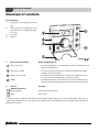
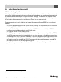
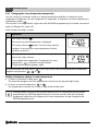
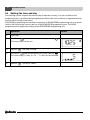
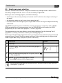
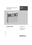
Programming unit
Logamatic EMS
For users
RC25 programming unit
Read carefully before
use.
6 720 642 735 (05/2010) GB
Operating instructions
Overview of controls
Overview of controls
Key to diagram:
1
Flap; pull the recessed grip on the left to
open
2
Rotary selector for changing values and
temperatures or for navigating through
the menus
3
Pin button
4
Display
5
Keys for basic functions:
When the LED lights up,
“AUT” (automatic)
•
the switching program is active (automatic switchover between day and
night room temperatures).
“Day mode” (manual)
•
the heating system operates at the set day room temperature. DHW
heating is on (factory setting).
“Night mode” (manual)
•
the heating system operates at the set night room temperature. Frost
protection is active. DHW heating is off (factory setting).
“DHW”
•
the DHW temperature has fallen below its set value. Pushing this key
means DHW will be heated up again (the LED flashes during heat-up).
6
Keys for
Function:
additional functions:
“Prog” (program)
Selecting a heating program
“Time”
Set the time
In automatic mode, an additional LED lights up with the “AUT” LED to indicate the current operating status (“day mode” or
“night mode”). Exception: in the case of boilers with UBA, only the “AUT” LED illuminates. The “DHW” LED on boilers with
UBA will not illuminate.
2
Logamatic EMS RC25 programming unit - Subject to technical modifications
Contents
Contents
1
Symbols and safety precautions . . . . . . . . . . . . . . . . . . . . . . . . . . . . . . . . . . . . . . . . . . . . . 5
1.1 Key to symbols . . . . . . . . . . . . . . . . . . . . . . . . . . . . . . . . . . . . . . . . . . . . . . . . . . . . . . . . . . . . 5
1.2 Safety instructions . . . . . . . . . . . . . . . . . . . . . . . . . . . . . . . . . . . . . . . . . . . . . . . . . . . . . . . . . 6
2
Product information . . . . . . . . . . . . . . . . . . . . . . . . . . . . . . . . . . . . . . . . . . . . . . . . . . . . . . .
2.1 Product description . . . . . . . . . . . . . . . . . . . . . . . . . . . . . . . . . . . . . . . . . . . . . . . . . . . . . . . .
2.2 Correct use . . . . . . . . . . . . . . . . . . . . . . . . . . . . . . . . . . . . . . . . . . . . . . . . . . . . . . . . . . . . . .
2.3 EU Declaration of Conformity . . . . . . . . . . . . . . . . . . . . . . . . . . . . . . . . . . . . . . . . . . . . . . . .
2.4 Cleaning . . . . . . . . . . . . . . . . . . . . . . . . . . . . . . . . . . . . . . . . . . . . . . . . . . . . . . . . . . . . . . . . .
2.5 Disposal . . . . . . . . . . . . . . . . . . . . . . . . . . . . . . . . . . . . . . . . . . . . . . . . . . . . . . . . . . . . . . . . .
3
Getting started . . . . . . . . . . . . . . . . . . . . . . . . . . . . . . . . . . . . . . . . . . . . . . . . . . . . . . . . . . . . 8
4
Principles of operation . . . . . . . . . . . . . . . . . . . . . . . . . . . . . . . . . . . . . . . . . . . . . . . . . . . .
4.1 Display . . . . . . . . . . . . . . . . . . . . . . . . . . . . . . . . . . . . . . . . . . . . . . . . . . . . . . . . . . . . . . . . .
4.2 Changing the room temperature directly . . . . . . . . . . . . . . . . . . . . . . . . . . . . . . . . . . . . . .
4.3 Notes on range of functions . . . . . . . . . . . . . . . . . . . . . . . . . . . . . . . . . . . . . . . . . . . . . . . .
4.4 Selecting a heating circuit . . . . . . . . . . . . . . . . . . . . . . . . . . . . . . . . . . . . . . . . . . . . . . . . .
4.5 Shutting down/switching off . . . . . . . . . . . . . . . . . . . . . . . . . . . . . . . . . . . . . . . . . . . . . . . .
11
11
12
12
13
14
5
Function control . . . . . . . . . . . . . . . . . . . . . . . . . . . . . . . . . . . . . . . . . . . . . . . . . . . . . . . . . .
5.1 Selecting the operating mode . . . . . . . . . . . . . . . . . . . . . . . . . . . . . . . . . . . . . . . . . . . . . .
5.2 Setting the room temperature . . . . . . . . . . . . . . . . . . . . . . . . . . . . . . . . . . . . . . . . . . . . . .
5.2.1 Changing the room temperature temporarily . . . . . . . . . . . . . . . . . . . . . . . . . . . . . . . . . .
5.2.2 Setting the room temperature for the current operating mode . . . . . . . . . . . . . . . . . . . .
5.2.3 Setting the room temperature for an operating mode which is not the current mode .
5.3 Setting DHW functions . . . . . . . . . . . . . . . . . . . . . . . . . . . . . . . . . . . . . . . . . . . . . . . . . . . .
5.3.1 Checking or changing the DHW temperature . . . . . . . . . . . . . . . . . . . . . . . . . . . . . . . . .
5.3.2 Heating DHW only once . . . . . . . . . . . . . . . . . . . . . . . . . . . . . . . . . . . . . . . . . . . . . . . . . .
5.4 Setting the time and day . . . . . . . . . . . . . . . . . . . . . . . . . . . . . . . . . . . . . . . . . . . . . . . . . . .
5.5 Heating program selection . . . . . . . . . . . . . . . . . . . . . . . . . . . . . . . . . . . . . . . . . . . . . . . . .
15
15
17
18
19
19
20
20
21
22
23
6
Information on setting the programming unit . . . . . . . . . . . . . . . . . . . . . . . . . . . . . . . . 25
6.1 Types of control . . . . . . . . . . . . . . . . . . . . . . . . . . . . . . . . . . . . . . . . . . . . . . . . . . . . . . . . . 25
6.2 Tips for energy efficiency . . . . . . . . . . . . . . . . . . . . . . . . . . . . . . . . . . . . . . . . . . . . . . . . . . 26
Logamatic EMS RC25 programming unit - Subject to technical modifications
7
7
7
7
7
7
3
Contents
7
Environment / disposal . . . . . . . . . . . . . . . . . . . . . . . . . . . . . . . . . . . . . . . . . . . . . . . . . . . . 27
8
Troubleshooting . . . . . . . . . . . . . . . . . . . . . . . . . . . . . . . . . . . . . . . . . . . . . . . . . . . . . . . . . .
8.1 Frequently asked questions . . . . . . . . . . . . . . . . . . . . . . . . . . . . . . . . . . . . . . . . . . . . . . . .
8.2 Fault and service displays . . . . . . . . . . . . . . . . . . . . . . . . . . . . . . . . . . . . . . . . . . . . . . . . .
8.3 Clearing faults (reset) . . . . . . . . . . . . . . . . . . . . . . . . . . . . . . . . . . . . . . . . . . . . . . . . . . . . .
28
28
30
33
Index . . . . . . . . . . . . . . . . . . . . . . . . . . . . . . . . . . . . . . . . . . . . . . . . . . . . . . . . . . . . . . . . . . . . 34
4
Logamatic EMS RC25 programming unit - Subject to technical modifications
Symbols and safety precautions
1
1
Symbols and safety precautions
1.1 Key to symbols
Warnings
Warnings in this document are framed and identified by a warning triangle printed
against a grey background.
If there is a danger due to electricity, the exclamation mark in the warning triangle is
replaced by a lightning symbol.
Keywords at the start of a warning indicate the type and seriousness of the ensuing risk if measures
to prevent the risk are not taken.
• NOTE indicates that material losses may occur.
• CAUTION indicates that minor to medium injury may occur.
• WARNING indicates that severe injury may occur.
• DANGER indicates a risk to life.
Important information
Important information where there is no risk to people or property is indicated with the
adjacent symbol. It is bordered by lines above and below the text.
Additional symbols
Symbol
Explanation
B
Action step
Æ
Cross-reference to other parts of this document or to other documents
•
List/list entry
–
List/list entry (level 2)
Tab. 1
Logamatic EMS RC25 programming unit - Subject to technical modifications
5
1
Symbols and safety precautions
1.2 Safety instructions
Installation and commissioning
B Observe these instructions to ensure satisfactory operation.
B The appliance must only be installed and commissioned by an approved contractor.
Risk to life from electric shock
B Ensure that electrical connections are only made by authorised electrical contractors.
B Observe the connection diagram.
B Before installation, isolate all poles of the power supply. Secure against unintentional
reconnection.
B Never install this appliance in wet rooms.
B Never connect this appliance to the 230 V mains.
Damage due to operator error
Operator errors can lead to injuries and/or material losses.
B Ensure that children never operate this appliance unsupervised or play with it.
B Ensure that only individuals who can operate this appliance correctly have access to it.
Warning: frost
The heating system can freeze up in cold weather if it is not in operation:
B Leave the heating system permanently switched on.
B Enable frost protection.
B In case of faults: remedy any faults immediately.
6
Logamatic EMS RC25 programming unit - Subject to technical modifications
Product information
2
2
Product information
2.1 Product description
The programming unit makes it easy to operate your Buderus heating system with Energy
Management System (EMS). For example, simply pressing one key starts DHW heating at any time;
alternatively, using the rotary selector can change the room temperature in the entire home. The
thermostatic radiator valves only need to be adjusted if an individual room is too cold or too hot.
The automatic control with the adjustable switching program ensure energy efficient operation by
reducing the room temperature at certain times or by shutting down the entire heating system
(adjustable night setback).
The heating system is controlled in such a way that you benefit from optimum heating comfort and
minimum energy consumption.
2.2 Correct use
The programming unit must only be used to operate and control Buderus heating systems in
domestic and commercial buildings.
The boiler must be equipped with EMS (energy management system) or UBA (universal burner
controller). We recommend always operating the heating system with a programming unit
(otherwise the system only operates in emergency mode).
2.3 EU Declaration of Conformity
The design and operation of this product conforms to European Directives and the supplementary
national requirements. Its conformity is demonstrated by the CE designation. You can call up the
Declaration of Conformity for this product on the internet at www.buderus.de/konfo or request a
copy from your local Buderus sales office.
2.4 Cleaning
B Clean the programming unit only with a damp cloth.
2.5 Disposal
B Dispose of packaging in an environmentally responsible manner.
B When replacing components, dispose of the used ones in an environmentally responsible
manner.
Logamatic EMS RC25 programming unit - Subject to technical modifications
7
3
3
Getting started
Getting started
Setting room temperatures (Æ Chapter 5.2, page 17)
Initial situation: the flap is closed.
What do I do ...
Operation
Input range
if it is temporarily
too cold/hot in the
entire home on a
particular day?
B Turn the rotary selector
to set
the required room temperature.
B Release the rotary selector.
The modified room temperature is
saved (“temporary set room
temperature”
) is saved.
The standard display reappears.
B Press one of the keys
,
or
to cancel the temporary set
room temperature and to enable the
selected operating mode.
Factory
setting
In automatic mode, the modified room
temperature remains active until the
next changeover between night/day
mode.
if it is
permanently too
cold/hot in the
entire home?
Æ Changing the
room temperature
in automatic mode
Tab. 2
8
B To change the day/night time room
temperature in automatic mode:
hold down key
and
simultaneously turn rotary
selector
.
The value can be changed
As for day/night
21 °C/
17 °C
Getting started - setting temperatures
Logamatic EMS RC25 programming unit - Subject to technical modifications
Getting started
3
What do I do ...
Operation
Input range
Factory
setting
for one-off heating
outside the usual
times (outside the
switching
program)?
B Activate manual day mode: hold
down key
and simultaneously
turn rotary selector
.
The value can now be changed.
The LED adjacent to key
illuminates.
6 °C – 30 °C
21 °C
5 °C – 29 °C
17 °C
30 °C –
60(80) °C
60 °C
Æ Manual day
mode (“continuous
heating”);
automatic mode is
switched off
to save energy
during long
absences?
Æ Manual night
mode
(“permanently
reduced”);
automatic mode is
switched off
if the DHW
temperature is too
cold/hot?
Tab. 2
To end the one-off heating phase:
B Activate automatic mode again:
press
.
The LED next to key
illuminates.
B Activate manual night mode: hold
down key
and simultaneously
turn rotary selector
.
The value can be changed.
The LED next to
lights up.1)
When you return:
B Activate automatic mode again:
press
.
The LED next to key
illuminates.
B Hold down
and simultaneously
turn rotary selector
.
The value can be changed.
Getting started - setting temperatures
Logamatic EMS RC25 programming unit - Subject to technical modifications
9
3
Getting started
Getting started – additional functions
What do I do ...
Operation
Further information
to set the time?
B Open flap.
B Hold down
and simultaneously
turn rotary selector
.
The time can be set.
Æ page 22
to select the heating
program?
B Open flap.
B Hold down
and simultaneously
turn rotary selector
.
The heating program can be selected.
Æ page 23
Tab. 3
10
Getting started – additional functions
Logamatic EMS RC25 programming unit - Subject to technical modifications
Principles of operation
4
4
Principles of operation
4.1 Display
The display shows set and actual values and temperatures, e.g. the actual room temperature
(factory-set to be the permanent display).
Fig. 1
1
2
3
4
5
6
7
8
Display elements explained
Day (1 = Mo, 2 = Tu, ...7 = Su)
Set or actual value/temperature
“Temperature” display in °C
“Outside temperature” display
“Actual room temperature” display
Display:
a) Room temperature can now be adjusted or
b) Room temperature has temporarily changed
“Summer mode” display
Operating status symbols
The display shows four horizontal bars if you try to change a value which
cannot be modified of if an adjustment is not possible.
Logamatic EMS RC25 programming unit - Subject to technical modifications
11
4
Principles of operation
4.2 Changing the room temperature directly
If your entire home is too cold or too hot, raise or reduce the room temperature using the rotary
selector, and leave the thermostatic radiator valves unchanged.
B Turn the rotary selector
to set the required room temperature.
B Release the rotary selector.
The modified room temperature is saved (“temporary set room temperature”
The standard display reappears.
) is saved.
The temporary temperature setting is retained until you press one of the keys
,
or
or until the heating system changes its operating mode (for example, into night
mode).
For further ways to change the room temperature, see Chapter 5.2, page 17.
4.3 Notes on range of functions
These instructions describe all possible functions of the programming unit. Some of these functions
may not be available, depending on which boiler and version of the burner control unit are used. For
more information, refer to the relevant chapter. Consult your heating contractor if you have further
questions.
12
Logamatic EMS RC25 programming unit - Subject to technical modifications
Principles of operation
4
4.4 Selecting a heating circuit
What is a heating circuit?
A heating circuit describes the circuit taken by the heating water from the boiler to the radiators and
back again. Multiple heating circuits can be connected to one boiler; for example, one heating circuit
for radiators and another heating circuit for underfloor heating. The radiators are supplied with a
higher flow temperature than the underfloor heating system. The flow temperature is the temperature
of the heating water generated by the boiler as it flows into the heating circuit.
The programming unit can be tied into the Energy Management System (EMS) by two different
methods:
• As the only programming unit in the system (factory setting): the programming unit is installed in
the living space or on the boiler.
Example: detached house with one heating circuit. If DHW is to be controlled, an RC35
programming unit will be needed to comply with part L.
• As a remote control for one heating circuit: 1)
The RC25 programming unit is operated in unison with a higher programming unit (e.g. RC35).
The RC35 programming unit is installed either in the living space or on the boiler, and regulates
one heating circuit (e.g. for the main apartment). The RC25 programming unit captures the room
temperature in a separate living area and regulates this second heating circuit. Basic settings for
the heating system are made at the RC35. Consequently, these settings become available for
the heating circuit with the RC25 programming unit.
Examples: underfloor heating on one floor, radiators on another; or a flat together with a separate
living area or clinic.
1) Not available on boilers with UBA.
Logamatic EMS RC25 programming unit - Subject to technical modifications
13
4
Principles of operation
HC1
HC1
HC1
Fig. 2
1
2
HC2
Options for a heating system with one or two heating circuits
One programming unit controls one heating circuit. (Must be used in conjunction with RC35 to comply
with part L).
Each heating circuit has its own programming unit / remote control unit.
4.5 Shutting down/switching off
The RC35 programming unit is powered via the heating system and remains permanently on.
The heating system is only switched off for maintenance work, for example.
B To start up and shut down the heating system: set the ON/OFF switch on the boiler programming
unit to 1 (ON) or 0 (OFF).
After shutting down or in the event of a power failure, the time and day are retained for
several hours. All other settings are retained permanently.
14
Logamatic EMS RC25 programming unit - Subject to technical modifications
Function control
5
5
Function control
This chapter describes how you can change the room and DHW temperatures. You control these
functions by pressing a key on the r.h. side or behind the programming unit flap, or by turning the
rotary selector.
5.1 Selecting the operating mode
You may operate the programming unit in two different ways:
• In automatic mode
• In manual mode
You can activate the operating mode directly by pressing the specified key.
Operating mode
Automatic
(recommended setting)
Key
Explanation
The switching program is active. The system will
change over automatically between day mode and night
mode at the set time (switching point).1) At night the
heating system will operate at a reduced room
temperature (factory setting; night shutdown is also
possible).
DHW heating is on during the day and off at night
(factory setting).
The LED for the automatic key illuminates, along with
the LED for either day or night mode, depending on
which is currently active.
Tab. 4
Explanation of the operating modes
Logamatic EMS RC25 programming unit - Subject to technical modifications
15
5
Function control
Operating mode
Manual daytime operation
Continuous heating
Key
Explanation
Factory setting: 21 °C.
Manual day mode is useful if you want to heat outside
the usual times. Automatic mode is switched off.
DHW heating is on (factory setting).
Only the day mode LED illuminates.
Manual nighttime operation
Permanently reduced
Factory setting: 17 °C.
The heating system operates with a reduced room
temperature (factory setting). Manual night mode is
useful if you are occasionally absent for long periods.
Automatic mode is switched off.
DHW heating is off (factory setting).
Only the night mode LED illuminates.
Tab. 4
Explanation of the operating modes
1) The automatic day and night modes correspond to the manual day and night modes. The only difference lies
in the automatic changeover.
If the heating system operates under weather-compensated control (Æ Chapter 6.1,
page 25): during spring and autumn, you may feel that your home is too cold, even
though your heating system is in summer mode on account of the outside temperature
(only DHW heating). In that case, select manual mode to heat on an hourly basis.
16
Logamatic EMS RC25 programming unit - Subject to technical modifications
Function control
5
5.2 Setting the room temperature
NOTICE: System damage due to frost!
If room temperatures are set below 10 °C, rooms may cool down so much that pipes in
external walls (for example) may freeze in cold weather.
B Set room temperatures higher than 10 °C.
Generally, you can adjust the room temperature using the rotary selector. This can be done in three
different ways:
• Changing the room temperature temporarily. The modified settings are retained until the heating
system changes into a different operating mode (e.g. night mode).
• Changing the room temperature for the current operating mode (e.g. automatic day mode). The
modified setting applies to automatic day mode from then onwards.
• Changing the room temperature for an operating mode that is not currently selected (e.g.
changing the night room temperature during the day). The modified setting applies to this
operating mode from then onwards.
The actual room temperature is shown as the permanent display. Your heating
contractor can also set a different permanent display.
Logamatic EMS RC25 programming unit - Subject to technical modifications
17
5
Function control
5.2.1 Changing the room temperature temporarily
You are currently in automatic mode or in manual mode and would like to change the room
temperature (“temporary set room temperature”) temporarily. A temporary set room temperature is
indicated by symbol
.
This function is not supported in conjunction with the RC30 programming unit. Instead, use manual
mode (Æ Chapter 5.1, page 15).
Initial situation: the flap is closed.
Operation
1.
Turn rotary selector
Result
.
The current set room temperature is displayed.
Turn rotary selector
further. Turn the rotary selector
clockwise to increase the room temperature and anticlockwise to lower it.
2.
When you have reached the required room temperature,
release the rotary selector.
The modified room temperature (“temporary set room
temperature”
) is saved (no longer flashes).
The permanent display appears again.
In manual mode, the LED next to
applies until you press
,
or
is not lit up. In this case, the modified room temperature
.
Ending a temporary change in room temperature
B To return to automatic mode, press
.
The automatic program uses the temperatures normally set for day and night mode.
B To return to manual mode, press
or
.
The temperatures normally set for day or night mode will be used.
If holiday mode is active for the relevant heating circuit in conjunction with the RC35
programming unit (RC25 programming unit as remote control), then the set holiday
temperature rather than the temporary set room temperature can be changed at the
RC25 programming unit.
18
Logamatic EMS RC25 programming unit - Subject to technical modifications
Function control
5
5.2.2 Setting the room temperature for the current operating mode
The set room temperature applies to the currently enabled heating mode, i.e. day or night mode. You
can recognise the currently enabled heating mode because the LED of the respective symbol
illuminates. You are currently in automatic mode and would like to change the room temperature.
Operation
1.
Hold down
Result
and simultaneously turn rotary selector
.
Turn rotary selector
further. Turn the rotary selector
clockwise to increase the room temperature and anticlockwise to lower it.
2.
When you have reached the required room temperature,
release the rotary selector.
Automatic mode is now active with the modified room
temperatures. The LED next to key
illuminates.
The permanent display will then appear again.
5.2.3 Setting the room temperature for an operating mode which is not the current mode
You may also adjust the room temperature for an operating mode that is not currently enabled.
For example, you are currently in automatic “Day” mode and would like to alter the set night
temperature.
Operation
1.
Hold down
Result
and simultaneously turn rotary selector
.
Turn rotary selector
further. Turn the rotary selector
clockwise to increase the room temperature and anticlockwise to lower it.
2.
When you have reached the required room temperature,
release the rotary selector.
Automatic mode is now active with the modified room
temperatures. The LED next to key
illuminates.
The permanent display will then appear again.
Logamatic EMS RC25 programming unit - Subject to technical modifications
19
5
Function control
5.3 Setting DHW functions
Risk of scalding from DHW temperatures over 60 °C!
WARNING: Risk of scalding!
The factory setting for the DHW temperature is 60 °C. There is a risk of scalding at the
hot water draw-off points if the temperature is set higher than this and also following
thermal disinfection.
B If the temperature set is higher than 60 °C or following thermal disinfection, never
open any hot water tap without mixing in cold water as well.
The programming unit also offers you the option of heating DHW in an energy-conscious manner.
The setting is subject to how the programming unit was installed (Æ Chapter 6.1, page 25):
• If the RC25 programming unit operates as the only programming unit in the system, DHW
heating commences automatically 30 minutes prior to the start of day mode of the heating
program. DHW is not produced during night mode. In day mode, the DHW circulation pump is
started twice per hour for three minutes to safeguard the constant supply of taps with hot water.1)
The DHW temperature can be set to a maximum of 60 °C (= factory setting). For UK an RC35
must be used for DHW control to comply with part L.
• If the RC25 programming unit is installed as a remote control for one heating circuit,2) then DHW
heating and the operation of the DHW circulation pump will be set for the entire heating system
with the higher programming unit (e.g. RC30/RC35). The set DHW temperature can be changed
with the RC30/RC35 or the RC25 programming units; however, the setting range of the RC30/
RC35 programming units applies (maximum 80 °C).
5.3.1 Checking or changing the DHW temperature
Initial situation: the flap is closed.
Operation
Result
1.
Hold down
and simultaneously turn rotary selector
The value can be changed.
2.
When you have reached the required DHW temperature,
release the rotary selector.
The modified temperature is saved.
The standard display appears again.
.
1) Function dependent on the boiler used.
2) Function not available on boilers with UBA.
20
Logamatic EMS RC25 programming unit - Subject to technical modifications
Function control
5
5.3.2 Heating DHW only once1)
To save energy, during day mode DHW is only reheated automatically when its temperature falls
5 °C below the set DHW temperature.
If you need large amounts of hot water one evening or outside the set times for day mode, you can
heat up the DHW.
Initial situation: the flap is closed.
Operation
1.
The LED of key
illuminates if the DHW temperature falls below the set value. To heat
up the DHW manually:
press
.
The LED at key
flashes. Heat-up starts, and is later terminated automatically.
2.
If you want to stop the heating process, press
again.
Subject to the size of the DHW cylinder and the boiler output, DHW will be available
after approx. 10 – 30 minutes. With instantaneous water heaters or combi boilers,
DHW is available almost immediately.
1) Function not available on boilers with UBA.
Logamatic EMS RC25 programming unit - Subject to technical modifications
21
5
Function control
5.4 Setting the time and day
Your heating system requires the time and day to operate correctly. You can set both at the
programming unit, e.g. following a prolonged power failure (the clock continues to operate even after
a power failure lasting a few hours).
If the RC25 programming unit has been assigned to an RC30/RC35 programming unit as a remote
control, the time and day can only be set at the RC30/RC35 programming unit. The RC25
programming unit adopts the settings of the RC30/RC35 programming unit.
Operation
Result
1.
Open flap.
2.
Hold down
and simultaneously turn rotary selector
The current time can be set.
3.
Release
4.
Hold down
and simultaneously turn rotary selector
.
The current day (1 = Mo, 2 = Tu, ... 7 = Su) can be selected.
5.
Release
22
.
. The time is saved.
. The day is saved.
Logamatic EMS RC25 programming unit - Subject to technical modifications
Function control
5
5.5 Heating program selection
Automatic mode ensures automatic changeover between day and night mode at defined times.
The factory settings means 21 °C or 17 °C are set for day or night mode.
Before you select a heating program, consider the following:
• At what time in the morning should your home be warm? Is this time also subject to the day of
the week?
• Are there days when you don't want to heat during the day?
• From what time in the evening do you no longer need to heat? This may also depend on the day
of the week.
If the RC25 programming unit is installed as a remote control unit in conjunction with an RC30/
RC35 programming unit, heating programs from the RC30/RC35 can be used by the RC25
programming unit (so-called “Own programs”, Æ Tab. 5, page 24).
The programming unit has eight different, preset heating programs. See the following Tab. 5,
page 24 for a summary of the times of these preset heating programs.
Please check which heating program best meets your requirements to optimise heating comfort and
energy efficiency. Primarily check the number and times of the switching points for day and night
mode. Program Pr1 (“family” program) is preset at the factory.
Operation
Result
1.
Open flap.
2.
Hold down
displayed.
3.
Select the required heating program using rotary selector
(Æ Tab. 5, page 24).
4.
Release
. The selected program is saved.
The permanent display will then appear again.
. The currently selected heating program is
The selected heating program will only be effective if automatic mode has been selected
(Æ Chapter 5.1, page 15).
Logamatic EMS RC25 programming unit - Subject to technical modifications
23
Function control
5
Start and stop points in the heating programs
No.
Program
Day
ON
OFF
Pr1
Family
Mo–Th
5:30
22:00
(factory setting)
Pr2
Early morning
(early shift work)
Fr
5:30
23:00
Sa
6:30
23:30
Su
7:00
22:00
Mo–Th
4:30
22:00
ON
OFF
Fr
4:30
23:00
Sa
6:30
23:30
Su
7:00
22:00
Evening
Mo– Fr
6:30
23:00
(late shift work)
Sa
6:30
23:30
Su
7:00
23:00
Morning
Mo–Th
5:30
8:30
12:00
22:00
(part-time work in
Fr
5:30
8:30
12:00
23:00
the morning)
Sa
6:30
23:30
Su
7:00
22:00
Afternoon
Mo–Th
6:00
11:30
16:00
22:00
(part-time work in
Fr
6:00
11:30
15:00
23:00
the afternoon)
Sa
6:30
23:30
Su
7:00
22:00
Midday
Mo–Th
6:00
8:00
11:30
13:00
(at home at midday)
Fr
6:00
8:00
11:30
23:00
Pr3
Pr4
Pr5
Pr6
Pr7
Single
Pr8
Elderly
Pr9
New program
Sa
6:00
23:00
Su
7:00
22:00
Mo–Th
6:00
8:00
16:00
22:00
Fr
6:00
8:00
15:00
23:00
Sa
7:00
23:30
Su
8:00
22:00
Mo–Su
5:30
22:00
ON
OFF
17:00
22:00
Constant heating mode (24 h). This is displayed on the RC25 programming unit whilst a new
heating program is entered in the RC30/RC35 programming unit (only if the RC25 is used as a
remote control).1)
Pr0
Own program
Only if the RC25 programming unit is set up as a remote control:
(from RC30/RC35) Enables “Own program 1” set up in the RC30/RC35 programming unit for the heating circuit of
the RC25 programming unit.1)
Pr10
Own program
(from RC35)
Only if the RC25 programming unit is set up as a remote control in conjunction with the RC35:
Enables “Own program 2” set up in the RC35 programming unit for the heating circuit of the
RC25 programming unit.1)
Tab. 5
Heating programs (ON = day mode, OFF = night mode)
1) Function not available on boilers with UBA.
24
Logamatic EMS RC25 programming unit - Subject to technical modifications
Information on setting the programming unit
6
6
Information on setting the programming unit
6.1 Types of control
The heating system can be operated in three control modes. Depending on your requirements, your
heating contractor will select and set up one of these options:
Room temperature control
With this control mode, the programming unit must be fitted in a room that is fairly typical for the
home. The programming unit records the room temperature in this “reference room”. Control of the
flow temperature is determined by the set room temperature and the actual room temperature.
Consequently external temperature influences in the reference room (e.g. open windows, sunlight
or heat from a fireplace) will affect your entire home.
Set the room temperature of your home or reference room at the programming unit. You can
produce higher or lower temperatures in the other rooms by adjusting the thermostatic radiator
valves.
Weather-compensated control
The temperature of the heating water in the boiler is defined by the heating curve. You can select
whether this heating curve will be influenced solely by the outside temperature, or whether the
temperature in the reference room should also have an influence.
• Purely weather-compensated control:
The outside temperature is captured by a temperature sensor. The flow temperature is calculated
solely on the basis of the outside temperature in accordance with the set heating curve.
You can set the room temperature for the entire home at the programming unit (which will shift
the heating curve up or down). You must adjust the thermostatic radiator valves in every room in
order to achieve the required room temperature.
• Weather-compensated control with room temperature hook-up:
With this control mode the flow temperature is primarily determined by the outside temperature,
but is also influenced by the room temperature to the extent selected by your heating contractor.
The following applies to room temperature control and for weather-compensated
control with room temperature hook-up:
The thermostatic radiator valves in the “Reference room” (the room where the
programming unit is installed) must be fully open! Control of the flow temperature is
determined by the room temperature recorded there. It must not be limited by closed
thermostatic valves.
Logamatic EMS RC25 programming unit - Subject to technical modifications
25
6
Information on setting the programming unit
6.2 Tips for energy efficiency
• You can save around 6 % on your heating costs by reducing the daytime
room temperature by 1 °C.
• Only heat if you need warmth. Use the switching programs for automatic
night setback.
• Air your home wisely: leave the windows wide open for a few minutes
rather than leaving them slightly open all the time.
• Close the thermostatic radiator valves while airing rooms.
• Make sure that your windows and doors form a proper seal.
• Never position large objects such as a sofa immediately in front of radiators (maintain a clearance
of at least 50 cm). Otherwise, the heated air cannot circulate and heat the room adequately.
• You can also increase the energy efficiency of your DHW heating: compare the times when you
want your rooms to be warm with the times when you need hot water. It may be practical to use
a separate switching program for DHW heating.
• Arrange for your heating contractor to service your heating system annually.
26
Logamatic EMS RC25 programming unit - Subject to technical modifications
Environment / disposal
7
7
Environment / disposal
Environmental protection is a fundamental corporate strategy of the Bosch Group.
The quality of our products, their economy and environmental safety are all of equal importance to
us and all environmental protection legislation and regulations are strictly observed.
We use the best possible technology and materials for protecting the environment taking account
of economic considerations.
Packaging
Where packaging is concerned, we participate in country-specific recycling processes that ensure
optimum recycling.
All packaging materials are environmentally compatible and can be recycled.
Used appliances
Used appliances contain materials that should be recycled.
The components are easy to separate and the plastics carry identification markings. This allows the
various assemblies to be appropriately sorted for recycling or disposal.
Logamatic EMS RC25 programming unit - Subject to technical modifications
27
8
8
Troubleshooting
Troubleshooting
This chapter deals with frequently asked questions about your heating system. This will in many
cases enable you to eliminate suspected faults. At the end of the chapter you will find a table listing
faults and corresponding remedies.
8.1 Frequently asked questions
Why do I set a room temperature, even though it is not recorded?
When you set the room temperature – even if it is not recorded, as with weather-compensated
control – you are changing the heating curve. This changes the room temperature, because the
temperature of the heating water changes and with it the temperature of the radiators.
Why does the room temperature measured with a separate thermometer not correlate
with the set room temperature?
The room temperature is influenced by a number of different variables. If the RC25 programming
unit is installed on a cold wall, it will be influenced by the cold temperature of the wall. It will be
influenced by the heat from a fireplace or chimney, for example, if it is installed in a warm part of the
room. Therefore, a separate thermometer can indicate a different room temperature than that set at
the RC25 programming unit. To compare the actual room temperature with the values measured by
another thermometer, the following is important:
• The separate thermometer and the room controller must be physically close to each other.
• The separate thermometer must be accurate.
• When comparing, do not measure the room temperature when the heating system is heating up,
as the two devices may react at different speeds to the change in temperature.
If you have followed these instructions and you can still detect a discrepancy, you can calibrate the
room temperature display (Æ page 17).
Why do the radiators get too hot when the outside temperature is relatively high?
If you have a heating system with one heating circuit and no mixing valve (heating circuit 1), this is
normal. The pump only starts up when the boiler reaches a predefined flow temperature. If the flow
temperature is higher than required based on the outside temperature, the radiators may get hotter
for a short time. The heating control unit detects this and responds accordingly after a short time.
Do not adjust the thermostatic valves on the radiators and wait until the set room temperature is
reached. Even in summer mode, radiators may be heated briefly under specific circumstances:
namely when the pump is started up automatically at a predefined interval to prevent it from “seizing
up” (jamming). If the pump happens to start immediately after DHW heating, the unusable residual
heat is dissipated via the heating circuit and the radiators.
28
Logamatic EMS RC25 programming unit - Subject to technical modifications
Troubleshooting
8
Why does the pump run at night, even though the home is not being heated at all or only
very little?
This depends on the setting chosen by your heating contractor for night setback.
• Reduced operation: The pump still runs even if the home is only being heated a little to achieve
a low room temperature.
• Shutdown mode: The heating system (and therefore also the pump) is automatically shut down
in night mode. If the outside temperature falls below the frost protection temperature, the pump
is automatically switched on by the “Frost protection” function.
• Shutdown mode and Room setback mode: The heating system is switched on automatically
when the captured temperature falls below the set value. The pump will then also start.
The actual room temperature is higher than the set room temperature. Why is the boiler
still running?
The boiler may be running to heat up DHW. Your heating system can be set to three possible control
modes (Æ page 25):
• Room temperature control: The boiler shuts down when the set room temperature has been
reached.
• Weather-compensated control: The heating system runs on the basis of the outside temperature.
• Weather-compensated control with room temperature hook-up: The heating system takes
advantage of both the above control modes.
The boiler can still operate in the latter two cases, even if the captured room temperature is higher
than the set room temperature.
Logamatic EMS RC25 programming unit - Subject to technical modifications
29
8
Troubleshooting
8.2 Fault and service displays
The programming unit makes a distinction between three types of messages:
• Service message
• Fault message (= system fault; incorrect settings on the programming unit, or component faulty)
• Service messages (indicating that some maintenance work is required)
NOTICE: System damage due to frost!
The heating system can freeze up if it has been switched off through a fault shutdown.
B Try and clear the fault.
B If that is not possible, notify your heating contractor immediately.
The faults depend on the boiler used. Information about the faults can be found in the
boiler documentation.
“Code” column in Tab. 6
The messages are identified by codes. These inform your heating contractor about the possible
cause.
The codes are issued in two parts. The first indicates the service code (display code) (e.g. A01).
Turning the rotary selector clockwise displays the fault code (e.g. 816).
By means of the service code, the display indicates, whether a Fault Condition (= system fault) or
service message is currently active.
1. In case of a fault message, turn rotary selector
clockwise.
The fault code will be displayed.
2. Check whether you can eliminate the fault yourself with a reset (Æ Chapter 8.3) or by means of
the explanations in Tab. 6.
3. Otherwise notify your heating contractor immediately (stating the code).
4. In case of a service message, check whether the message can be cleared with the aid of the
explanations in Tab. 6.
5. Otherwise notify your heating contractor immediately (stating the code).
30
Logamatic EMS RC25 programming unit - Subject to technical modifications
Troubleshooting
8
The following table explains the possible fault and service displays:
Code
Display
Nothing appears on the
display
After start-up:
Cause
Heating system has
been switched off.
Remedy
B Switch on the heating
system.
The power supply to the B Check that the
heating system has
programming unit is
been interrupted.
correctly seated in its wall
mounting base.
B Check that the cables on
the programming unit wall
mounting base are
connected.
After start-up, data is
B Wait a few seconds.
transferred between
EMS/UBA and the
RC35 (no fault).
In addition, the LEDs flash
alternately.
When changing a setting: This parameter cannot
be modified or this
setting is not
permissible.
Tab. 6
Fault and service displays
Logamatic EMS RC25 programming unit - Subject to technical modifications
31
8
Troubleshooting
Code
Display
xxx xxx Example:
A01
Cause
The heating system or
the programming unit
has developed a fault.
The cause of the fault
may be temporary. The
heating system
The LEDs flash alternately. automatically returns to
The display does not flash. standard mode.
In addition the display
The heating system or
flashes.
the programming unit
has developed a fault.
If a fault is shown as a
flashing code, clear it
with a reset.
816
Communication to EMS
is faulty, possibly due to
a loose contact or
electromagnetic
interference, for
example.
A11
802
A11
803
A18
802
Tab. 6
32
Remedy
If the permanent display does
not automatically return:
B Notify your heating
contractor.
B Clear the fault
(Æ Chapter 8.3).
B Check that the
programming unit is
correctly seated in its wall
mounting base.
B Check that the cables on
the programming unit wall
mounting base are
connected.
Time or date settings are B Enter the time or date so
missing. This may have
that the switching program
been caused by a
and other functions can
lengthy power failure, for
work correctly.
example.
Time or date settings are B Enter the time or date so
missing. This may have
that the switching program
been caused by a
and other functions can
lengthy power failure, for
work correctly.
example.
Fault and service displays
Logamatic EMS RC25 programming unit - Subject to technical modifications
Troubleshooting
Code
Hxx1)
Display
Example:
H 71)
8
Cause
A service is required.
The heating system
keeps operating as far
as possible.
Remedy
B Make arrangements to have
the system serviced by your
heating contractor.
The water pressure in
the heating system has
dropped to a low level.
This is the only service
message (H 7) that you can
deal with yourself.
This value is only
B Top up the heating water
displayed if your heating
(Æ boiler operating
system is equipped with
instructions).
a digital pressure
sensor. Otherwise
check the operating
pressure from time to
time at the pressure
gauge.
Tab. 6
Fault and service displays
1) Function not possible on boilers with UBA.
8.3 Clearing faults (reset)
Some faults can be rectified by resetting the system. This applies to locking faults, for example.
Locking faults are those which cause the display on the boiler programming unit to flash.
B Press reset on the boiler programming unit to clear the fault.
For instructions regarding the reset function on the boiler programming unit, see the technical
documentation for the boiler and/or boiler programming unit.
B If the fault cannot be cleared (display continues to flash), notify your heating contractor.
Logamatic EMS RC25 programming unit - Subject to technical modifications
33
Index
Index
A
Automatic mode . . . . . . . . . . . . . . . . . . . . . . . 15
C
Cleaning . . . . . . . . . . . . . . . . . . . . . . . . . . . . . . . 7
Continuous heating (manual day) . . . . . . . . .15
D
Day mode . . . . . . . . . . . . . . . . . . . . . . . . . . . . .15
DHW temperature, setting . . . . . . . . . . . . . . .20
DHW, heating up once . . . . . . . . . . . . . . . . . .20
Disposal . . . . . . . . . . . . . . . . . . . . . . . . . . . . . . . 7
E
Energy . . . . . . . . . . . . . . . . . . . . . . . . . . . . . . . . 7
- tips for energy efficiency . . . . . . . . . . . . . .26
Environment / disposal . . . . . . . . . . . . . . . . . .27
F
Faults . . . . . . . . . . . . . . . . . . . . . . . . . . . . . . . .30
Faults, clearing . . . . . . . . . . . . . . . . . . . . . . . .33
Flow temperature . . . . . . . . . . . . . . . . . . . . . .13
Frost . . . . . . . . . . . . . . . . . . . . . . . . . . . . . . 6, 33
- faults when there is a risk of frost . . . . . . .30
Frost protection . . . . . . . . . . . . . . . . . . . . . . . .29
P
Packaging . . . . . . . . . . . . . . . . . . . . . . . . . . . . 27
Permanently reduced (manual night) . . . . . . 15
Power failure . . . . . . . . . . . . . . . . . . . . . . . . . . 14
Pump . . . . . . . . . . . . . . . . . . . . . . . . . . . . . . . . 29
R
RC25 heating circuits . . . . . . . . . . . . . . . . . . 13
Recycling . . . . . . . . . . . . . . . . . . . . . . . . . . . . . 27
Reduced mode . . . . . . . . . . . . . . . . . . . . . . . . 29
Reference room . . . . . . . . . . . . . . . . . . . . . . . 25
Remote control . . . . . . . . . . . . . . . . . . . . . . . . 13
Reset . . . . . . . . . . . . . . . . . . . . . . . . . . . . . . . . 33
Room setback mode . . . . . . . . . . . . . . . . . . . 29
Room temperature
- changing temporarily . . . . . . . . . . . . . . . . . 18
- discrepancy in displayed temperature . . . 28
- too cold/too hot . . . . . . . . . . . . . . . . . . . . . . 8
Room temperature control . . . . . . . . . . . 25, 29
G
Getting started . . . . . . . . . . . . . . . . . . . . . . . . . 8
S
Safety instructions . . . . . . . . . . . . . . . . . . . . . . 6
Shutdown mode . . . . . . . . . . . . . . . . . . . . . . . 29
Shutting down . . . . . . . . . . . . . . . . . . . . . . . . . 14
Start point . . . . . . . . . . . . . . . . . . . . . . . . . . . . 24
Stop point . . . . . . . . . . . . . . . . . . . . . . . . . . . . 24
Switching off . . . . . . . . . . . . . . . . . . . . . . . . . . 14
H
Heating circuit
- Explanation . . . . . . . . . . . . . . . . . . . . . . . . .13
Heating circuit, selecting . . . . . . . . . . . . . . . .13
T
Temperature, see Room temperature
Thermostatic valves . . . . . . . . . . . . . . . . . .7, 25
Types of control . . . . . . . . . . . . . . . . . . . . . . . 25
M
Manual day/night mode . . . . . . . . . . . . . . . . .15
U
Used appliances . . . . . . . . . . . . . . . . . . . . . . . 27
N
Night mode . . . . . . . . . . . . . . . . . . . . . . . . . . .15
Night setback . . . . . . . . . . . . . . . . . . . . . . . . .29
W
Weather-compensated control . . . . . . . 25, 29
O
Operation modes . . . . . . . . . . . . . . . . . . . . . .15
Outside setback mode . . . . . . . . . . . . . . . . . .29
Outside temperature, higher . . . . . . . . . . . . .28
34
Logamatic EMS RC25 programming unit - Subject to technical modifications
Notes
Logamatic EMS RC25 programming unit - Subject to technical modifications
35
Buderus
Cotswold Way, Warndon, Worcester WR4 9SW
Customer service: 0844 892 3004
Technical support: 0844 892 4224
www.buderus-commercial.co.uk
In the UK and IE, Buderus is a brand name
of Bosch Thermotechnology Ltd.