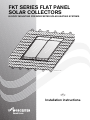
1
FKT SERIES FLAT PANEL
SOLAR COLLECTORS
IN ROOF MOUNTING FOR WORCESTER SOLAR HEATING SYSTEMS
63043975.00-1.SD
GB
Installation instructions
About this manual
This installation manual contains important
information for the safe and appropriate installation of
the roof mounted solar collectors.
Notes are included with important information for
situations in which there is no danger for persons or
equipment.
These technical documents should be retained in a
safe place. These may also be inspected at the
manufacturer's premises.
The activities described in the installation manual
assume expertise based on completed vocational
training in gas or water-related installation. Only carry
out these installation steps, if you possess these
skills.
B Hand these installation instructions to the
customer.
B Explain to the customer the function and operation
of the related devices.
2
6 720 613 057 (2006/04)
1
General information
2
Specifications .
3
Safety
. . . . . . . . . . . . . . . . . . . . . . . . . . . . . . . . . . . . . . . . . .4
. . . . . . . . . . . . . . . . . . . . . . . . . . . . . . . . . . . . . . . . . . . . . .5
. . . . . . . . . . . . . . . . . . . . . . . . . . . . . . . . . . . . . . . . . . . . . . . . . . . . .6
3.1 Correct use . . . . . . . . . . . . . . . . . . . . . . . . . . . . . . . . . . . . . . . . . . . . . . .7
3.2 Notes structure . . . . . . . . . . . . . . . . . . . . . . . . . . . . . . . . . . . . . . . . . . . . .8
3.3 Please observe these safety instructions . . . . . . . . . . . . . . . . . . . . . . . . . . . . .9
4
Before installation .
4.1
4.2
4.3
4.4
4.5
4.6
5
. . . . . . . . . . . . . . . . . . . . . . . . . . . . . . . . . . . . . . . . . . 10
General notes . . . . . . . . . . . . . .
Component description . . . . . . . .
Other equipment . . . . . . . . . . . .
Transport and storage . . . . . . . . .
Technical documentation . . . . . . .
Determining space required on roof
Roof preparations .
. . . . . . . . . . . . . . . . . . . . . . . . . . . . . . . 10
. . . . . . . . . . . . . . . . . . . . . . . . . . . . . . . 11
. . . . . . . . . . . . . . . . . . . . . . . . . . . . . . . 13
. . . . . . . . . . . . . . . . . . . . . . . . . . . . . . . 13
. . . . . . . . . . . . . . . . . . . . . . . . . . . . . . . 14
. . . . . . . . . . . . . . . . . . . . . . . . . . . . . . . 15
. . . . . . . . . . . . . . . . . . . . . . . . . . . . . . . . . . . . . . . . . . 16
5.1 Determining the initial installation positions . . . . . . . . . . . . . . . . . . . . . . . . . . . 17
5.2 Fitting additional roof battens . . . . . . . . . . . . . . . . . . . . . . . . . . . . . . . . . . . 18
6
Collector installation .
. . . . . . . . . . . . . . . . . . . . . . . . . . . . . . . . . . . . . . . . 22
6.1 Preparing to install the collectors . . . . . . . . . . . . . . . . . . . . . . . . . . . . . . . . . 23
6.2 Fastening the collectors . . . . . . . . . . . . . . . . . . . . . . . . . . . . . . . . . . . . . . . 25
7
Collector sensor connection .
8
Header connection
. . . . . . . . . . . . . . . . . . . . . . . . . . . . . . . . . . 28
. . . . . . . . . . . . . . . . . . . . . . . . . . . . . . . . . . . . . . . . . . 29
8.1 Venting through pressure filling . . . . . . . . . . . . . . . . . . . . . . . . . . . . . . . . . . 29
8.2 Venting through air vent (accessory) on roof . . . . . . . . . . . . . . . . . . . . . . . . . . 30
9
Fitting the connection set for two rows (accessory) .
10 Installing the facing panels .
10.1
10.2
10.3
10.4
10.5
10.6
10.7
. . . . . . . . . . . . . . . . 32
. . . . . . . . . . . . . . . . . . . . . . . . . . . . . . . . . . . 33
Lower facing panels . . . . . . . . . . . . . . . . . . . . . . . . . . . . . . .
Side facing panels . . . . . . . . . . . . . . . . . . . . . . . . . . . . . . . .
Middle cover strip between two collectors . . . . . . . . . . . . . . . . . .
Middle facing panel (when more than one row is being installed) . . .
Side facing panels on the upper row (if installing more than one row)
Upper facing panels . . . . . . . . . . . . . . . . . . . . . . . . . . . . . . .
Covering the roof . . . . . . . . . . . . . . . . . . . . . . . . . . . . . . . . .
11 Final activities .
. . . . . . . . . . 34
. . . . . . . . . . 36
. . . . . . . . . . 36
. . . . . . . . . . 37
. . . . . . . . . . 38
. . . . . . . . . . 38
. . . . . . . . . . 40
. . . . . . . . . . . . . . . . . . . . . . . . . . . . . . . . . . . . . . . . . . . . . 41
11.1 Checking the installation . . . . . . . . . . . . . . . . . . . . . . . . . . . . . . . . . . . . . . 41
11.2 Insulating the connection and header pipes . . . . . . . . . . . . . . . . . . . . . . . . . . 41
12 Quick reference guide for two collectors
6 720 613 057 (2006/04)
. . . . . . . . . . . . . . . . . . . . . . . . . 42
3
General information
1
General information
This chapter details which technical rules and
regulations apply to this installation.
i
USER NOTE
Observe all standards and guidelines
applicable to the installation and operation
of this system in your country.
UK
Installation work on roofs
The Health and Safety at Work etc
Act 1974
Connection of thermal solar
heating systems
Installation and equipment of DHW
cylinders
EN 12976: Thermal solar heating
system and their components (prefabricated systems).
The Management of Health and Safety
at Work Regulations 1999
ENV 12977: Thermal solar heating
system and their components
The Construction (Health Safety and
(bespoke systems).
Welfare) Regulations 1996
BS 6795: Code of practice for solar
The Construction (Design and
heating systems for swimming pools.
Management) Regulations 1994
BS5546: 2000 Specification for
installation of hot water supplies for
domestic purposes, using gas-fired
appliances of rated input not
exceeding 70 kW.
BS6700:1997 Specification for
design, installation, testing and
maintenance, of servicing supplying
water for domestic use within
buildings and their curtilages.
The Lifting Operations and Lifting
Equipment Regulations 1998
Tab. 1
Technical rules for the installation of thermal solar heating systems (selection) in UK
Lightning protection
If the building height (installation height) exceeds 20 m,
and there is no lightning conductor installed, ask your local electrical contractor to connect the components on
the roof which conduct electricity with an electrical earth
cable of at least 16 mm2 to the earth bonding.
Special measures regarding lightning protection are not
required for building heights (installation heights) of less
than 20 m.
Where there is a lightning conductor system installed,
ask your local electrical contractor to check the inclusion
of the solar heating system into the lightning protection
system.
4
i
USER NOTE
The installation of the Worcester Solar
System must be carried out in accordance
with the relevant requirements for safety,
current IEE wiring regulations, local
building regulations, building standards
(Scotland) (Consolidation) regulations and
by-laws of the local water company and
health and safety document No 635
(Electricity at Work Regulations 1989).
BS 6795: Latest version
6 720 613 057 (2006/04)
Specifications
2
Specifications
FKT Series solar collectors
Certificates
0036
DIN
Length
Width
Height
Clearance between collectors
Fluid content, portrait version
Fluid content, landscape version
Gross absorber surface area
Net absorber surface area
Net weight, portrait version
Net weight, landscape version
Permissible operating pressure
of the collector
Tab. 2
Vf
Vf
AG
m
m
pmax
2070 mm
1145 mm
90 mm
25 mm
1.43 l
1.76 l
2.37 m²
2.23 m²
46 kg
47 kg
10 bar
Specifications
6 720 613 057 (2006/04)
5
Safety
3
Safety
This chapter explains the meaning of the notes you will
find in this manual and provides general safety instructions for safe and trouble-free operation.
The installation-specific safety and user notes next to
the appropriate installation steps are found here.
Carefully read the safety instructions before commencing the installation.
Severe injury and even death, as well as material losses
and environmental damage, may follow if you ignore
safety instructions.
6
6 720 613 057 (2006/04)
Safety
3.1
Correct use
This installation set holds the thermal solar collectors
(portrait and landscape), which are installed on pitched
roofs with a pitch angle of 25° to 65°.
Operating conditions
Only erect the installation set on roofs whose construction can support the weight. If necessary, consult a
structural engineer or a roofer.
The installation set is suitable for a max. standard
snow load of 3,8 kN/m² and an installation height of
max. 20 m.
6 720 613 057 (2006/04)
7
Safety
3.2
Notes structure
Two levels are identified by signal terms:
RISK TO LIFE
WARNING!
Identifies possible dangers which might
lead to serious injury or death if
appropriate care is not taken.
RISK OF INJURY/SYSTEM DAMAGE
CAUTION!
Identifies potentially dangerous situations,
which might lead to mild or slight injuries
or to material losses.
Further symbols identifying dangers and user notes:
RISK TO LIFE
from electric shock.
WARNING!
i
8
USER NOTE
Tip for the optimum utilisation and setting
of the products plus other useful
information.
6 720 613 057 (2006/04)
Safety
3.3
Please observe these safety
instructions
RISK TO LIFE
through a fall or falling parts.
WARNING!
B Ensure you have the correct safety
equipment for working on roofs.
B Take appropriate action to prevent
accidents when working on roofs.
B Whilst working on the roof, take all
necessary precautions against a
possible fall.
B Always wear your personal protective
clothing and safety equipment.
B After completing the installation, always
check the secure positioning of the
installed set and that of the collectors.
RISK OF INJURY
CAUTION!
Injury and operating faults can result from
making changes to the system
construction.
B Never change the system construction.
RISK OF INJURY
CAUTION!
Some parts may cause burns, if the
collector and installation materials are
exposed to solar radiation for longer
periods of time.
B Always wear your personal protective
clothing and safety equipment.
B Cover the collector (e.g. with a covering
sheet – available as an accessory) and
the installation material during the
installation as protection against high
temperatures resulting from solar
irradiation.
6 720 613 057 (2006/04)
9
Before installation
4
Before installation
4.1
General notes
i
USER NOTE
It is recommended that the services of a
roofing company, who are experienced in
working on roofs and will be fully aware of
the risks of working at height are
considered.
Make yourself familiar with the on-site conditions and local regulations before commencing the installation.
RISK OF INJURY
CAUTION!
If the collector and its installation material
is left exposed to the sunlight for a long
period, the parts will become hot and may
cause burns.
B Wear protective clothing.
B Cover the collector (e.g. with
a covering sheet – available as an accessory) and the installation material
during the installation as protection
against high temperatures resulting
from solar irradiation.
63043975.26-1.SD
Fig. 1
General overview of collector pair – in roof mounting
Check
B the delivery for completeness and perfect condition.
B the optimum arrangement of the solar collectors.
Take account of the direction of the sunlight (angle of
inclination, southerly direction). Avoid the shade of
high trees or structures and match the collector array
to the shape of the building (e.g. aligned with windows, doors, etc.).
10
i
USER NOTE
i
USER NOTE
Only use OEM components and replace
any damaged or faulty parts immediately.
Remove broken tiles, shingles or plates in
the area of the collectors and replace
them.
6 720 613 057 (2006/04)
Before installation
4.2
Component description
4.2.1 Installation set for the collectors
The installation sets are for fixing the collectors in place
and sealing them.
The lower facing panels (Fig. 2, Item 6, 9 and 10) are
designed for slate/shingle roofs with no flashing.
If installing more than one row of collectors, basic and
extended installation sets are delivered separately.
2
1
19
12 4
3
11
13
14
15
16
17
18
4
5
10
Fig. 2
9
8
7
Item 10:
Item 11:
Item 12:
Item 13:
Item 14:
Item 15:
Item 16
Item 17:
Item 18:
Item 19:
63043975.17-1.SD
1 basic set for the outer collectors and 1 extended set for the middle collector (portrait, single row)
Basic installation set for both outer collectors in
one row (Fig. 2):
Item 1:
Item 3:
Item 4:
Item 5:
Item 6:
Item 7:
Item 8:
6
Upper left-hand facing panel
Upper right-hand facing panel
Clips
Side facing panel, right
Lower facing panel, right
Anti-slip protection bar
Anti-slip protection
(x 6 for landscape collectors)
Lower facing panel, left
Roll of sealing tape
Side facing panel, left
Underlay plate, left
Double-sided clamp
Cover strip
Screw 6×40 with washer
Single-sided clamp
Underlay plate, right
Pan tile overlay
6 720 613 057 (2006/04)
1×
1×
12 ×
1×
1×
2×
4×
1×
1×
1×
3×
3×
1×
6×
6×
3×
2×
Extended installation set for each additional
collector (Fig. 2):
Item 2:
Item 4:
Item 7:
Item 8:
Item 9:
Item 11:
Item 14:
Item 15:
Item 19:
Upper middle facing panel
Clips (4 spares)
Anti-slip protection bar
Anti-slip protection
(x 3 for horizontal collectors)
Lower facing panel, middle
Roll of sealing tape
Double-sided clamp
Cover strip
Pan tile overlay
1×
6×
1×
2×
1×
1×
3×
1×
1×
11
Before installation
4.2.2 Pipework connections
For the pipework connection a connection kit and a connection set between the collectors will be required.
1
2
3
7
6
Fig. 3
4
5
63043966.03-1.SD
Connection kit and connection set (illustration shows 2 portrait collectors)
Connection kit, per collector array (Fig. 3)
Item 2:
Item 3:
Item 4:
Item 5:
Pipe clip
Connecting pipe (insulation not shown)
Insulation for corrugated pipe
connector 710 mm
Fitting for collector sensor
2×
2×
Item 6:
Item 7:
Item 8:
1×
2×
1×
Size 5 spanner
End cap
Sensor bush plug, not shown
1×
1×
Connection set between the collectors, for each
collector (in two corner protectors, Fig. 4)
Item 1:
Item 2:
Corrugated pipe connector
Pipe clip
2×
4×
2
1
63043966.04-1.SD
Fig. 4
12
Two corner protectors with one connection set
6 720 613 057 (2006/04)
Before installation
4.3
Other equipment
– Spirit level
– Plumb line
– Filling pump
– Vest harness with safety rope
– Pipe insulation
– Scaffolding
– Roofing ladder
– Crane or mobile hoist
– Cordless screwdriver and drill (Ø 4 mm)
– Size 10 and 8 spanners (incl. 80 mm extension)
4.4
Transport and storage
Please ensure that the corner protectors are retained. They contain pipework connection pieces
which are required for installation.
All components are protected by transport packaging.
i
USER NOTE
Dispose of the transport packaging in
an environmentally friendly recycling system.
Transport protection for collector connections
The collector connections are protected against damage
by plastic caps.
SYSTEM DAMAGE
through damaged sealing faces.
CAUTION!
B Do not remove the plastic caps (Fig. 5,
Item 1) until immediately prior to installation.
1
Storage
The collectors must be stored in dry conditions.
i
USER NOTE
Do not store collectors outside without
protection from the rain.
63043965.06-1.SD
Fig. 5
6 720 613 057 (2006/04)
Plastic caps on collector connections
13
Before installation
4.5
Technical documentation
The solar heating system consists of various components (Fig. 6). Installation, operation and maintenance
documentation is provided for each component. Accessories may be accompanied by a separate document.
Item 1:
Collector: instructions for in-roof installation
are enclosed with the connection kit
Item 2:
Pump station: instructions enclosed with the
complete station
Item 3:
Solar Controller: instructions are enclosed
with the controller.
Item 4:
DHW Cylinder: instructions enclosed with the
DHW cylinder.
4
1
3
2
6720613577.00-1.SD
Fig. 6
14
Solar heating system components and technical
documentation
6 720 613 057 (2006/04)
Before installation
4.6
Determining space required on roof
Please note the following minimum space requirements.
Dimension A and B
Area required for the collector array, incl. facing panels.
Dimension C
At least two tiles to the roof or chimney. Otherwise there
is a risk of damaging the tiles, particularly if the tiles are
laid in mortar.
Dimension D
Roof overhang including gable wall thickness.
Dimension E
Minimum 30 cm for fitting the connection cables in the
attic.
63043975.28-1.SD
Fig. 7
Clearances to be observed
Dimension F
Minimum 40 cm for fitting the connection cables in the
attic.
Please note that the air vent must be the highest point of
the system.
Space requirements for portrait collectors:
Number of collectors
Tab. 3
Dimension A
Dim. B
Space requirements for landscape collectors:
Number of collectors
Dimension A
Dim. B
2
2.67 m
2.80 m
2
4.52 m
1.87 m
3
3.84 m
2.80 m
3
6.61 m
1.87 m
4
5.01 m
2.80 m
4
8.71 m
1.87 m
5
6.18 m
2.80 m
5
10.80 m
1.87 m
6
7.41 m
2.80 m
6
12.90 m
1.87 m
7
8.52 m
2.80 m
7
14.99 m
1.87 m
8
9.69 m
2.80 m
8
17.09 m
1.87 m
9
10.86 m
2.80 m
9
18.96 m
1.87 m
10
12.03 m
2.80 m
10
21.28 m
1.87 m
Space requirement for portrait installed collectors
(incl. facing panels all around)
6 720 613 057 (2006/04)
Tab. 4
Space requirement for landscape installed panels
(incl. facing collectors all around)
15
Roof preparations
5
Roof preparations
RISK TO LIFE
WARNING!
Whilst working on the roof, take all necessary precautions against a possible fall.
RISK OF INJURY
through a fall or falling parts.
WARNING!
B Take appropriate action to prevent accidents when working on roofs.
B Always wear personal protective clothing and safety equipment.
16
6 720 613 057 (2006/04)
Roof preparations
5.1
Determining the initial installation positions
Before installation, carefully determine the initial positions.
Initial horizontal position
B Determine dim. X (distance between the tiles that lie
on the side facing panels, Fig. 8, Item 1) on the roof
and mark it on the roof.
i
USER NOTE
If possible, plan in such a way that the
tiles are only cut on the right side of the
collector array, but always in a tile trough.
After cutting, at least half of the tile should
still remain.
portrait
landscape
portrait
landscape
1
1.50 m
2.42 m
1.32 m
2.24 m
2
2.67 m
4.52 m
2.49 m
4.34 m
3
3.84 m
6.61 m
3.66 m
6.43 m
4
5.01 m
8.71 m
4.83 m
8.53 m
B Determine the lowest row of tiles (Fig. 8, Item 2 taking dimension B into account (Fig. 8).
USER NOTE
If pan tiles need to be shortened, only cut
the upper pan tiles.
Dimension A
Dimension X
5
6.18 m
10.80 m
6.00 m
10.62 m
6
7.41 m
12.90 m
7.23 m
12.72 m
7
8.52 m
14.99 m
8.34 m
14.81 m
8
9.69 m
17.09 m
9.51 m
16.91 m
9
10.86 m
18.96 m
10.68 m
18.78 m
10
12.03 m
21.28 m
11.85 m
21.10 m
Tab. 5
Original vertical position
i
Number
Collectors
Width of collector array, incl. facing panels (dim. A)
and distance between the tiles (dim. X)
Number
of rows
portrait
landscape
1
2.80 m
1.87 m
2
5.02 m
3.17 m
3
7.25 m
4.47 m
4
9.47 m
5.77 m
Tab. 6
Dim. B
Height of collector array, incl. facing panel (dim. B)
1
1
B
> 80 mm
> 80 mm
2
X
A
63043975.02-1.SD
Fig. 8
Determining the exact position of the collector array
6 720 613 057 (2006/04)
17
Roof preparations
5.2
Fitting additional roof battens
When laying the facing panels and collectors in place,
there will have to be additional roof battens of equal
height to those already on the building.
i
USER NOTE
As an alternative to additional roof battens, those already present around the
collector array area can be adjusted to the
same dimensions as the additional roof
battens.
These instructions describe installation
using additional roof battens.
Length of additional roof battens
The minimum length of the additional battens (Fig. 9,
Item 2 is the width of the collector array (Table 5,
page17, dim. A) plus approx. 10 cm for the side clips
(Fig. 9, Item 1).
BUILDING DAMAGE
from leaks in the roof.
CAUTION!
B Fasten batten butt joints to the joist
or ensure that they are adequately secure, e.g. by fastening them to the already existing roof battens (Fig. 9,
Item 3 and Fig. 13, Item 2).
1
> 80 mm
2
3
X
A
63043973.01-1.SD
Fig. 9
Length of additional roof battens (here: first lower roof batten with anti-slip protection)
Item 1: Clip
Item 2: Additional roof battens
Item 3: Joining the additional roof battens
18
6 720 613 057 (2006/04)
Roof preparations
5.2.1 Fitting anti-slip protection devices to first
additional roof batten
Due to limited space it may be possible for the anti-slip
protection devices to be fitted directly on to the roof. If so
they should be pre-assembled on the ground and fitted
to the first additional roof batten.
i
1
2
USER NOTE
For landscape installation, 3 anti-slip protection devices (Fig. 10, Item 1) must be
fastened to one strip of wood (2 on the
outside, 1 in the middle).
B Fasten two anti-slip protection devices (Fig. 10,
Item 1) to the end of the strip of wood provided, using
screws 4×10 (Fig. 10, Item 2).
63043975.37-1.SD
Fig. 10
Pre-assembling anti-slip protection devices with strip
of wood
B Place pre-assembled anti-slip protection device to
the first additional roof batten (Fig. 11, Item 2), and
fasten using two screws 4×40 (Fig. 11, Item 1) (observe measurements).
2
370
800 (1720)
1
270
2
Fig. 11
Fasten anti-slip protection devices to roof batten
(measurements in mm, value in brackets =
horizontal version)
Fig. 12
Levelling the joists
5.2.2 Fitting additional roof battens
BUILDING DAMAGE
from leaks in the roof.
CAUTION!
i
B If the joists are at different levels, they
must all be levelled (Fig. 12).
USER NOTE
When fitting the roof battens, make sure
they are level (use spirit level).
63043975.35-1.SD
6 720 613 057 (2006/04)
19
Roof preparations
i
USER NOTE
2
1
If an additional roof batten (Fig. 13,
Item 1) has to be fitted near a pre-existing
one, the pre-existing one must be moved
near to the collector array (Fig. 13,
Item 3) and adequately fastened (Fig. 13,
Item 2).
3
4
The pan tiles on the side facing panels
MUST be covered.
Installing one row
B Attach first roof batten with the anti-slip protection devices (Fig. 14, Item 1).
63043975.39-1.SD
B Attach second roof batten for the lower side clamp
(Fig. 14, Item 2).
Fig. 13
B Attach third roof batten for the upper side clamp
(Fig. 14, Item 3).
Item 2: Fastening for roof batten ends (counter batten)
B Attach fourth roof batten for supporting the polystyrene wedge of the upper facing panels (Fig. 14,
Item 4).
Item 4: Joist
Moving roof battens around the collector array area
Item 1: Moved roof batten
Item 3: Collector array (outside)
B Attach fifth roof batten for supporting the upper facing
panels (Fig. 14, Item 5).
B Attach sixth roof batten for supporting and fastening
the upper facing panels (Fig. 14, Item 6).
6
5
4
0)
60
-1
0
57
0
(1
52
0
90
-2
27
24
40
0
(1
0)
-2
(1
20
40
21
20
22
60
16
0
20
0
-2
1
18
30
-1
89
0
(9
2
32
-9
16
0
70
)
-1
35
0)
3
63043975.04-1.SD
Fig. 14
20
Distances between additional roof battens when installing one row (measurements in mm,
values in brackets = landscape version)
6 720 613 057 (2006/04)
Roof preparations
Installing more than one row
When installing more than one row, the roof battens in
the first row must be laid just as if you were installing one
row (Fig. 14). The 5th and 6th batten for the lower row
are not needed.
i
USER NOTE
The fourth additional roof batten (one-row
installation) is also the first roof batten of
the row above (Fig. 15, Item 1) and is required for anti-slip protection on the upper
collector array.
B Attach second roof batten for the side clamp (Fig. 15,
Item 2).
B Attach third roof batten for the upper side clamp
(Fig. 15, Item 3).
B Attach fourth roof batten for supporting the polystyrene wedge of the upper facing panels (Fig. 15,
Item 4).
B Attach fifth roof batten for supporting the upper facing
panels (Fig. 15, Item 5).
B Attach sixth roof batten for supporting and fastening
the upper facing panels (Fig. 15, Item 6).
6
5
4
0
-1
0)
63
(1
0
0
58
41
50
25
48
0
-2
(1
(1
-2
23
10
-1
44
0)
0)
02
29
-1
10
22
-1
10
28
0
-3
1
19
10
94
0
(9
90
2
66
0)
3
63043975.19-1.SD
Fig. 15
Distances between additional roof battens when installing more than one row (measurements in mm,
values in brackets = landscape version)
6 720 613 057 (2006/04)
21
Collector installation
6
Collector installation
Observe the following safety and user instructions when
commencing the collector installation.
RISK TO LIFE
through a fall or falling parts.
WARNING!
B Take appropriate action to prevent
accidents when working on roofs.
B Whilst working on the roof, take all
necessary precautions against a
possible fall.
B Always wear your personal protective
clothing and safety equipment.
B After completing the installation, always
check the secure positioning of the
installed set and that of the collectors.
63043975.26-1.SD
Fig. 16
Two fitted collectors
B Ensure that the correct equipment is
used for working on roofs.
RISK OF INJURY
through interruption of work.
CAUTION!
B Secure the collectors against falling.
B Stabilise the collector array.
22
i
USER NOTE
i
USER NOTE
Use lifting equipment as used by roofing
contractors or sufficient suction handles for
the installation.
Unsecured collectors may fall during
handling and installation.
6 720 613 057 (2006/04)
Collector installation
6.1
1
Preparing to install the collectors
Before beginning actual installation on the roof, fit the
end caps to the collectors on the ground to make work
on the roof easier.
4
To secure the end caps (and later the corrugated pipe
connectors and connecting pipes as well), attach
brackets to the connections.
SYSTEM DAMAGE
CAUTION!
through leaks in the collector
connections.
The corrugated pipe connectors,
connecting pipes and collector
connections must not display any signs
of damage or contamination.
B The collector connections have had
special grease applied in the factory
to make installation easier. Do not use
any other grease.
4
1
2
3
63043966.09-1.SD
Fig. 17
Water connection (right) up to max. 5 collectors
Item 1: Corrugated pipe connector
Item 2: Flow line
Item 3: Return line
Item 4: End cap
1
6.1.1 Pipework connections
The collectors must be installed in such a way that the
sensor bushs that receive the collector sensor (Fig. 18,
Item 1) are at the top.
i
USER NOTE
The water connection pipes can be
connected on the right (Fig. 17) or left
(Fig. 18). In this manual, the connection
pipes are shown on the right.
The pipework in the collector is designed as a double
meander, which enables you to carry out two different
pipework connections:
63043966.10-1.SD
Fig. 18
Water connection (left) up to max. 5 collectors
Fig. 19
Two-way pipework connections
single-sided connection of up to 5 collectors
Up to 5 collectors can be connected one side of
a collector array (Fig. 17 and Fig. 18).
Two-way connection of up to 9 collectors
If there are more than 5 collectors installed in one
collector array, the water connection must be two-way
(Tichelmann principle, Fig. 19).
The two-way connection can also be made if there are
fewer than 6 collectors (Fig. 19).
If more than 9 collectors are required then a further AGS
pump station is required.
6 720 613 057 (2006/04)
63043966.08-1.SD
23
Collector installation
6.1.2 Fitting the end cap
Not all the connections are needed when connecting
a collector array. Those that are not used must be
closed.
1
B Remove rubber caps (transport protection) from the
relevant collector connections.
B Push end cap with the O-rings (Fig. 20, Item 1) onto
the collector connection.
2
B Push bracket (Fig. 20, Item 2) over the end cap and
collector connection to secure the connection.
SYSTEM DAMAGE
from unsecured locking caps.
CAUTION!
B Secure each locking cap with
a bracket (Fig. 20, Item 1).
63043966.12-1.SD
Fig. 20
Securing end cap with bracket
6.1.3 Inserting sealing tape in collector frame
The connections between the side and lower facing panels and the collectors (Fig. 21, Item 1) must be sealed
with the sealing tape.
1
1
B Clean the recessed channel on the collector.
B Remove protective film from the sealing tape
1
B Insert sealing tape (Fig. 21, Item 2) adhesive side
first into the recessed channel on the outer edges of
the outer collectors and at the bottom of every collector (Fig. 21, Item 1) incl. the corner connector
(Fig. 21, Item 3).
1
2
3
The sealing tape slowly swells after installation.
63043973.02-1.SD
Fig. 21
24
Back of the collector
6 720 613 057 (2006/04)
Collector installation
6.2
Fastening the collectors
Begin laying the collectors on the right-hand side.
6.2.1 Laying first collector
1
B Allow first collector (Fig. 22, Item 1) to slide into
place in the anti-slip protection device and position
80 mm from the outer (cut if necessary) pan tile
(Fig. 22, Item 2).
80 mm
2
63043975.43-1.SD
Fig. 22
Laying first collector and screwing in place
B Lift collector slightly and, on the 2nd and 3rd additional
battens, as well as halfway along the collector on
a free batten, push the right-hand pack plates
(Fig. 23, Item 3) under the collector until the roof
pushes against the lower edge of the collector.
B For the screw (Fig. 23, Item 1) drill a pilot hole with a
4 mm drill.
1
B Fasten the single-sided clamps (Fig. 23, Item 2) with
a 6x40 screw (Fig. 23, Item 1) and washer (use size
10 spanner).
2
3
The clamp now grips into the lower edge of the collector.
3
63043975.06-1.SD
Fig. 23
B Lift collector slightly and, on the 2nd and 3rd additional battens, as well as halfway along the collector on
a free batten, push the pack plate (Fig. 24, Item 2)
with the double-sided clamp under the collector until
the roof pushes against the lower edge of the collector.
B For the screw (Fig. 24, Item 1) drill a pilot hole with a
4 mm drill. To mark position, use notch in the pack
plate.
i
Laying first collector and screwing in place
1
2
USER NOTE
Do not tighten the screw until the second
collector has been pushed up against the
double-sided clamp.
63043975.07-1.SD
Fig. 24
6 720 613 057 (2006/04)
Double-sided clamp on the first collector
25
Collector installation
Fitting corrugated pipe connectors to the first
collector
B Remove the rubber caps from the connections.
B Push corrugated pipe connectors (Fig. 45, Item 1)
onto the left-hand connections on the first collector.
B Push bracket (Fig. 45, Item 2) over the corrugated
pipe connector and collector connection to secure
the connection.
63043966.11-1.SD
Putting the second collector in place
B Place the second collector onto the profile rails and
allow it to slide into the anti-slip protectors.
SYSTEM DAMAGE
CAUTION!
2
1
through damaged corrugated pipe
connectors.
B Do not use any tools, e.g. pliers
(Fig. 25, Item 2). These could render
the corrugated pipe connector
unusable.
B Push the second collector on to the first in such a way
that the collector connections are pushed into the
preassembled corrugated pipe connectors (Fig. 25,
Item 1) on the first collector.
3
2
63043966.15-1.SD
Fig. 25
Pushing second collector towards the first
B Place second bracket (Fig. 25, Item 3) over the
corrugated pipe connector and collector connection.
SYSTEM DAMAGE
CAUTION!
through unsecured corrugated pipe
connectors and end caps.
B Secure each end cap with one bracket
and each corrugated pipe connector
with two brackets (Fig. 26, Item 1).
1
63043966.16-1.SD
Fig. 26
26
Corrugated pipe connector secured with brackets
6 720 613 057 (2006/04)
Collector installation
B Tighten the screw on the double-sided clamp
(Fig. 27, Item 1). Use a size 10 socket wrench with
a minimum length of 80 mm for this purpose.
80 mm
The clamp now grips into the lower edges of the collector.
Repeat the procedure for all other collectors.
1
63043975.08-1.SD
Fig. 27
Screwing in double-sided clamp
6.2.2 Securing the last collector
B Lift left-hand collector slightly and, on the 2nd and 3rd
additional battens, as well as halfway along the collector on a free batten, push the left-hand pack plates
(Fig. 28, Item 3) under the collector until the roof
pushes against the lower edge of the collector.
1
B For the screw (Fig. 28, Item 1) drill a pilot hole with a
4 mm drill.
2
3
B Fasten the single-sided clamps (Fig. 28, Item 2) with
a 6x40 screw (Fig. 28, Item 1) and washer (use size
10 spanner).
63043975.18-1.SD
Fig. 28
Fitting the left-hand clamps
6.2.3 Installing more than one row
2
If you intend to install more than one collector array, one
above the other, anti-slip protection devices must be fitted for the upper collectors.
i
1
1
USER NOTE
For the landscape version, 3 anti-slip
protection devices must also be fitted
700 mm apart, halfway along the
collector.
B Put two anti-slip protection devices (Fig. 29, Item 1)
per collector, halfway along (700 mm apart) over the
lower collector onto the fourth additional batten on
the lower row, and fasten with two 4x40 screws.
B Allow the collectors in the upper row (Fig. 29, Item 2)
to slide against the anti-slip protection devices and
align with the lower row.
700 mm
700 mm
63043975.34-1.SD
Fig. 29
Anti-slip protection devices for the second
collector array
B Fasten collectors as with the lower row.
6 720 613 057 (2006/04)
27
Collector sensor connection
7
Collector sensor connection
i
USER NOTE
B
The collector sensor is supplied with the
solar controller.
A
Observe the installation location for single
or dual row collector systems (Fig. 30).
Insertion point
The collector sensor must be fitted in the collector nearest to the flow connection (Fig. 30, Item 2).
1 2
– Insertion point (Fig. 30, Item A) for single row collector systems.
– Insertion point (Fig. 30, Item B) for dual row collector
systems.
1 2
63043966.25-1.SD
Fig. 30
Collector sensor installation location (schematic)
Item 1: Return line
Item 2: Flow line
Installing the collector sensor
For perfect functioning of the solar heating system, the
collector sensor (Fig. 31, Item 1) needs to be inserted
into the sensor guide tube as far as it will go (approx.
250 mm).
B Using the collector sensor or screwdriver, push
through the sealing membrane on the sensor bush
(Fig. 31, Item 3).
3
B Insert collector sensor approx. 250 mm into the sensor guide tube (as far as it will go).
B Tighten compression fitting (Fig. 31, Item 2), counterhold if necessary.
i
28
USER NOTE
1
2
B Screw compression fitting (Fig. 31, Item 2) into sensor bush.
Kollektor
250 mm
63043966.26-1.SD
Fig. 31
Inserting the collector sensor into the collector
Item 1: Collector sensor
Item 2: Compression fitting
If you accidentally push through the sensor bush (Fig. 31, Item 3) on the wrong
collector, it can be resealed using the plug
from the connection kit. You must first remove the nut in the sensor bush using the
cable gland (Fig. 31, Item 2).
Item 3: Sensor bush
6 720 613 057 (2006/04)
Header connection
8
Header connection
Information on laying the header pipes can be found in
the complete station installation instructions.
The water connection to the header pipes is made using
the long flexible connection pipes. It is not permitted to
connect a fixed header pipe directly to the collector.
i
1
USER NOTE
Feed the sensor cable together with the
flow line under the roof.
2
63043973.04-1.SD
Fig. 32
Routing connection pipes under the roof
Item 1: Flow line
Item 2: Return line
8.1
Venting through pressure filling
If venting of the solar heating system is carried out using
a pressure filling pump, no vent is required on the roof.
1
B Push connection pipe (1000 mm, Fig. 33, Item 2)
onto the flow connection on the collector array and fix
in place using bracket (Fig. 33, Item 1).
2
B Feed connection pipe together with the sensor cable
through the roof.
B Connect header pipe to the compression fitting
(Fig. 33, Item 3).
3
Perform the same procedure with the return connection.
63043973.06-1.SD
Fig. 33
6 720 613 057 (2006/04)
Fitting flow line (with no vent on roof)
29
Header connection
8.2
Venting through air vent (accessory) on roof
If you intend to vent the solar heating system with an automatic air-vent valve (accessory) at the highest point of
the system, run the flow line rising to the air-vent valve
(Fig. 34, Item 2) and the return line rising to the collector
array (Fig. 34).
2
1
Avoid frequent changes in direction.
i
User note:
For each change of direction downwards
and each new rise, install an additional air
vent.
63043966.20-1.SD
Fig. 34
View – air pot with vent valve for flow connection
Item 1: Collector sensor
Item 2: Automatic air-vent valve on roof
Function of the weather protection cap and weather
protection cap on the automatic air-vent valve
The solar heating system is vented through the opened
weather protection cap. When in operation, the weather
protection cap (Fig. 35, Item 1) must always be positioned over the weather protection cap to prevent moisture entering the solar heating system through the
opened weather protection cap.
11
1
10
2
9
3
8
Open the air-vent valve by unscrewing the weather protection cap one full revolution.
4
7
Universal air-vent set (Fig. 35):
Item 1:
Weather protection cap (weather protection
cap)
Item 2: Automatic air vent
Item 3: Ball valve
Item 4: Gasket
Item 5: Vent pot
Item 6: Double threaded fitting threaded fitting
with O-ring
Item 7: Threaded fitting R¾ (not required here)
Item 8: Union nut (not required here)
Item 9: Gasket (not required here)
Item 10: Large diameter washer (not required here)
Item 11: Clamping disc (not required here)
i
30
5
1×
1×
1×
1×
1×
1×
6
63043966.21-2.SD
Fig. 35
Universal air-vent set
1×
2×
1×
1×
1×
User note:
The air vent set is designed for fitting the
vent directly to the collector or under the
roof. However with in-roof collectors the
airvent must be fitted under the roof.
6 720 613 057 (2006/04)
Header connection
8.2.1 Fitting the air vent valve under the roof
B Push connection pipe (Fig. 36, Item 3) onto the flow
connection on the collector array and fix in place
using bracket (Fig. 36, Item 5).
B Feed connection pipe together with the sensor cable
through the de-airing tile (Fig. 36, Item 4) and
through the roof insulation.
5
Perform the same procedure with the return connection.
B Remove nut and compression fitting from connection
pipe.
B Firmly screw connection pipe (Fig. 36, Item 3) and
double threaded fitting (Fig. 36, Item 1) into air pot
(O-ring gasket).
B Connect header pipe to double threaded fitting with
compression fitting (Fig. 36, Item 1).
4
3
1
2
63043966.22-1.SD
Fig. 36
Fitting the air vent valve under the roof
Item 1: Double threaded fitting with O-ring
Item 2: Air pot
Item 3: Connection pipe
Item 4: De-airing tile
Item 5: Bracket
6 720 613 057 (2006/04)
31
Fitting the connection set for two rows (accessory)
9
Fitting the connection set for two rows (accessory)
The connection set (Fig. 37, Item 9) is available as an
accessory, and connects two rows of collectors.
i
8
7
USER NOTE
6
Fit as many connection parts as possible
to the collectors on the ground. This
makes installation on the roof easier.
1
5
4
1
Scope of supply (Fig. 37)
Item 1:
Item 2:
Item 3:
Item 4:
Item 5:
Item 6:
Item 7:
Item 8:
End cap
Connection pipe
Bracket
Gasket
Large diameter washer
Clamping disc
Olive
Nut
2×
1×
1×
1×
1×
1×
2×
1×
1
3
9
2
63043966.27-1.SD
Fig. 37
Schematic diagram and scope of supply
Fitting additional locking caps
215 mm
Use the end caps to close up any collector connections
not in use (Fig. 37, Item 1, see Chapter 6.1.2 "Fitting the
end cap", page 24).
1
Shortening the connection pipe
2
B Using a pipe cutter, cut the connection pipe 215 mm
from the middle of the bend (Fig. 38, Item 1).
B Push nut over the connection pipe.
3
B Place clamping disc (Fig. 38, Item 2) behind the first
rib and press together. The clamping disc must lie
evenly on the collar of the union nut.
B Put large diameter washer (Fig. 38, Item 3) into the
union nut in front of the cut surface of the connection
pipe.
3.
4
63043973.08-1.SD
Fig. 38
Shortening the connection pipe
(shown without insulation)
B Firmly screw double threaded fitting (Fig. 38, Item 4)
into union nut, so that a flat sealing surface is created
on the connection pipe.
1
B Remove double threaded fitting and large diameter
washer and check that a flat sealing surface has
been created.
B Remove any burrs as required.
4
Installing the connection set
B Insert gasket (Fig. 39, Item 2).
2
B Insert pipe bend (Fig. 39, Item 3) into union nut, align
and screw tight.
B Push connection pipe (Fig. 39, Item 1) onto the collector connections and fix in place using brackets
(Fig. 39, Item 4) from the connection kit.
32
3
63043973.09-1.SD
Fig. 39
Connection set between two collector rows
6 720 613 057 (2006/04)
Installing the facing panels
10 Installing the facing panels
Before you block access to the collector array with the
facing panels, you must carry out the following checks:
Solar hoses secured with clips?
1.
2.
Every collector secured on the left and right
with clamps?
3.
Sensor inserted as far as it will go and secured with clamped joint?
4.
Pressure test carried out and all connections
leak-proof (see pump station instructions)?
To seal the collector array, facing panels must be fitted
around and between the collectors/collector arrays.
BUILDING DAMAGE
from leaks in the roof.
CAUTION!
B Fit the facing panels very carefully,
so that no leaks can occur through
the collector array.
RISK OF INJURY
CAUTION!
Like other components incorporated into
the roof, the space between the collector
and the pan tiles is covered with thin
panels. These can cause injuries.
B Wear suitable gloves to protect your
hands.
i
USER NOTE
For horizontal installation, the lower, middle and upper facing panels do not overlap between two collectors (Fig. 40,
Item 1), but in the middle of a collector.
1
Fig. 40
6 720 613 057 (2006/04)
63043975.09-1.SD
Facing panels fitted all round the edges
33
Installing the facing panels
10.1 Lower facing panels
B Bend flashing for all facing panels towards the front
(Fig. 41, Item 2).
1
B Likewise, lay the ends of the upper outer facing panels (Fig. 41, Item 1) towards the front.
2
63043975.46-1.SD
Fig. 41
Laying flashing
CAUTION!
10
>
from roof leaks, if the distance between
upper edge of the collector to the upper
edge of the first additional roof batten is
not 90 – 92 mm.
m
m
BUILDING DAMAGE
3
90 - 92 mm
2
B You must underlay the roof batten if
required.
1
B Insert upper edge of the right-hand facing panel into
the recessed channel on the collector (Fig. 42,
Item 3).
B Push facing panel towards the collector so that the
short edge on the right (Fig. 42, Item 1) grips up into
the recessed channel on the collector.
i
USER NOTE
i
USER NOTE
63043975.10-1.SD
Fig. 42
Lower right facing panel
The facing panel must overlap the pan tile
by at least 10 mm (Fig. 42, Item 2).
Lower middle facing panels (Fig. 43,
Item 1) are required for more than two
portrait collectors. They must be fitted
flush with the collector on their left side
(arrow).
1
63043975.38-1.SD
Fig. 43
34
Positioning the middle facing panels for portrait
collectors
6 720 613 057 (2006/04)
Installing the facing panels
i
USER NOTE
For two landscape collectors, facing panels are necessary underneath in the middle (Fig. 44, Item 1). They must overlap
by 80 – 100 mm.
80 - 100 mm
80 - 100 mm
1
63043975.42-1.SD
Fig. 44
Positioning the middle facing panels for landscape
collectors
B Lay the left-hand facing panel (Fig. 45, Item 2) on the
previous one, and fit in the same way as the righthand one (Fig. 42).
i
USER NOTE
Do not remove protective film from the adhesive on the facing panels (Fig. 45,
Item 1) until all panels are screwed on.
1
2
Fig. 45
63043975.12-1.SD
Fitting the left-hand lower facing panel
B Fasten the panels with screws (12 mm long, Fig. 46,
Pos. 1) and sealing discs in the centre punch marked
on the panel.
B Remove protective film from the adhesive on the facing panels.
B Press the upper facing panel down onto the lower
one (Fig. 46, Item 3).
1
B Remove protective film from the back of the flashing.
2
B Carefully adjust flashing in the area in front of the roof
tile contour (Fig. 46, Item 2).
3
Fig. 46
6 720 613 057 (2006/04)
63043975.11-1.SD
Fastening the lower panels
35
Installing the facing panels
10.2 Side facing panels
BUILDING DAMAGE
from leaks in the roof.
CAUTION!
B Place the mounting plates (Fig. 47,
Item 2) into the lower edge of the collector.
3.
2
B Place the edge of the right and left side facing panels
(Fig. 47, Item 1) up into the recessed grip on the collector and push in over the lower facing panel.
B Press the fold overlap on both panels together to fix
in place (Fig. 47, Item 3).
1
3
Fig. 47
63043975.13-1.SD
Fitting the side facing panel on the right
The side facing panels must be fastened to the roof battens using three clips on each side, right and left
(two clips for landscape version).
B Insert clip (Fig. 48, Item 1) into the edge of the side
facing panel.
B Push clip with facing panel towards collector, so that
the facing panel is pressed against the collector.
B Fasten clip with nail provided.
1
63043975.14-1.SD
Fig. 48
Securing side facing panel
10.3 Middle cover strip between two collectors
The middle cover strip seals the gap between two collectors.
B Press cover strip (Fig. 49, Item 1) with the folded
edge facing downwards into the gap between the two
collectors and make sure it is centrally positioned.
2
B Using size 8 spanner, tighten screws (Fig. 49,
Item 2) by hand, beginning at the bottom.
The profile is clamped to the collector frame.
1
63043975.16-1.SD
Fig. 49
36
Middle cover strip
6 720 613 057 (2006/04)
Installing the facing panels
10.4 Middle facing panel (when more than
one row is being installed)
3.
1
The space between two collector arrays is sealed with
the middle facing panels.
B Insert the upward fold on the facing panel (Fig. 50,
Item 2) into the recessed grip on the collector frame.
4
B Feed facing panel (Fig. 50, Item 1) towards the collector and into the side facing panel on the right.
B Place the rubber lip (Fig. 50, Item 4) on top of the collector.
B Remove protective film from the adhesive on the facing panels.
2
3
B By applying pressure to the top of the facing panel, it
clicks under the recessed channel on the collector
frame (Fig. 50, Item 3).
63043975.32-1.SD
Fig. 50
Inserting first middle facing panel
Item 1: Middle right facing panel
Item 2: Upward fold on the facing panel
Item 3: Anti-slip protection
Item 4: Rubber lip
i
USER NOTE
If fitting more than two collectors, you will
need facing panels in the middle (Fig. 51,
Item 1), between the collector arrays.
They must be fitted flush with the collector
on their left side (arrow).
1
For landscape installation, the middle collectors must overlap 80 – 100 mm.
63043975.40-1.SD
Fig. 51
Positioning the middle facing panels
B Insert upward fold on the left-hand facing panel
(Fig. 52, Item 1) into the recessed channel on the
collector frame, just as was done with the right-hand
facing panel.
3.
1
B Feed facing panel towards the collector and into the
side facing panel on the left.
B By applying pressure to the top of the facing panel, it
clicks under the recessed channel on the collector
frame (Fig. 50, Item 3).
B Shorten the rubber lip (Fig. 52, Item 3), so that it
touches the rubber lip on the right-hand facing panel.
2
B Place rubber lip on the left-hand facing panel onto the
fold on the right-hand facing panel (Fig. 52, Item 2).
B Press the upper facing panel down onto the lower
one.
6 720 613 057 (2006/04)
3
63043975.33-1.SD
Fig. 52
Laying middle-left facing panel in place
37
Installing the facing panels
10.5 Side facing panels on the upper row
(if installing more than one row)
1
B Fit the upper side facing panels (Fig. 53, Item 1) in
the same way as the lower ones (Chapter 10.2 "Side
facing panels").
BUILDING DAMAGE
from leaks in the roof.
CAUTION!
2
B Push the side facing panels over the
collector fold in the middle panels
(Fig. 53, Item 2).
63043975.48-1.SD
Fig. 53
Upper right facing panel
10.6 Upper facing panels
Begin on the right when fitting the upper facing panel.
1
B Feed the upper right facing panel (Fig. 54, Item 1)
into the side facing panel on the right.
B By applying pressure to the top of the facing panel,
it clicks under the recessed channel on the collector
frame (Fig. 54, Item 3).
B Place the rubber lip (Fig. 54, Item 2) on top of the collector.
2
3
63043975.20-1.SD
Fig. 54
B Feed panel fold on remaining upper facing panels
(Fig. 55, Item 2) into the fitted facing panel and then
push towards the collector.
Upper right facing panel
3.
1
B Feed the upper left facing panel (Fig. 55, Item 1) into
the side facing panel on the left.
B By applying pressure to the top of the facing panel,
it clicks under the recessed channel on the collector
frame (Fig. 54, Item 3).
2
63043975.15-1.SD
Fig. 55
38
Upper left facing panel
6 720 613 057 (2006/04)
Installing the facing panels
B Shorten the rubber lip (Fig. 56, Item 2), so that it
touches the rubber lip on the right-hand facing panel.
B Place rubber lip on the left-hand facing panel onto the
fold on the right-hand facing panel (Fig. 56, Item 1).
2
1
63043975.47-1.SD
Fig. 56
Upper left facing panel
B Fasten each panel overlap with two 25 mm long
plumbing screws (Fig. 57, Item 1) (provided).
1
63043975.41-1.SD
Fig. 57
Each upper facing panel must be fastened to the roof
battens with two clips. In addition, each outer facing panel must be fixed in place with one clip.
Joining upper facing panels with screws
1
1
B Insert clip (Fig. 58, Item 1) into the edge of the facing
panel.
B Push clip with facing panel towards collector, so that
the facing panel is pressed against the collector.
B Fasten clip with nail provided.
63043975.36-1.SD
Fig. 58
6 720 613 057 (2006/04)
Fastening upper facing panels with clips
39
Installing the facing panels
10.7 Covering the roof
i
USER NOTE
Fasten cut pan tiles with suitable brackets
if necessary (available from a roofing specialist).
BUILDING DAMAGE
CAUTION!
from roof leaks if pan tiles are not placed
far enough over the facing panels.
10.7.1 Upper pan tiles
B Place one whole pan tile on top of the upper facing
panel.
B Cut the pan tile so that:
– it covers the facing panel (Fig. 59, Item 2) as much
as possible, but does not come into contact with it,
and
1
3
1
– the cut pan tile is lying at the same angle as the uncut
pan tiles (this ensures that the pan tile cross-section
is continuous and regular). You can adjust the angle
using the pan tile overlay.
2
B Place the pan tile overlay (Fig. 59, Item 1) according
to the calculated position and fasten to the roof batten.
63043975.49-1.SD
B Lay the cut pan tiles (Fig. 59, Item 3).
Fig. 59
Laying and securing the pan tile overlay
Item 1: Pan tile overlay
10.7.2 Side pan tiles
Item 2: Cut pan tile
B Cut pan tiles to dim. X (Table 5, page 17) and lay.
Item 3: Upper facing collector
40
6 720 613 057 (2006/04)
Final activities
11 Final activities
i
USER NOTE
If you are venting the solar heating system with an automatic air-vent valve (accessory), you must close the ball valve
after the venting procedure (see pump
station installation instructions).
11.1 Checking the installation
In addition to the checks on page 33, you must check
the following:
– Are all collector and roof cover joints snow and rain
proof?
11.2 Insulating the connection and header
pipes
Insulation of header pipes
– For the insulation of internal pipework, use only high
temperature resistant insulating materials.
6 720 613 057 (2006/04)
41
Quick reference guide for two collectors
12 Quick reference guide for two collectors
These instructions are only intended as an overview of
the work to be carried out. You MUST follow the detailed
descriptions for the work on the pages mentioned, and
obey all safety and user instructions.
3
3
3
3
Roof preparations
1.
2.
3.
Mark dim. X on the roof.
p. 17
Installation of anti-slip protection devices
p. 19
Attach additional roof battens to the roof.
p. 19
Preparing to install the collectors
4.
5.
Push locking caps onto those connections that are
not required and secure using clips.
Insert sealing tape into the recessed chanel on the collector frame (at the bottom, and on the outside edges of
the collector array).
p. 24
1
3
7.
8.
9.
10.
11.
12.
Allow first collector (right) to slide into the anti-slip
protection devices, 80 mm from the pan tiles.
Push underlay plates under the collector and drill pilot
hole for a screw.
Fasten clamp with screw and washer.
Drill hole for the double-sided clamp on the left
collector side (between two collectors).
Push underlay plate under collector and screw in the
double-sided clamp a little.
Push corrugated pipe connectors onto the
connections on the first collector and secure with clips.
Push second collector towards the first and fit
second clip.
Tighten screws on the double-sided clamp.
13.
14. Fit one-sided clamps on the left
X
63043975.44-1.SD
p. 25
Fig. 60
Roof preparations
p. 25
4
p. 25
12
11
15
6
p. 25
p. 25
p. 26
11
p. 27
p. 27
4
p. 28
16
tor with the flow line to be connected, and screw tight.
16. Push connection pipes onto flow and return connec17.
18.
tions and secure with clips.
Feed flow connection pipe together with sensor
cable through de-airing tile and roof insulation.
Perform installation checks.
16
p. 25
Header connection
15. Insert collector sensor as far as it will go into the collec-
3
p. 24
Fastening the collectors
6.
2
p. 29
p. 29
63043966.31-1.SD
Fig. 61
Pipework connections
23
p. 33
24
Installing the facing panel
19. Insert lower facing panels from right to left and
fasten with plumbing screws.
Insert side panels and fix in place with clips.
20.
21. Latch cover strip between collectors and tighten
22.
23.
24.
screws by hand.
Insert upper facing panels from right to left, cut
rubber lip and insert into right-hand facing panel.
Fasten upper facing panels with clips and fix to
the overlaps with screws.
Fit pan tile overlay and cut pan tiles to size.
p. 34
22
14
10
20
p. 36
p. 36
22
7
14
10
p. 38
7
21
p. 39
10
p. 40
19
2
7
20
19
63043975.45-1.SD
Fig. 62
42
Fastening and covering two collectors
6 720 613 057 (2006/04)
6 720 613 057 (2006/04)
43
CONTACT INFORMATION
WORCESTER, BOSCH GROUP:
TECHNICAL:
08705 266241
SERVICE:
08457 256206
SPARES:
01905 752571
LITERATURE:
01905 752556
TRAINING:
01905 752526
SALES:
01905 752640
WEBSITE: www.worcester-bosch.co.uk
EXCELLENCE COMES AS STANDARD
Worcester, Bosch Group
Cotswold Way, Warndon, Worcester WR4 9SW.
Tel. 01905 754624 Fax. 01905 754619
Worcester, Bosch Group is a brand name of BBT
Thermotechnology UK Ltd.
www.worcester-bosch.co.uk
6 720 613 057 (2006/04)