1
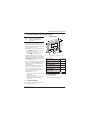
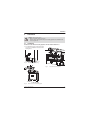
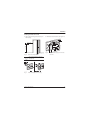
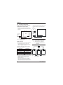
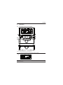
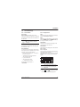
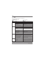
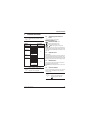
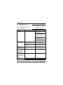
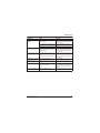
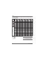
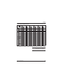
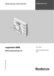
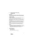
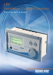
7719
Installation and Operating Instructions
002 506
Room temperature controller for
heating appliances with bus-enabled
Heatronic 3 and RT 10
TD 200
TEXT DISPLAY
TD
200
6 720 612 220-00.1R
6 720 612 220-00.1R
FOR WORCESTER HEATING APPLIANCES
WITH BUS-ENABLED HEATRONIC 3 AND RT 10
6 720 612 220 GB (05.09) OSW
Order no. 7 719 002 506
INSTALLATION,
USER INSTRUCTIONS &
CUSTOMER CARE GUIDE
Dear customer,
Congratulations on having decided in favour of a
top-quality product from our company.
The TD 200 offers everything you can expect
from a modern heating control: It is both reliable
and energy saving.
Like all Bosch Group products, the TD 200 has
been produced and tested according to the most
stringent quality standards so that you can enjoy
the WORCESTER warmth for a long time to
come.
2
6 720 612 220 GB (05.09)
Contents
Contents
1
1.1
1.2
1.3
2
Technical data for the accessory
item
Standard package
Technical data
Accessories
Regulations
5
5
5
5
5.6
5.6.1
5.6.2
5.6.3
General Settings
Time and Date
Display format
Key lock
23
23
23
23
6
INFO
24
7
7.1
7.2
7.3
7.4
7.5
7.6
EXPERT SETTINGS
EXPERT SETTINGS-Overview
Operating instructions in brief
System errors
Maintenance
Service address
System info
25
25
25
25
25
25
26
8
Service display
26
6
3
3.1
3.2
Installation
Installation
Electrical connections
7
7
10
4
4.1
4.2
11
11
13
9
General information
27
13
14
15
15
17
17
10
Troubleshooting
28
4.2.3
4.3
4.3.1
4.3.2
4.3.3
Operation
Operating elements and symbols
Change room temperature and
operating mode
Set room temperature time
restricted
Advance the next switching time
and associated operating mode to
the current time
Changing the operating mode
Use menu
Program
Delete settings
Reset factory settings
5
5.1
5.2
5.3
5.4
5.4.1
5.4.2
5.4.3
5.5
5.5.1
5.5.2
MAIN MENU
MAIN MENU-Overview
Operating instructions in brief
Holiday
Heating
Program
Heating levels
Optimum Start
Domestic Hot Water
Program
Circ. pump runs
18
18
19
19
20
20
21
21
22
22
22
11
11.1
11.2
11.3
11.3.1
11.3.2
Settings
MAIN MENU-Settings
EXPERT SETTINGS-Settings
Time Programs
Heating Program
Domestic Hot Water Program
30
30
31
32
32
33
4.2.1
4.2.2
6 720 612 220 GB (05.09)
13
Index
34
3
Safety precautions
Safety precautions
Symbols
B These instructions must be observed to
ensure correct operation.
Safety instructions in this
document are identified by a
warning-triangle symbol and are
printed on a grey background.
B Only have the accessories installed by an
authorised heating installer.
B Only use these accessories in conjunction
with the heating appliances listed. Observe
connection diagram!
B Never connect this accessory item to the
230 V mains electricity supply.
B Before assembling these accessories:
Interrupt voltage supply (230 V AC) to the
heating appliance and all additional devices
using the bus.
B For wall mounting: Do not mount these accessories in wet rooms.
Signal words indicate the seriousness of the hazard in terms of the consequences of not following
the safety instructions.
• Caution indicates that minor damage to
property could result.
• Warning indicates that minor personal injury
or serious damage to property could result.
• Danger indicates that serious personal injury
could result. In particularly serious cases, lives
could be at risk.
i
Notes are identified by the symbol shown on the left. They are
bordered by horizontal lines
above and below the text.
Notes contain important information in cases
where there is no risk of personal injury or damage to property.
4
6 720 612 220 GB (05.09)
Technical data for the accessory item
1
Technical data for the accessory item
i
The TD 200 can only be connected to a heating appliance
with bus-enabled Heatronic 3
circuit board.
• The TD 200 serves to display boiler and system information and for changing the displayed values. If the Service button is pressed
on the boiler, the TD 200 serves purely as a
display for the Service mode.
1.2
Technical data
35
134
145
119
• The TD 200 is a timer with time programs for:
– Heating : 7 day heating program with
6 switching times per day
– Hot water : 7 day hot water program
with 6 switching times per day
6 720 612 220-02.1R
• Room temperature control of an unmixed
heating circuit is possible in conjunction with
the RT 10. The TD 200 receives the current
room temperature via the temperature sensor integrated in the RT 10.
• If no RT 10 is connected, the TD 200 works
purely as a timer with On/Off function for the
time program without consideration of the
room temperature.
• The TD 200 has a battery power reserve of
approx. 20 months. If the TD 200 has not
received any power for longer than 20
months, the time and date are deleted. All
other settings are maintained.
• Installation options:
– In the heating appliance with bus-enabled
Heatronic 3
– With optional accessory:
Wall mounting with bus connection to the
heating appliance with bus-enabled
Heatronic 3
1.1
Fig. 1
Unit dimensions with base (accessory)
Nominal voltage
Bus supply
Nominal current (without
lighting)
Controller output
Permissible ambient
temperature
Class of protection
Type of protection:
- Installed in Heatronic 3
- Wall mounting
1.3
10...24 V DC
15 V DC
6 mA
2-wire bus
0 ... +50 ˚C
III
IPX2D
IP20
Accessories
• Base for wall mounting
• Room temperature controller RT 10 .
Standard package
TD 200 without wall mounting socket for installation in the heating appliance.
6 720 612 220 GB (05.09)
5
Regulations
2
Regulations
Related standards:
• BS EN60730-1:2001
• BS EN60730-2-7:1992
• Electro Magnetic Compatibility and Radio
Spectrum Matters (ERM); Short Range
Devices (SRD) ETSI
• EN300 220 1.
EC Directives:
• European Union Law Directive 2000/R4/EC
• Low Voltage Directive (73/23/EEC)
• Electro Magnetic Compatibility Directive
(89/336/EEC)
• CE Marking Directive (93/68/EEC).
6
6 720 612 220 GB (05.09)
Installation
3
Installation
Danger: risk of electric shock!
B Before assembling these accessories:
Interrupt voltage supply (230 V AC) to the heating appliance and all additional devices using the bus.
3.1
Installation
Installation of the TD 200 in heating appliance with bus-enabled Heatronic 3
B For a detailed description of the heating appliance parts, see installation instructions of the
heating device.
6 720 611 792-03.1R
Fig. 2
Remove the outer casing
2.
6 720 612 220-03.1R
Fig. 4
1.
Insert TD 200 in the guides
4.
Fig. 3
6 720 611 792-04.1R
3.
Remove cover and blanking plate
6 720 612 220 GB (05.09)
7
Installation
4.
3.
1.
Fig. 5
8
6 720 612 220-04.1R
2.
Lock TD 200 into place and replace
cover
6 720 612 220 GB (05.09)
Installation
Installing the TD 200 on the wall
B Use the wall mounting socket accessory for
wall mounting.
B Make electrical connections (see Figure 10).
3.
1,2 - 1,5m
min.
0,3m
1.
6 720 612 220-05.1R
Fig. 6
i
Select mounting location
Fig. 8
6 720 612 220-06.1R
2.
Locate TD 200 upper part and slide
into frame
The mounting surface on the wall
must be even.
3,5 mm
6 mm
6 mm
3,5 mm
6 720 612 220-07.1R
Fig. 7
Wall mounting socket accessory
6 720 612 220 GB (05.09)
9
Installation
3.2
Electrical connections
TD 200 in the heating appliance with busenabled Heatronic 3 circuit board
B Installation of the TD 200 automatically creates the bus connection via the three contacts
(Figure 4).
stations, radio and television appliances, amateur radio stations, microwave appliances
etc).
B
Heatronic 3
TD 200
Heatronic 3
RT 10
B
TD 200
RT 10
ST 19
B
B
B
A F 1
2
4 B B
B
6 720 612 220-09.1J
ST 19
A F 1
2
4
B
Fig. 10
B
TD 200 connected to the bus-enabled
Heatronic 3.
6 720 612 218-03.1J
TD 200 integrated in the bus-enabled
Heatronic 3.
If the cable cross sections of the
bus connections from the TD 200
and from the RT 10 to the bus-enabled Heatronic 3 are different:
i
TD 200 on the wall
B Bus connection from the TD 200 to additional
devices using in the bus (e. g. RT 10):
Use electrical cables corresponding to type
H05 VV-... (NYM-I...) minimum.
B Connect bus connections via a
junction box.
A
Permissible cable lengths of the bus-enabled
Heatronic 3 to the TD 200:
Cable length
Cross section
≤ 80 m
0.40 mm2
≤ 100 m
0.50 mm2
≤ 150 m
0.75 mm2
≤ 200 m
1.00 mm2
≤ 300 m
1.50 mm2
B To avoid inductive influences, lay all cables
carrying low voltage lines of 230 V or 400 V
separately (minimum spacing 100 mm).
B Shield the cables in the case of external
inductive influences.
This ensures that the cables are shielded
against external influences (e.g. heavy current
cables, overhead contact wires, transformer
10
2
2
2
B B
B B
B B
B
B
B
100 mm
Fig. 11
6 720 612 220-08.1J
Fig. 9
100 mm
Connection of the bus connections via
junction box (A)
6 720 612 220 GB (05.09)
Operation
4
Operation
4.1
Operating elements and symbols
9
12 h
15
18
6
3
21
24 h
c
menu
info
b
a
d
f
e
h
g
advance
advance
6 720 612 220-01.1O
Fig. 12
i
Standard display when connected RT 10
If no RT 10 is connected, this standard display appears as follows:
9
12 h
15
18
6
3
24 h
21
6 720 612 220-16.J
6 720 612 220 GB (05.09)
11
Operation
Operating elements
a
Turn selection knob
in the +
direction: Select upper Menu/Info
texts or set value higher
Turn selection knob
in the direction: Select bottom Menu/Info
texts or set value lower
Press selection knob
:
Open or save Menu/value
b
Operating mode switch:
Heating
Hot water
Automatic mode Automatic mode
Continuous
Continuous On
High or On
Continuous
Automatic mode
Low or Off
Continuous
Continuous Off
Frost
c
Button advance :
To advance the next switching time
and the associated operating mode
= High or On
= Low or Off
= Frost
for the heating to the current time.
d
Button advance :
To advance the next switching time
and the associated operating mode
On or Off for hot water heating to the
current time
e
Button info : Display values
f
Button menu : Open Menu
g
Button
:
Show previous menu level
h
Button
:
Delete/Reset value
i
12
In order to simplify this document,
the operating elements and operating modes will sometimes only
be identified by symbols, e.g.
or .
Symbols
9
21
15
3
+
ok
advance
advance
Current room temperature
(only with RT 10 )
Flashing segment:
current time from 09:30 until
09:45
Full segments:
Heating program current day for
= High or On
(1 Segment = 15 min)
Empty segments:
Heating program current day for
= Low or Off
(1 Segment = 15 min)
No segments:
Heating program current day for
= Frost (no segments)
Operating mode High or On for
heating
Operating mode Low or Off for
heating
Operating mode Frost or Off for
heating
Automatic mode for heating
Holiday program
Burner on
Upper Menu/Info texts or value
higher
Bottom Menu/Info texts or value
lower
Open or save Menu/value
Call up parent menu level
Delete/Reset value
Advance next switching time and
the associated operating mode
= High or On
= Low or Off
= Frost
for the heating to the current time.
Advance next switching time and
the associated operating mode On
or Off for hot water heating to the
current time.
6 720 612 220 GB (05.09)
Operation
4.2
Change room temperature and
operating mode
4.2.1
Set room temperature time
restricted
To permanently change the room temperature,
see Chapter 5.4.2 on page 21.
Without the RT 10 this function is not available.
If an RT 10 is connected and the standard display is displayed in Automatic mode :
B Set required room temperature with
.
The temperature setting is effective until the
next switching time. After this the room temperature set for the heating program is valid.
4.2.2
Advance the next switching time
and associated operating mode to
the current time
To permanently change the operating mode, see
Chapter 4.2.3 on page 14.
i
To cancel Heating Advance on:
B Press
advance
again.
Hot Water Advance
If the standard display is displayed in Automatic
mode or continuous economy is displayed:
B Press advance to advance the next switching
time and associated operating mode On or
Off for hot water heating to the current time
The display shows Hot Water Advance on
and the altered data.
If the next switching time of the hot water program is exceeded, Hot Water Advance on is
reset and Automatic mode is active again.
Hot Water Advance on Cancel in advance:
B Press advance again.
Use the function if there is no
longer a demand for heat or if the
home is to be left for a longer period or if an unexpected return to
the property occurs.
Heating Advance
If the standard display is displayed in Automatic
mode :
B Press advance to advance the next switching
time and associated operating mode
= High or On
= Low or Off
= Frost
for the heating to the current time.
The display shows Heating Advance on
and the altered data.
If the next switching time of the heating program is exceeded, Heating Advance on is
reset and Automatic mode is active again.
6 720 612 220 GB (05.09)
13
Operation
4.2.3
Changing the operating mode
Automatic mode
(default setting)
• Heating with RT 10:
Automatic change between High
/
Low / Frost corresponding to the heating program. The TD 200 controls the room
temperatures set in the submenu Heating
levels (see Chapter 5.4.2 on page 21).
• Heating without RT 10:
Automatic change between On
/ Off
corresponding to the heating program. During
On the flow temperature set on the heating
appliance is controlled.
• Hot water:
Automatic change On / Off corresponding to
the hot water program entered.
Continuous low mode
• Heating with RT 10:
The TD 200 continuously controls to the room
temperature set in the submenu Heating levels for Low
(see Chapter 5.4.2 on
page 21). The heating program is ignored.
• Heating without RT 10:
A continuous control to the flow temperature
which corresponds to the heating appliance
frost protection is performed. The heating program setting is ignored. The heating remains
switched off apart from the heating appliance
frost protection
• Hot water:
Automatic change On / Off corresponding to
the hot water program entered.
Continuous heating
• Heating with RT 10:
The TD 200 continuously controls to the room
temperature set in the submenu Heating levels for High
(see Chapter 5.4.2 on
page 21). The heating program is ignored.
• Heating without RT 10:
A continuous control to the flow temperature
set on the heating appliance is performed.
The heating program is ignored.
• Hot water with combination heating
appliance:
If the ECO button is not pressed on the heating appliance, hot water is immediately available. The hot water program is ignored.
• Domestic hot water storage tank:
Hot water is continuously controlled to the hot
water temperature set on the heating appliance. The hot water program is ignored.
14
Continuous frost protection
• Heating with RT 10:
The TD 200 continuously controls to the room
temperature set in the submenu Heating levels for Frost
(see Chapter 5.4.2 on
page 21). The heating program is ignored.
• Heating without RT 10:
A continuous control to the flow temperature
which corresponds to the heating appliance
frost protection is performed. The heating
remains switched off apart from the heating
appliance frost protection. The heating program is ignored.
• Hot water with combination heating
appliance:
Hot water is immediately available. The hot
water program is ignored.
• Domestic hot water storage tank:
The hot water can cool down to 10˚C. The hot
water program is ignored.
6 720 612 220 GB (05.09)
Operation
4.3
Use menu
4.3.1
Program
The programing steps are always carried out according to the same principle. The functions of the operating elements and the meaning of the symbols are described in
Chapter 4.1 from page 11, e.g. to enter a heating program, perform the following programming steps (example with RT 10 present).
i
Call up Main Menu
9
12 h
The segments for the heating program are only displayed if all
switching times for Mo - Fr are
the same.
i
B Press button menu .
The display lights up and the Main Menu is
shown.
15
9
12 h
15
18
6
18
6
3
24 h
21
6 720 612 220-10.1R
Fig. 13
3
Main Menu
Fig. 15
B Turn selection knob
until the the required
menu item is highlighted.
In the example: Select Heating.
B Press selection knob
to confirm the
selection.
The submenu is displayed.
12 h
21
6 720 612 220-12.1J
Select submenu
9
24 h
15
Submenu: Heating Program
B Turn selection knob
until the the required
menu item is highlighted.
In the example: Select Mo - Fr.
B Press selection knob
to confirm the
selection.
The next submenu with the pre-programmed
switching times and operating modes P1 to
P6 is displayed.
9
12 h
15
18
6
18
6
3
24 h
21
6 720 612 220-11.1R
Fig. 14
3
Submenu: Heating
B Turn selection knob
until the the required
menu item is highlighted.
In the example: Select Program.
24 h
21
6 720 612 220-13.1O
Fig. 16
Submenu: Heating Program Mo - Fr
B Press selection knob
to confirm the
selection.
The next submenu is displayed.
6 720 612 220 GB (05.09)
15
Operation
Set values
B Turn selection knob
until the the required
menu item is highlighted.
In the example: Select P1.
B Press selection knob
to confirm the
selection.
The switching time to be changed and the
associated segment flashes.
9
12 h
B Press selection knob
to save the operating mode.
The operating mode saved is also accepted
for the individual days Monday to Friday.
The setting for P1 is now complete. The
altered switching time, operating mode and
segments are displayed.
9
12 h
15
15
18
6
18
6
3
21
24 h
6 720 612 220-25.1O
3
24 h
Fig. 19
21
6 720 612 220-14.1J
Fig. 17
Submenu: Heating Program Mo - Fr
B Turn selection knob
to set the switching
time.
In the example: Set 05:30.
The associated segments change at the same
time.
B Press selection knob
to save the switching time.
The switching time saved is also accepted for
the individual days Monday to Friday.
The operating mode to be changed and the
segment of the new switching time flashes.
9
12 h
-orB Select menu level:
– Push button
or
– Turn selection knob
until the menu
item
back is highlighted and press the
selection button
to confirm the selection.
The parent menu is displayed.
End programming
B Press the
15
menu
button.
18
6
3
24 h
21
6 720 612 220-24.1O
Fig. 18
Submenu: Heating Program Mo - Fr
B Set further switching times and operating
modes P2 to P6 as described above.
Submenu: Heating Program Mo - Fr
i
This process can be repeated for
Saturday and Sunday programming and individual days.
B Turn selection knob
to set the operating
mode.
In the example: Set Low .
16
6 720 612 220 GB (05.09)
Operation
4.3.2
Reset all settings
Delete settings
Either overwrite the value for delete it using the
button
.
i
B Select the value to be deleted in the Menu.
In the example: Select P1.
If the standard display is set:
B Press the
button.
The deleted value flashes.
9
12 h
B Keep menu and
pressed at the same
time until the following warning text is displayed:
15
9
18
6
3
24 h
All personal settings are reset to
the default settings with this function.
12 h
15
18
6
21
6 720 612 220-17.1O
Fig. 20
Submenu: P1 deleted
3
B Press the selection knob
switching time.
to save the
B Press the menu button to return to the standard display.
4.3.3
Reset factory settings
24 h
21
6 720 612 220-19.1R
Fig. 22
Warning text: Total reset
B If you wish to perform the total reset:
menu
Continue to keep
pressed at the
same time until the following help text is displayed:
Reset a program
9
12 h
15
Example for resetting a heating program:
B Select the menu Heating > Program >
Reset to factory.
B Press the selection knob
selection.
to confirm the
to set Yes.
B Press the selection knob
to save the setting.
In the example Heating Program appears
when resetting this help text:
12 h
3
24 h
21
6 720 612 220-20.1R
Fig. 23
B Turn the selection knob
9
18
6
Help text: Total reset
All personal settings have been reset to the
factory setting.
B Press the selection knob
standard display.
to return to the
15
18
6
3
24 h
21
6 720 612 220-18.1R
Fig. 21
Help text: Reset to factory
B Press the selection knob
Menu.
6 720 612 220 GB (05.09)
to return to the
17
MAIN MENU
5
MAIN MENU
5.1
MAIN MENU-Overview
Submenu
MAIN MENU
back
Holiday
Heating
1.
back
Start
End
Heating level
Domest. hot water
back
Program
2.
3.
-
-
back
Mo - Fr
Sa - Su
All days
Monday, Tuesday ... Sunday
Heating levels1)
Domestic Hot Water
Optimum Start1)
back
Program
Reset to factory
back
High
Low
Frost
back
Mo - Fr
Sa - Su
All days
Monday, Tuesday ... Sunday
General Settings
Circ. pump runs
back
Time and Date
Display format
Key lock
1)
18
Reset to factory
back
Time
Date
Summer-/Wintertime
Time adjustment
back
Time
Date
Temperature
LCD contrast
-
Description
Page
19
back
P1, P2 ... P6
back
P1, P2 ... P6
back
P1, P2 ... P6
back
P1, P2 ... P6
-
21
21
back
P1, P2 ... P6
back
P1, P2 ... P6
back
P1, P2 ... P6
back
P1, P2 ... P6
-
-
20
22
22
23
23
23
Heating with RT 10
6 720 612 220 GB (05.09)
MAIN MENU
Factory settings, setting range and personal settings:
Chapter 11 from page 30.
i
5.2
menu
Operating instructions in
brief
: MAIN MENU open/close
: Select submenu/Set value
: Open submenu/Save value
or
back: Call up parent menu level
Navigation in the menu structure, programming,
deleting values and resetting back to the factory
settings are described in detail in Chapter 4.3 on
page 15.
5.3
Holiday
The Holiday program controls the heating and
hot water heating for the operating mode set in
the holiday program (frost protection is ensured).
• Holiday > Start:
– If the date for Start is today, the Holiday
program starts immediately.
– If the date for Start is from tomorrow or
later, the Holiday program starts at 00:00
(= 12:00 am) on the day set.
• Holiday > End:
The Holiday program ends at
23:59 (= 11:59 pm) on the day set
• Holiday > Heating level:
Operating mode for the heating during the
Holiday program
• Holiday > Domest. hot water:
Operating mode for the hot water during the
Holiday program.
If the Holiday program is active, the following will
appear for example:
9
12 h
15
18
6
3
24 h
21
6 720 612 220-26.1O
Fig. 24
Holiday active
Cancel Holiday mode in advance:
B Select Menu Holiday > Start and press
.
The display shows --:--:----.
B Press the selection knob
ting.
6 720 612 220 GB (05.09)
to save the set-
19
MAIN MENU
5.4
i
5.4.1
Heating
Set the flow temperature controller on the heating appliance to
the maximum inlet temperature
required.
Program
Default setting (Automatic mode)
Heating with RT 10:
• Automatic change between High
/
Low
/ Frost corresponding to the heating program entered.
• Operating mode High :
The TD 200 controls to the room temperature
set for the the operating mode High.
• Operating mode Low :
The TD 200 controls to the room temperature
set for the the operating mode Low.
• Operating mode Frost :
The TD 200 controls to the room temperature
set for the the operating mode Frost.
Heating without RT 10:
• Automatic change between heating On
/
Off corresponding to the heating program
entered.
• Operating mode On :
The heating appliance controls to the flow
temperature set.
• Operating mode Off :
The heating appliance controls to the flow
temperature which corresponds to the heating appliance frost protection.
20
Setting options
• Heating with RT 10: Maximum six switching
times per day with three different operating
modes (High / Low / Frost).
• Heating without RT 10: Maximum six
switching times per day with two different
operating modes (On / Off).
• optionally the same times for each day, Monday - Friday, Saturday - Sunday or different
times for each day
• optionally different times for each day or the
same times for:
– Each day (All days)
– Monday to Friday (Mo - Fr)
– Saturday and Sunday (Sa - Su)
• shortest switching period is 15 minutes
(= 1 Segment).
Set switching times and operating mode
i
Deactivate unrequired switching
times by deleting them.
• Mo - Fr: Begin Monday to Friday at the same
time with the selected operating mode.
• Sa - Sun: Begin Saturday and Sunday at the
same time with the selected operating mode.
• All days: Begin each day at the same time
with the selected operating mode.
• individual week day (e.g. Thursday): Begin
each Thursday at the same time with the
selected operating mode.
• Reset to factory: Reset switching times and
operating modes, see Chapter 4.3.3 on
page 17.
6 720 612 220 GB (05.09)
MAIN MENU
If the programming for e.g. Thursday differs from the remaining
week days, the selection will display All days and Mo - Fr for all
values ----- from --:--. i.e. there
are no joint switching times and
operating modes for this selection.
i
If the switching times and operating modes are
not to be changed, skip this with
or
.
5.4.2
Heating levels
Heating levels is only available if a RT 10 is
connected.
For each operating mode (High / Low / Frost)
the required room temperature can be set here.
5.4.3
Optimum Start
Optimum Start is only available if a RT 10 is
connected and the heating program is in Automatic mode. This function can be switched on
and off at the TD 200.
Optimum Start delays the heating start after
low phase.
To enable the required room temperature to be
attained approx. 1 hour after the programmed
switching time High , the TD 200 calculates
the optimum time point for the heating start.
Example:
• required room temperature: 21˚C
• current room temperature: 16˚C
• Factor for room heating: 1 K in 10 minutes.
To reach the required room temperature, the
heating requires 50 minutes on account of the
5 K difference. It is therefore only 10 minutes
after the programmed switching time High
that the heating starts.
6 720 612 220 GB (05.09)
21
MAIN MENU
5.5
Domestic Hot Water
B Set the required hot water temperature on the
heating appliance.
The heating appliance ensures frost protection.
For a hot water storage tank with its own temperature control:
B Set the required hot water temperature at the
hot water storage tank.
Frost protection is only ensured during the
operating mode hot water On.
5.5.1
Program
• Automatic change between hot water On /
Off corresponding to the hot water program
entered.
• On: The heating appliance controls to the hot
water temperature set.
– For a combination appliance: If the ECO
button is not pressed on the heating appliance, hot water is immediately available.
– For a heating system with hot water storage tank: Depending on the tank size and
the hot water consumption, one tank filling
per day is often sufficient (e.g. before the
first or after the last heating phase of the
day).
• Off: The heating appliance controls to approx.
10˚C water temperature which corresponds
to the heating appliance frost protection.
– For a combination appliance: The heat
exchanger inside the heating appliance
does not remain heated, as a result hot
water is not available until after a longer
period of drawing off the hot water.
– For a heating system with hot water storage tank: After a successful tank filling during hot water On, hot water remains
available to a limited degree.
22
Setting options
• Maximum six switching times per day with two
different operating modes (On / Off).
• optionally the same times for each day or different times for each day
• shortest switching period is 15 minutes
(= 1 segment).
Set switching times and operating mode
i
Deactivate unrequired switching
times by deleting them.
Week days, switching times and associated
operating modes (On / Off), as described in
detail in Chapter 5.4 on page 20.
5.5.2
i
Circ. pump runs
If no circulation pump is present,
the setting in the Menu Circ.
pump runs has no effect.
This function defines the number of circulation
pump starts per hour during the hot water On
phase. With the setting:
• 0/h the circulation pump always remains inactive.
• 1/h to 6/h the circulation pump remains in
operation at each start for 3 minutes.
• 7/h the circulation pump operates continuously during the hot water On phase.
During the hot water Off phases the circulation
pump remains inactive.
6 720 612 220 GB (05.09)
MAIN MENU
5.6
General Settings
5.6.1
Time and Date
5.6.2
Display format
Time / Date
Time
Time and Date are already set ex works.
The format for the time display can be selected
between 12h am/pm or 24h here.
If the power supply for the TD 200 is interrupted
for longer than 20 months, the time and date can
be reset here.
i
The current day of the week (e.g.
Mo) is automatically calculated
via the date.
Date
The format for the date display can be selected
between MM.DD.YYYY or DD.MM.YYYY here
(D = Day, M = Month, Y = Year).
Temperature
Summer-/Wintertime
The format for the temperature display can be
selected between ˚C or ˚F here.
The automatic summer/winter time setting can
be switched on or off.
LCD contrast
Time adjustment
The contrast for the display can be set between
25% and 75% .
A corrective factor can be set for the time here.
This corrective factor is applied once per week.
5.6.3
Ascertain corrective factor, example:
• The time deviates by approx. –3 minutes in
the course of a year.
• –3 minutes in the year correspond to
–180 seconds in the year
Key lock
The key functions can be locked against inadvertent or unauthorised activation.
If Key Lock is active and a locked key is pressed
during the standard display, the following will
appear:
9
12 h
15
• 1 year has 52 weeks
• –180 seconds: 52 weeks
= –3.46 seconds per week.
The requisite corrective factor is
+3.5 s/week.
18
6
3
24 h
21
6 720 612 220-21.1R
Fig. 25
i
Help text: Key lock active
The settings changed will only become active after deactivating the
Key Lock .
Deactivate the lock for the key functions:
B Keep advance and advance pressed at the same
time until the standard display appears.
6 720 612 220 GB (05.09)
23
INFO
6
INFO
Various system information messages can be displayed here.
Operating instructions in brief
info
: INFO open/close
: Open submenu:
: Select submenu/info texts
or
INFO
back
Boiler
Information
System
Information
Domestic Hot
Water
Service
Instructions
24
Display text
back: Call up parent menu level
Description
back
Burner
Indicates whether the burner is switched on or off
On / Off
Pump
Indicates whether the pump in the heating appliance is
On / Off
switched on or off
Max. flow temperature
Maximum flow temperature set at the heating appliance
75.0˚C
Max. domestic hot water temperature
Maximum hot water temperature set at the heating appli60.0˚C
ance
back
RT 10 connected
Indicates whether a RT 10 is present
Yes / No
Optimum start
Indicates whether Optimum Start is switched on or off (only
On / Off
with RT 10)
Operation Mode
Current operating mode or special mode for the heating
Auto-high / Auto-low / Auto-frost / Auto-on / Autooff / High / Low / Frost / On / Off / Holiday-high /
Holiday-low / Holiday-frost / Holiday-on / Holiday-off
Requested room temperature
Room temperature requested by the RT 10 (only with
25.0˚C
RT 10)
Actual room temperature
Room temperature measured at the RT 10 (only with
22.0˚C
RT 10)
Requested flow temperature
Requested flow temperature
75.0˚C
Actual flow temperature
Flow temperature measured at the heating appliance
47.0˚C
back
Operation mode
Current operating mode or special mode for the hot water
Auto-on / Auto-off / On / Off / Holiday-on /
Holiday-off
Requested domestic hot water temperature
Hot water temperature requested by the TD 200
60.0˚C
Actual domestic hot water temperature
Hot water temperature measured at the heating appliance
40.0˚C
Domestic hot water request status
State of the hot water heating
Active / Passive
back
Worcester hotline
Hotline telephone number of the heating appliance manuTelephone number
facturer
Service telephone
Service telephone number of the specialist heating comTelephone number
pany (system manufacturer)
Service address
Service address of the specialist heating company (system
Heating company Ltd.
manufacturer)
back
Set new...
Operating Instructions
6 720 612 220 GB (05.09)
EXPERT SETTINGS
7
EXPERT SETTINGS
The menu EXPERT SETTINGS is
intended for the specialist / installer!
i
7.1
EXPERT SETTINGS-Overview
EXPERT
SETTINGS
back
System errors
Submenu
Service
address
System info
i
menu
(press approx. 3 seconds):
EXPERT SETTINGS open
menu
: EXPERT SETTINGS close
: Select submenu/Set value
: Open submenu/Save value
or
back
back
Next maintenance
Interval
Confirm
maintenance
back
Telephone number
Name
back
Installation date
Type and number
Software version
Manufacturing
date
RT 10 equipped?
Operating instructions in
brief
Description
Page
25
7.3
System errors
Fault history
The expert can have the last 10 faults which may
have occurred displayed here (error date, code
and description). The first fault displayed can still
be active. The further faults are no longer active.
26
Factory settings, setting range
and settings for the expert:
Chapter 11 from page 30
7.4
Maintenance
The expert can set and activate the interval for
the requisite maintenance here.
0 months means that the function is not available.
7.5
Service address
In case of servicing the expert can enter the telephone number and address of the specialist
company here.
i
6 720 612 220 GB (05.09)
back: Call up parent menu level
Navigation in the menu structure, programming,
deleting values and resetting back to the factory
settings are described in detail in Chapter 4.3 on
page 15.
Maintenance
7.2
Enter spaces:
B If the current character has a
dark background, skip with
.
25
Service display
7.6
System info
The expert can display various system information messages here:
• Installation date (automatically becomes
active on commissioning)
• Type number (fixed value)
• Software version (fixed value)
• Manufacturing date (fixed value)
• RT 10 equipped? Yes / No (is automatically
set on commissioning with RT 10 to Yes).
i
26
8
Service display
If the Service button is pressed on the heating
appliance and the Service mode is active, the following display typically appears instead of the
Service display:
Service 1.A:
set maximum central
heating heatout
No programming is possible when the Service
mode is active. Only the operating mode can be
changed via the operating mode switch.
If the RT 10 is removed: Set
B RT 10 equipped? to No.
6 720 612 220 GB (05.09)
General information
9
General information
... Notes on saving energy:
• The temperature in the room where the RT 10
is installed acts as a guide parameter for the
entire heating network. As a result, the power
of the radiators must be set as low as possible, using thermostatic radiator valves.
• Control the temperature in the adjoining
rooms via thermostatic radiator valves.
• Heat from other sources in the room (e.g. sunshine etc.) can lead to the heating in the
adjoining rooms remaining too low.
• A significant amount of energy can be saved
by lowering the room temperature. A reduction in temperature by 1 K (˚C) can result in
up to 5 % energy saving.
• Good thermal insulation of the building: The
set low temperature level is not reached.
Energy is therefore saved, as the heating
remains switched off.
• Do not keep windows open on vent setting to
ventilate. This would continuously cool down
the room without significantly improving the
air in the room.
• Ventilate fully for a short time (completely
open windows).
• Turn the thermostatic valve during ventilation
or switch to low setting.
6 720 612 220 GB (05.09)
27
Troubleshooting
10
Troubleshooting
Faults in the devices using the bus are displayed.
A fault in the heating appliance is shown in the
display with corresponding help texts.
i
For the expert:
B Rectify the fault in accordance
with the heating appliance
documentation.
B Contact a heating expert.
Display
Cause
RT 10 defect
Temperature sensor in the RT 10
defective
No Bus communication
On / Off
instead of
Room temperature
Only Service modes are
displayed, e.g.:
Service 1.A:
set maximum central
heating heatout
The following appears
each time the button is
pressed:
press ok to go back
Key lock function is
active...
No display
28
Remedy
Emergency mode:
The heating automatically goes into
On / Off mode.
If Room temperature continues to
be displayed during the standard
display:
Set RT 10 equipped? to No (see
System info on page 26).
Have the bus connection checked
and, if necessary, the interruption
rectified by a professional.
Have RT 10 replaced by a professional.
The RT 10 using the bus no longer Have the bus connection checked
responds.
and, if necessary, the interruption
rectified by a professional.
Heating appliance using the bus no Have the bus connection checked
longer responds.
and, if necessary, the interruption
rectified by a professional.
RT 10 not detected during commis- RT 10 equipped? to Yes (see Syssioning. Set
tem info on page 26).
No error:
Service mode at heating appliance
active.
Press the Service button on the
heating appliance.
Key lock is active.
Deactivate key lock (see Key Lock
on page 23).
Heating appliance is switched off.
A “YS Plan” is connected.
Switch on heating appliance.
No function for TD 200 possible.
6 720 612 220 GB (05.09)
Troubleshooting
Complaint
Cause
Required temperature not Thermostat valve(s) in the control
reached
room set to low
Flow temperature controller on the
heating appliance set too low
Air lock in the heating system
Required room tempera- Installation location of the RT 10 not
ture is greatly exceeded suitable, e.g. outer wall, proximity to
window, draught, ...
Remedy
Fully open the thermostat valve(s)
or have an expert replace them with
manual valve(s).
Set flow temperature controller
higher.
Vent radiator and heating system.
Choose a better installation location
for RT 10 and have it moved by an
expert (see Installation Instructions
of the RT 10).
Choose a better installation location
for RT 10 and have it moved by an
expert (see Installation Instructions
of the RT 10).
Check setting.
Excessive room tempera- Temporary effect of heat from other
ture fluctuations
sources on the room, e.g. from sunshine, room lighting, TV, fireplace
etc.
Temperature rise instead Time of day incorrectly set
of fall
Room temperature too
Building has high degree of heat
Select Economy mode earlier.
high in Economy mode storage
Incorrect or no control
Bus connection defective for the
Have the bus connection checked
devices using the bus
and, if necessary, rectified by an
expert according to the connection
diagram.
Only Automatic mode can Operating switch defective
Have TD 200 replaced by a profesbe set
sional.
6 720 612 220 GB (05.09)
29
Settings
11
Settings
The factory settings, setting range and personal settings are summarised here.
11.1 MAIN MENU-Settings
MAIN MENU
Holiday > Start
Factory setting
--.--.----
Holiday > End
--.--.----
Holiday > Heating level
Low1)
Off2)
Off
Holiday > Domest. hot water
Heating > Program
Heating > Heating level > High1)
20.0˚C
Heating > Heating level > Low1)
16.0˚C
Heating > Heating level > Frost1)
7.0˚C
Heating > Optimum Start1)
Domestic Hot Water > Program
Domestic Hot Water > Circ. pump
runs
General Settings > Time and Date >
Time
General Settings > Time and Date >
Date
General Settings > Time and Date >
Summer-/Wintertime
General Settings > Time and Date >
Time adjustment
General Settings > Display Format >
Time
General Settings > Display Format >
Date
General Settings > Display Format >
Temperature
General Settings > Display Format >
LCD contrast
General Settings > Key Lock
Off
1)
2)
30
4/h
current time
current date
Yes
0,0 s/week
Personal
Setting range
settings
Today ... 12.31.2099
(in year/month/day increments)
Start date ... 12.31.2099
(in year/month/day increments)
Low / Frost / High1)
Off / On2)
Off / On
see table on page 32
5.0˚C ... 30˚C
(not lower than Low;
in 0.5-K increments)
˚C
5.0˚C ... 30˚C
(not lower than Frost and not higher
than High; in 0.5-K increments)
˚C
5.0˚C ... 30˚C
(not higher than Low;
in 0.5-K increments)
˚C
Off / On
see table on page 33
0/h ... 7/h (in 1/h increments)
current time
(in hour/minute increments and am/pm)
current date
(in year/month/day increments)
Yes / No
24 h
–60 s/week ... +60 s/week
(in 0.5 s/week increments)
12h am/pm or 24h
DD.MM.YYYY
MM.DD.YYYY or DD.MM.YYYY
˚C
˚C / °F
corresponding to
factory test
Off
25% ... 75%
s/week
%
Off / On
Heating with RT 10
Heating without RT 10
6 720 612 220 GB (05.09)
Settings
11.2 EXPERT SETTINGS-Settings
Factory setting Setting range
-
Setting by
an expert
-
-
-
-
-
-
-
0...120 months
Yes
0 months
(= Function off)
No
Yes / No
012345 6789
-
max. 20 characters
Service address
> Name
ABCD
-
max. 20 characters
System info
> Installation date
System info
> Type number
System info
> Software version
System info
> Manufacturing date
System info
> RT 10 equipped?
22.10.2005
Activation on
commissioning
Fixed value ex
works
Fixed value ex
works
Fixed value ex
works
No
-
-
-
-
-
-
-
-
EXPERT SETTINGS
System errors
Maintenance
> Next maintenance
Maintenance
> Interval
Maintenance
> Confirmation
maintenance
Service address
> Telephone number
6 720 612 220 GB (05.09)
Display example
01.01.2005
05 Pump motor
(current fault)
09.25.2004
14 Temp. Sensor
(up to max. 9 previous
faults)
22.10.2005
12 months
TD 200
7 777 777 777
JF11.12
27.06.2005
Yes
months
Yes / No
(is automatically set
to Yes on commissioning with RT 10)
31
Settings
11.3 Time Programs
11.3.1 Heating Program
with RT 10
without RT 10
Factory setting
P1
P2
P3
P4
P5
P6
˚C
t
˚C
t
˚C
t
˚C
t
˚C
t
˚C
t
Mo - Fr
20
06:30
16
08:30
20
16:30
7
22:30
-
-
-
-
Sa - Su
20
07:00
16
09:00
20
16:00
7
23:00
-
-
-
-
All days
-
-
-
-
-
-
-
-
-
-
-
-
Mo - Fr
On
06:30
Off
08:30
On
16:30
Off
22:30
-
-
-
-
Sa - Su
On
07:00
Off
09:00
On
16:00
Off
23:00
-
-
-
-
All days
-
-
-
-
-
-
-
-
-
-
-
-
i
Switching points P5 and P6 can
be defined by the user in addition
to the other settings as required.
Mo - Fr
Sa - Su
Personal settings
All days
Monday
Tuesday
Wednesday
Thursday
Friday
Saturday
Sunday
Factory settings with RT 10 in the Menu
Heating levels:
20˚C =
High
16˚C =
Low
7˚C =
Frost
32
6 720 612 220 GB (05.09)
Settings
11.3.2 Domestic Hot Water Program
Factory setting
P1
P2
P3
P4
P5
P6
˚C
t
˚C
t
˚C
t
˚C
t
˚C
t
˚C
t
Mo - Fr
On
06:30
Off
08:30
On
16:30
Off
22:30
-
-
-
-
Sa - Su
On
07:00
Off
09:00
On
16:00
Off
23:00
-
-
-
-
All days
-
-
-
-
-
-
-
-
-
-
-
-
Mo - Fr
Sa - Su
Personal settings
All days
Monday
Tuesday
Wednesday
Thursday
Friday
Saturday
Sunday
i
6 720 612 220 GB (05.09)
Switching points P5 and P6 can
be defined by the user in addition
to the other settings as required.
33
Settings
Index
A
Accessories ..............................................................5
L
Locking the key functions ....................................23
B
Battery power reserve ............................................5
M
Main menu ..............................................................18
- Domestic hot water .........................................22
- General settings ..............................................23
- Heating ...............................................................20
- Holiday ...............................................................19
- Operating instrcutions in brief ......................19
- Overview ............................................................18
C
Changing format for date .................................... 23
Changing format for temperature ..................... 23
Changing format for time .................................... 23
Changing LCD contrast ...................................... 23
Changing the operating mode ........................... 14
- Automatic mode (default setting) ................ 14
- Continuous frost protection .......................... 14
- Continuous heating ........................................ 14
- Continuous low mode .................................... 14
D
Deactivating the lock for the key functions ..... 23
Delete settings ...................................................... 17
E
Electrical connections ......................................... 10
- TD 200 in the heating appliance ................. 10
- TD 200 on the wall ......................................... 10
Expert settings ...................................................... 25
- Maintenance ..................................................... 25
- Operating instrcutions in brief ..................... 25
- Overview ........................................................... 25
- Service address ............................................... 25
- System errors ................................................... 25
- System info ....................................................... 26
N
Notes on saving energy .......................................27
O
Operation ................................................................11
- Change room temperature and
operating mode ................................................13
- Elements and symbols ....................................11
- Use menu ..........................................................15
Call up Main Menu .....................................15
End programming .......................................16
Select submenu ..........................................15
Set values ....................................................16
R
Reset factory settings ..........................................17
- Reset a program ..............................................17
- Reset all settings .............................................17
Room temperature controller
(see heating program) ........................... 14, 20, 22
G
Greenwich time format ........................................ 23
H
Heating appliance (settings) .............................. 20
I
Installation .................................................................7
- Assembly ..............................................................7
34
6 720 612 220 GB (05.09)
Settings
S
Safety precautions ..................................................4
Service display ...................................................... 26
Setting a corrective factor for time ................... 23
Setting summer-/wintertime ............................... 23
Settings
- Expert settings ................................................. 31
- Main Menu ........................................................ 30
- Time programs (tables)................................... 32
Domestic hot water program .................. 33
Heating program ........................................ 32
Specifications for room temperature
controller
- Accessories .........................................................5
- Standard package .............................................5
- Technical data .....................................................5
Standard package ...................................................5
Summary of factory settings, setting ranges
and personal settings .......................................... 30
T
Technical data ..........................................................5
Trouble shooting ................................................... 28
V
Various system information - info ...................... 24
6 720 612 220 GB (05.09)
35
Settings
INSTALLATION,
USER INSTRUCTIONS &
CUSTOMER CARE GUIDE
Worcester, Bosch Group
Cotswold Way, Warndon, Worcester WR4 9SW.
Tel. 01905 754624 Fax. 01905 754619
www.worcester-bosch.co.uk
Worcester Bosch Group is a trading name of
BBT Thermotechnology UK Ltd.
6 720 612 220 (05/09) OSW
36
6 720 612 220 GB (05.09)