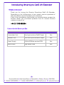
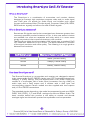
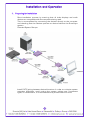
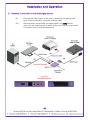
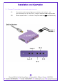
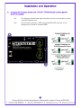
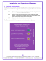
1
SLX-100
transmitter & receiver pair
user guide
also available:
SLX-111, SLX-214
for more information visit our website, or talk to one of our technical team
tel: +44 (0) 1306 628264, www.smart-e.co.uk
Notice
The information contained in this document is subject to change without
notice. Smart-e makes no warranty of any kind with regard to this
material, including but not limited to, implied warranties of
merchantability and fitness for particular purpose.
Smart-e will not be liable for errors contained herein or for incidental or
consequential damages in connection with the furnishing, performance
or use of this material.
No part of this document may be photocopied, reproduced, or
translated into another language without prior written consent from
Smart-e (UK) Ltd.
Edition 2, August 2008
Copyright 2008 Smart-e (UK) Ltd.
Table of Contents
Introducing SmartLynx
What ‘s in the box ..........................................................................................1
What is SmartLynx .........................................................................................2
Why is SmartLynx necessary ....................................................................2
How does SmartLynx work .........................................................................2
Installation and Operation
Transmitter .........................................................................................................3
Receiver ................................................................................................................8
Appendix
Specifications .....................................................................................................11
Troubleshooting ................................................................................................12
Limited warranty statement.......................................................................13
Partial Product List ............................................................................................ Back
Introducing SmartLynx Cat5 AV Extender
What‘s in the box?
Thank you for buying the Smart-e SmartLynx Cat5 AV Extender.
Depending on the configuration of your system various quantities of
the parts below may be included in your shipment.
If any of the accessories listed below are missing please contact the
Smart-e dealer you purchased products from or contact Smart-e
customer support at:
+44 (0) 1306 628264
If you ordered a SmartLynx Set:
SLX-100
Item
Description
Transmitter Unit
One Input and one Cat5 Output
Yes
Receiver Unit
One Cat5 Input and one Output
Yes
Power Supply
24Volt 20Watt earthed PSU
Yes
Mains Cable
Fig8 Mains Lead
Yes
-1-
Introducing SmartLynx Cat5 AV Extender
What is SmartLynx?
The SmartLynx is a combination of transmitter and receiver devices
designed to transmit high resolution computer video and/or audio signal
over Cat5 wire. AV stands for Audio Visual and includes such signal
formats as Broadcast Video (TV video signal), Computer Video (VGA, SVGA,
SXGA and etc. signals) and various formats of Audio signals.
Why is SmartLynx necessary?
Sometimes AV signals need to be transmitted over distances greater than
commonly specified product limitations of 5m. In this case several choices
are available, but most are expensive and bulky, which is in some cases
simply not practical, due to space limitations in the conduits.
The SmartLynx allows the transmission of AV signals over a standard Cat5
UTP cable over distances of up to 300m. The actual distance is a function
of the signal resolution and cable quality. The following is a rough guide to
distance and resolution:
Cat5 Cable Length
Maximum Recommended Resolution
200m
UXGA (1600x1200)
200m
1080p (1920x1080)
300m
SXGA (1280x1024)
How does SmartLynx work?
The Smart-e SmartLynx is a transmitter and receiver pair designed to extend
video, stereo audio and IR/RS232 signals over (UTP) unshielded twisted pair
category 5 (Cat5) cabling. They are supplied with a UK power supply and
consist of: a transmitter with a video input (connectors vary by model), an
audio input and a Cat5 output and; a receiver with a cat5 input and
corresponding outputs. Certain models are also supplied with local outputs
and/or IR or RS232 connections.
The extended signals depends on the model but supported signals are UXGA,
CVBS, YUV (YPbPr), Y/C and RGsB analogue format and Stereo Audio. The
basic concept behind this product is the ability to encode and decode
analogue signal combined with precise line equalization and compensation.
-2-
Installation and Operation
1. Preparing for installation
Start installation process by ensuring that all video displays and audio
devices are compatible with the computers being used.
This is accomplished by connecting the devices directly to the computer
and checking that the devices operate as desired without the SmartLynx
system.
Potential System Set-ups:
Install CAT-5 wiring between desired locations. In order to minimize system
operation difficulties, avoid routing the system cables near fluorescent
lights, air conditioners, or machines that may create electrical noise.
-3-
Installation and Operation
2. Connect Transmitter to the video signal source
2.1
Connect the video output of the source device to the appropriate
input of the transmitter using the relevant cable.
2.2
Although there are multiple connector types, only ONE feed of
video may be routed by the product at any one time, the multitude of
connectors are to simplify installations.
-4-
Installation and Operation
3. Connect Transmitter to the audio signal source
3.1
Connect the audio output of the source device to the ‘audio in’ mini
jack connectors on the SLX-TX111, using an interface cable if appropriate.
3.2
Either inputs ‘Audio 1’ or ‘Audio 2’ may be used but NOT simultaneously.
-5-
Installation and Operation
4. Jumpers on the base of the unit - DO NOT TOUCH when used as part of
SLX-100 system
4.1
The diagram below illustrates how the jumpers must be set for each
required video format.
4.2
Unit will come preset to VGA, as the SLX-RX100 receiver is not
designed to be able to receive RGBS.
-6-
Installation and Operation
5. System Power up
5.1
Turn the system on by plugging in the power adapter to the
SmartLynx Transmitter (or Receiver if preferred)
5.2
Power up your computer.
5.3
Observe both transmitter and receiver power LED are ON,
and source device is switched on.
6. Preparing and connecting System CAT-5 cable
The SmartLynx utilizes category 5 (CAT 5), unshielded twisted pair (UTP) cable to
transport signal between transmitter and receiver.
CAT 5 cable is more desirable than coaxial cable due to its low cost and ease of
installation. This cable is used for LAN applications and is found in abundance,
already installed, in many buildings . The category 5 is a standard which
establishes minimum requirements for telecommunications cabling within a
commercial building. The standard covers various aspects of wiring including
telecommunications outlets.
Following is the wiring standard for terminating CAT 5 cable using RJ 45
connector:
Pair 1
Pair 2
Pair 3
Pair 4
Pins 1 & 2
Pins 3 & 6
Pins 4 & 5
Pins 7 & 8
Connectors:
Capacitance:
Conductor Gauge:
Impedance:
RJ-45
14 pf/ft (46.2 pf/m)
24 AWG
100 +/- 15 ohms
4 - Pair
-7-
Installation and Operation of Receiver
1. Connecting SLX-RX100 to the display device
1.1
Making sure that the Cat 5 cable is connected to the SLX-TX111
transmitter output, connect the cable to the RJ45 socket on
the receiver unit.
1.2
If the cable connection is correct the power LED on the front of the
receiver should illuminate (power is sent up the Cat 5 cable).
1.3
Connect the display to relevant connector on the receiver
(see diagram below) using the appropriate cable.
-8-
Installation and Operation of Receiver
2.
Setting the cable length dials
The Receiver unit is preset for approximately 50m which is sufficiently accurate for most
applications. However if the image does not look sharp enough then follow the instructions
below
2.1
Whilst looking at an image on the display, preferably a long horizontal
bar, adjust the CABLE COMPENSATION dial.
2.2
Looking at the right-hand edge of the bar you will see the image
change. A highlighting bright edge means over compensation, whilst
a blurred dark edge means under compensation.
2.3
Adjust the dial until both effect are neutralized.
The Contrast control dial is factory pre-set and usually needs no adjustment.
-9-
Installation and Operation of Receiver
3.
Sync Processing
For VGA applications the Transmitter adds the Horizontal and Vertical Sync Pulses to
the Blue and Red channels. However, since the unit has been designed for use with
other types of video the Receiver provides the ability to pass both the Red and Blue
channels transparently or process them to remove the Sync Pulses.
3.1
For composite, y/c and YPbPr (component) the jumpers must be
set in the Video position.
3.2
For VGA the jumpers must be set in the VGA position.
The example below shows the jumpers set for composite, s-video or component
-10-
Technical Information
SLX-100
Video Input
Signal Type - Connector………….. UXGA-HD15/YUV/YPbPr - 3xRCA/YC - 4pin minidin
Bandwidth………………………………….. 400MHz
Impedance…………………………………. 75 Ohm
Audio Input
Signal Type…………………………………. Stereo Audio
Bandwidth………………………………….. 20kHz, 0dB
Impedance…………………………………. 10k Ohm
Connector………………………………….. 3.5mm minijack socket
Video Output
Signal Type - Connector………….. UXGA/YUV/YPbPr/YC/composite phono
Bandwidth………………………………….. 400MHz
Impedance…………………………………. 75 Ohm
Audio Output
Signal Type…………………………………. Stereo Audio
Bandwidth………………………………….. 20kHz, 0dB
Impedance…………………………………. 100 Ohm
Connector………………………………….. 3.5mm minijack socket
Power
Requirement - Connector……….. 24VDC 500mA - 5mm x 2.1mm
Dimensions
Size……………..……………………………….. 90 x 80 x 21 mm
Weight...……………………………………... 0.2kg
-11-
Troubleshooting
No video?
1)
2)
3)
Are the green LEDs on both the transmitter and receiver units? If not check that
the 24V power supply (PSU) is connected and the LED on the PSU is lit. Check the
cable compensation dials on the underside of the unit. Over compensation of the
Red and Blue channels can cause the display to misinterpret the sync pulses and
not display an image.
Is the video source a laptop or floating? (a floating source is one which has no
earth reference i.e. uses a double insulated PSU or a figure 8 mains cable). If so
make sure the PSU is an earthed unit when not using the PSU supplied.
Is the audio input level too high? The audio level should be set to line level (0dB or
700mV peak to peak) to prevent interference.
Display has problems syncing?
1)
Is the audio input level too high? The audio level should be set to line level (0dB or
700mV peak to peak) to prevent interference.
-12-
Appendix
Limited Warranty Statement
A.
Extent of limited warranty
1.
2.
3.
4.
5.
6.
Smart-e (UK) Ltd warrants to the end-user customers that Smart-e
product specified above will be free from defects in materials and
workmanship for the duration of 1 year, which duration begins on the
date of purchase by the customer. Customer is responsible for
maintaining proof of date of purchase.
Smart-e warranty covers only those defects which arise as a result of
normal use of the product, and do not apply to any:
a. Improper or inadequate maintenance or modifications
b. Operations outside product specifications
c. Mechanical abuse and exposure to severe conditions
If Smart-e receives during applicable warranty period notice of defect,
Smart-e will at its discretion replace or repair defective product . If
Smart-e is unable to replace or repair defective product covered by the
Smart-e warranty within reasonable period of time Smart-e shall refund
the cost of the product.
Smart-e shall have no obligation to repair, replace or refund unit until
customer returns defective product to Smart-e.
Any replacement product could be new or like new, provided that it has
functionality at least equal to that of the product being replaced.
Smart-e warranty is valid in any country where the covered product is
distributed by Smart-e.
B. Limitations of warranty
TO THE EXTENT ALLOWED BY LOCAL LAW, NEITHER SMART-E NOT ITS THIRD
PARTY SUPPLIERS MAKE ANY OTHER WARRANTY OR CONDITION OF ANY
KIND WHETHER EXPRESSED OR IMPLIED , WITH RESPECT TO THE SMART-E
PRODUCT , AND SPECIFICALLY DISCLAIM IMPLIED WARRANTIES OR
CONDITIONS OF MERCHANTABILITY, SATISFACTORY QUALITY , AND FITNESS
FOR A PARTICULAR PURPOSE
C. Limitations of liability
To the extent allowed by local law the remedies provided in this warranty
statement are the customers sole and exclusive remedies
TO THE EXTENT ALLOWED BY LOCAL LAW , EXCEPT FOR THE OBLIGATIONS
SPECIFICALLY SET FORTH IN THIS WARRANTY STATEMENT , IN NO EVENT
WILL SMART-E OR ITS THIRD PARTY SUPPLIERS BE LIABLE FOR DIRECT,
INDIRECT, SPECIAL, INCIDENTAL, OR CONSEQUENTIAL DAMAGES WHETHER
BASED ON CONTRACT , TORT OR ANY OTHER LEGAL THEORY AND WHETHER
ADVISED OF THE POSSIBILITY OF SUCH DAMAGES.
D. Local law
To the extent that this warranty statement is inconsistent with local law, this
warranty statement shall be considered modified to be consistent with such law
-13-
Partial Product List
Product Range
Product Code
Description
SmartLynx - X
SLX-100
Transmitter and Receiver Pair
SLX-400
Transmitter and Receiver Pair
SLX-111
Transmitter and Receiver Pair with RS232/IR
SmartLynx-X +
SLX-211
Transmitter and Receiver Pair with RS232/IR
SLX-212
Dual Transmitter and Receiver Pair with RS232/IR
SmartCast - X
SCX-TX600
One to Six Transmitter Unit
SmartCast-X+
SCX-TX550
One to Five Transmitter Unit with RS232/IR
TUSC-1042
SmartCast Eurocard Rack (Up to 16 cards)
SCX-TX120E
Dual Screen Transmitter Eurocard
SmartCast System
SCX-TX550E
SLX-RX100ES
One to Five Transmitter Eurocard with RS232/IR
Eurocard Receiver for UGXA,YUV,Y/C, and Audio
SmartNet-X+
SNX-8x8+
8 x 8 Distribution Matrix
Matrix Switches
SNX-16x16+
16 x 16 Distribution Matrix (Up to 256 x 256)
SmartNet-X+
Matrix Bundles
SNX-8X8IRP
SNX-8X8RSP
Complete Infrared Controlled 8X8 Matrix Package
Complete RS232 Controlled 8X8 Matrix Package