1
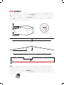
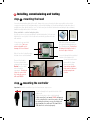
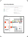
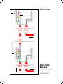
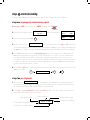
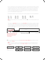
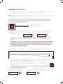
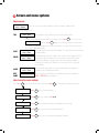
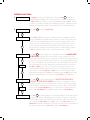
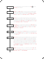
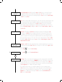
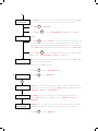
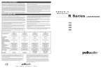
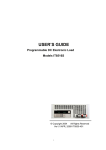
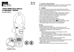
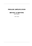
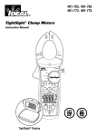
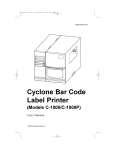
user guide
issue 0025-06
Reflective optical beam smoke detector user guide
1 Distance and position guidelines
These guidelines are recommendations only and it is important that you refer to your
appropriate governing standards at all times.
When positioning your firebeam there are important factors that you should consider, mainly
what distance you are covering and the optimal position in the building.
What distance?
The standard firebeam is suitable for distances of 5m to 40m to the reflector. If you require 40m to 80m you
will need to use the mid range reflector extension kit. For ranges of 80m to 100m you will require the long
range reflector extension kit.
5 to 40 metres the standard firebeam
The standard firebeam comes boxed with the head unit, low level controller, one reflector, 3mm allen key and
quick start installation guide, this should be used for distances over 5m and up to 40m.
Standard firebeam covers 5m and up to 40m
40 to 80 metres - the standard firebeam + mid range 40 to 80m kit
For distances of 40 to 80 metres you will need to use the standard firebeam and
a mid range extension kit (the mid range kit comes with a backing plate and 3
extra reflectors, you will need to add the reflector from the standard kit to the mid
range kit with the screws provided).
80 to 100 metres - the standard firebeam + long range 80 to 100m kit
For distances of 80 to 100 metres you will need to use the standard firebeam
and a long range extension kit (the long range kit comes with a backing
plate and 8 extra reflectors, you will need to add the reflector from the
standard kit to the long range kit with the screws provided).
What position?
A roof is considered flat unless the height of the apex is greater then 0.6m. If the roof is flat thefirebeam system
can be placed anywhere under the roof between 0.3m and 0.6m below the roof, up to a maximum height of
40m from the floor. Thefirebeam has a detection area of 7.5m either side of the beam. If the roof is considered
to have an apex, place thefirebeam system 0.3m to 0.6m down from the top of the apex, up to a maximum
height of 40m from the floor. The maximum protected area either side of the beam can be extended by 1% for
every degree of roof pitch, see the example below:
0.3m - 0.6m
40m max
2.7m min
Field of view should be a 50cm radius from
the centre or the beam
Flat roof
0.3 -0.6m
15m detection area
Extra coverage due to apex angle
100
0.3 -0.6m
15 + (15 x 10%) = 15m + 1.5m = 16.5m
8.25m
8.25m
16.5m detection area
Wall
Wall
Min 0.5m
You should always position the beam at least 0.5m away from any protrusion
Note. Careful design consideration should be made when positioning beams and reflectors in environments
that can be susceptible to condensation i.e. warehouses near to water that have areas open to the outside
environment or that are exposed to quick extreme changes in temperature. To assist with this problem that can
affect all beam detectors we produce an anti-fog kit comprising of a specially coated reflector and lens cover.
Individual reflectors are also available. The standard firebeam and range kits can be supplied as anti-fog sets as
a special order.
2 Installing, commissioning and testing
step 1 mounting the head
Screw the head backing plate to the wall - always try to use as sturdy a location as possible, such as brick
or major structural steels (avoid mounting to outer metal cladding etc). Avoid mounting the head where direct
sunlight can shine directly into the ‘eyes’ of the beam (care should be taken when mounting in glass atriums).
Ambient sunlight will not affect the beam.
Also available - unistrut adapter plate
Use this accessory for easy mounting to unistrut fabrication. Holes are predrilled to the correct pitch of the head and conveniently positioned for use
with unistrut.
Wire into system as required
(see generic wiring diagram on
the following page). Ensure that
all wiring is below the level of
the front edge of the box.
2 knock-outs are provided
on both sides. Take care
when using drills not to
damage the circuit board.
Wire to low level controller using
bottom colour coded terminals.
Screw in through holes provided
outside of the rubber seal.
Screw the head screws
down with the 3mm
allen key provided.
Your wiring should be
flush and not flattened
by tightening down
screws.
Connect the head to
the base plate by first
plugging in the connector.
Do not force in, white
wires should be
uppermost. Should you
forget to connect this
the controller screen
will read ERROR.
step 2 mounting the controller
Important mount the controller at eye level and ensure easy access.
Screw in through holes provided outside of the
rubber seal.
Wire to head using colour coded terminals.
If this connection is not made ERROR will appear
on the controller, this connection can be checked
by reading the resistance across the black and
grey terminals, they will read 110 ohm if OK or
220 ohm if not connected properly.
Generic wiring configurations
thefirebeam is a conventional device, below are suggested wiring configurations for single and multi heads on a
zone. thefirebeam can easily be made addressable with the use of a manufacturers interface and in some cases
can also be powered from the loop, ie with the Apollo XP95 switch monitor with isolator. Most wiring diagrams can
be found on our website in more detail and in PDF format, go to www.thefirebeam.com
Brown
Blue
Black
Grey
Green
+ supply (10.2 - 30Vdc)
- supply (return)
zone +
zone earth (screen)
Supply voltage 12Vdc to 24Vdc + 25% -15%
Quiescent current 3.5mA
Alarm current
3.5mA
Aligning current Normal 3.5mA Fast 17mA
Fault/Alarm relay contact rating 2A @ 30Vdc
FIRE and EOL components as
supplied by the panel manufacturer
Single head on zone
To fire panel
no
c
nc
fault
no
c
nc
fire
FIRE
EOL
manufactured by
technical support
+44 (0)1582 608000
Lemtronics Sdn. Bhd.
Phase 2, Bayan Lepas
Free Industrial Zone
11900 Penang, Malaysia
Fire LED Auxiliary no relay
contact 2A > 30Vdc used
for External LED switching
fire
controller interface
To controller
external
reset
To controller
To fire panel
fault
c
no
fire
c
nc
fire
external
reset
Lemtronics Sdn. Bhd.
Phase 2, Bayan Lepas
Free Industrial Zone
11900 Penang, Malaysia
FIRE manufactured by
nc
Beams 1,2,3...
controller interface
technical support
+44 (0)1582 608000
no
To controller
Schottky barrier diode 1A 60V
MBR160TR (RS 469-0714 or MBR160RGL (farnel 9556761
fault
c
no
fire
c
nc
fire
external
reset
Lemtronics Sdn. Bhd.
Phase 2, Bayan Lepas
Free Industrial Zone
11900 Penang, Malaysia
FIRE manufactured by
nc
...end of line beam
controller interface
technical support
+44 (0)1582 608000
no
EOL
Multiple beams on a zone
Other wiring
diagrams
See our website for further diagrams
including interfacing with
manufacturers protocols
www.thefirebeam.com
step 3 commissioning
Commissioning thefirebeam is a simple procedure outlined in the following step by step explanation.
stage one, language and commissioning speed
1. Important. Do NOT put the reflector up or COVER it if already in place.
thefirebeam PLUS
ver 1.00
2. Power up the unit and you will see
3. Access the menu by pressing enter
Air Quality
0%
Fault
Air Quality
Status
0%
Fire
the screen will default to Status
enter
or
english
if you need to change this use the right and left hand keys to
4. The first screen you see is
scroll through languages, when you have found your language press enter or if you are happy with English press
the down key to continue. If you have changed the language the system will continue in your chosen language.
5. Press enter and you will now see the commissioning speed screen. In most cases it is recommended to use
fast mode (in normal mode the system uses 3.5mA, in fast mode it uses 17mA) - if you are commissioning
more than one beam at a time and the system cannot support the extra draw it may be necessary to use
normal mode to prevent excessive current draw. Fast mode allows x4 times faster motor response and it may
be quicker to commission each beam in turn. Once commissioning is complete thefirebeam will automatically
revert to normal low power mode - (3.5mA).
6. Use the left and right keys to toggle between fast and normal, the
enter key to continue.
left
* indicates which mode is selected. Press the
normal fast*
right
enter
stage two, pre-alignment
pre-alignment
7. The next screen is
this is probably the most important part of setting up your beam.
Pre-alignment sets up the amount of power you need for the distance you are covering and can indicate if you
are receiving unwanted reflections from anything else in the beam path.
8. Press enter to begin pre-alignment. Remember no reflector. You will see the screen below. Take a moment to
understand what the figures on the screen mean.
output signal strength
‘X’ - horizontal lense position in degrees
‘Y’ -vertical lense position in degrees
receiver sensitivity
10.0%
5%
0% P
X+0.000 Y+0.000
received signal strength
‘P’ indicates pre-alignment
R eceiver sensitivity starts off at 5% and output power starts at 10%. The beam will start by raising its sensitivity
first and can rise all the way up to 100%, after this the output power will rise. The objective of pre-alignment is
to adjust the output power to the correct levels for the distance to be covered. As there is no reflector we are
looking for a reflection off the far wall. Power levels will rise until they reach a maximum of anything up to 6
to 7% of received signal strength (nb. figures may fluctuate between these values), once this is achieved the
power level will automatically stop rising any further.
By looking at the table below you need to judge if you are receiving enough power to cover the required distance.
5 m.........5% 10m.......10%
20m.......15%
30m......20%
40m......25%
50m......30%
60m......40%
70m......50%
80m.......60%
90m......65%
100m....75%
Note: Anything more than these levels is good and continue down to 9. If you are receiving noticeably less read
on below.
These figures are approximate but if you are receiving noticeably less than these figures you may be receiving a
reflection from an object nearby and not the far wall. By moving the beam (looking at the far wall) left (x-) right
(x+) up (y+) and down (y-) you can move the beam path away from the obstacle. By doing this you will be able
to achieve a suitable output power. In extreme cases it may be necessary to physically move the beam head to
obtain a clear line of sight.
Obstacle
Reflections from nearby objects will
limit the output power and prevent
ability of the beam to cover the
required distance
Roofline
Sufficient power for distance
Target wall
9. Once you are happy with your power readings press enter to accept pre-alignment and confirm these settings
by pressing the right key.
Note: It may be that no reflection is received and power and sensitivity levels rise to their maximum, if this is
the case pre-alignment will automatically register Pre-Align - Complete. Confirm these settings by pressing
the right key.
10.0% 100% 6% P
X+0.000 Y+0.000
enter
OR If no reflection is seen
you will see this screen.
Press
(right)
to confirm
right
Manual Alignment
enter
Manual
X+0.000
AQ
6%
Y+0.000
Pre-Align - Complete
Press
(right)
right
Manual Alignment
enter
Manual
X+0.000
AQ
6%
Y+0.000
stage three, manual alignment
Y ou will now see the manual alignment screen showing anything between 0 and 6%. This is the amount of
received signal with no reflector that the beam is picking up from the environment.
10. NOW place or uncover the reflector on the blank wall directly opposite the beam head ensuring there is a clear
path through any obstructions such as structural steels etc.
It is important that there is a clear line of sight between the reflector and beam head. The beam must see at
least 200mm of clear space around the reflector to enable the beam to see the edges of the reflector to allow
successful auto alignment in the following stage.
200mm of clear space from the
edges of the reflector
Once the reflector is in place and visible there should be a big jump in the received signal (AQ). This means
that the head is seeing and receiving a signal back from the reflector. In most cases this will result in a
received signal of over 100%. Manual
AQ 136%
Manual
AQ 13%
X+0.000
Y+0.000
3
X+0.000
Y+0.000
7
As long as there is a received signal of over 40% you can move onto the next stage: Auto Alignment,
No.11.
If the AQ reading is below 40% it means the head is not seeing the reflector and will abort Auto Alignment.
The next stage is to manually move the beam to achieve an AQ reading of over 40%, ideally over 100%.
The higher the AQ the quicker it will auto align. This is done by manually moving the x and y motors to
obtain a received signal from the reflector.
In the example below we can see that the reflector is below the eye line of the beam head, so in this case you
would need to lower the angle of the beam (-Y) until you receive an AQ of over 40%.
Beam head
Reflector is lower than the beam head... use -Y to bring the beam onto the reflector
Reflector
The beam can be moved on both X and Y axis to a maximum 5 degrees using the left (x-), right (x+),
up (y+) and down (y-) keys. Looking at the reflector this will move the beam across the reflector like so...
y+
Holding the keys down will quickly scroll through to your desired position, on release of the
button the screen will revert to the actual beam position and can be seen stepping toward
the requested position.
xTo confirm the beam is seeing the reflector covering the reflector at any time should drop the AQ
and prove the beam is on the reflector.
yTry and achieve as high an AQ as possible, it must be over 40% to auto
In the example above moving the y axis
align. The higher the AQ the quicker the auto align, above 100% is good
down (y-) results in a greater AQ
Manual
X+0.000
AQ 6%
Y+0.000
down
Manual
X+0.000
AQ 110%
Y-2.260
down
x+
stage four, auto-alignment
11. Having received an AQ reading of over 40% in manual mode press enter to exit manual and enter again to go
into auto alignment mode.
Auto Alignment
enter
8.7%
67% 103% A
X+0.000
Y+0.000
First you will see the sensitivity and power readings drop if the received signal is over 100%. Once at 100% or
if the reading is under 100% thefirebeam will automatically move its y and x axis until it centres itself onto the
middle of the reflector. It does this by seeing highs and lows as it falls on and off the reflector (seeing the edges
of the reflector) once it has found all the edges it will then calculate and move to the centre of the reflector.
Output signal strength
‘X’ - horizontal lense position in degrees
Receiver sensitivity
12.0%
25% 112% A
X+3.600 Y+4.260
Received signal strength
‘A’ indicates auto-alignment
‘Y’ - vertical lense position in degrees
Auto alignment in ‘fast’ mode will take, on average, 3 minutes and in normal mode up to 30 minutes the
better the beam is aligned before auto alignment (high AQ readings) the shorter the align time. Once finished
Align Complete will appear on the screen, simply press left back to OK and exit.
You will now see this screen AQ may fluctuate a couple of % above and below 100%
Air Quality 100%
Status - NORMAL
Now proceed to step 4 - testing - the final stage of commissioning.
step 4 testing
1. Fault test This is done to confirm that the returned signal is from the reflector. Cover the
entire reflector within one second. If the beam is correctly targeted onto the reflector the AQ
will drop to 0% (max 10%) and will fall into a ‘fault’ condition (after 10 seconds). Amber LEDs
will flash on both the controller and the beam head, the word FAULT will appear on the display.
If the AQ is still above 10% reflections are also being returned from something else other than
the reflector. This should be rectified and a fault test performed again until AQ drops below 10%.
2. Fire test Having completed the fault test the fire test confirms the functionality of the beam.
Having just covered the reflector completely for the fault test now let the beam recover to its
normal state and then cover half the reflector, in effect restricting the returned signal to 50%,
the beam should then fall into a ‘fire’ condition (after 10 seconds).
Once you have successfully completed both tests your firebeam is commissioned.
You can now fine tune your beam to suit the environment if needed. Look through the following menus
to see adjustments that can be made.
3 Screen and menu systems
Home screen
Air Quality 100%
Status – NORMAL
This is the screen you would normally see when the beam is commissioned.
Other screens you may see are:
Air Quality 29%
Status – FIRE
FIRE
The air quality level has fallen below the fire threshold setting.
If alarm is set to latching and you need to reset from fire press enter
enter
to see this screen:
Alarm Reset
and press enter enter again to reset and return to the normal screen.
This can also be reset by dropping the power to the beam for 5 seconds. If set to auto reset it
will reset to normal automatically.
FAULT
Air Quality 0%
Status – FAULT
The beam path has been fully blocked within 1 second (used when fault testing
commissioning.
in
ERROR
Air Quality XX
Status – ERROR
No communication with the controller. This could be that the flying lead is not
connected,
or that the head is not connected to the controller, this can be
checked by reading the resistance across the black and grey terminals,
if connected it should read 110ohms if not connected at one end this will
read 220ohms.
ALIGN
Air Quality 89%
Status – ALIGN
This screen will appear when the beam is performing a self alignment,
normally
because of building movement.
DIRT
COMP
Status – Dirt Comp
This is due to the compensation for dirt build up reaching its maximum FAULT
or FIRE LED may be flashing.
How to use the menu system
Press enter
enter
to go into the menu system, then press down
English
Commission
Mode Change
Beam Maintenance
Diagnostics
down
to go through the main menu options:
enter
enter
here to change languages.
enter
enter
here to commission firebeam.
enter
enter
here to make all changes and adjustments to the beam.
enter
enter
here as part of your routine maintenance.
enter
enter
here to access power and temperature headings.
Individual menu items
1.
Language
2.
Commissioning
The language is factory set to English if this is okay press enter enter to continue to
commissioning
or arrow up to return to the home screen. To change the language use
the right and left keys to change to your preferred language and press enter to confirm
your choice – you will then continue in the language of your choice. Languages currently
available are: English, Dutch, Italian, French, Spanish, Czechoslovakian and German.
Press enter
enter
to go into commissioning.
enter
Normal
Fast*
enter
Pre-Alignment
enter
X
Y
enter
Manual Alignment
enter
X
Y
Pressing right or left changes between normal and fast. It is recommended in most
cases
to use fast mode (in normal mode the system uses 3.5mA, in fast mode it uses
17mA) - if you are commissioning more than one beam at a time and the system
cannot support the extra draw it may be necessary to use normal mode to prevent
excessive current draw. Fast mode allows x4 times faster motor response and it
may be quicker to commission each beam in turn. Once commissioning is complete
thefirebeam will automatically revert to normal low power mode - (3.5mA).
Press enter enter to start pre-alignment. In pre-alignment you should always cover
the
reflector. Starting at 10% power and 10% receiver sensitivity, the receiver
sensitivity will automatically increase to a maximum of 100% then the output power will
increase. These settings will automatically stop when a received signal strength reaches
6% - this received signal is the returned strength of the output signal without a reflector
(if no return signal is received the beam will reach full power and the screen will say
Pre-Align - complete). If you don’t receive high enough output power and receiver
sensitivity readings this will usually be because you are receiving a reflection from an
object nearby - use the left, right, up and down keys to avoid the obstruction. When
happy with your readings press enter and confirm by pressing the right button, this will
take you to manual alignment - if you wish to abort Pre-Align press the left button.
Press enter enter to go into manual alignment - now the reflector can be
placed
or the cover can be removed. You should see a large jump in signal
strength. If no jump is seen use the X and Y keys to locate the reflector (the better the
single strength the better the beam is aligned) try to achieve a figure of around 100%
or over for optimum auto alignment times - you must achieve a signal strength over
40% to start auto alignment. Press enter to okay this and go to auto alignment.
enter
Auto Alignment
Press enter enter to start auto-alignment. The beam will calibrate its power and search for
the
edges of the reflector – adjusting its power as it aligns itself onto the reflector. Once
it has found all four edges twice it will then centre itself on the middle of the reflector and
the screen will say align complete. Press enter to return to the home screen. If you see
align aborted this means something has crossed the beam path of the received signal and
the signal has dropped out. Press back / left to return to auto alignment.
3.
Mode Change
Here we can make changes to how the beam behaves. Press enter
mode change and the sub menus.
enter
to go into
enter
Threshold
Threshold. Use the right and left keys to increase or decrease the beams sensitivity.
It is factory set at 35% (meaning the received signal has to drop by 35% to trigger
the fire relay. This sensitivity can be adjusted between 25% (sensitive) and 50% (less
sensitive) (press enter to return to mode change or down to go to time to fire).
Time to fire
Time to fire. Here we can adjust how long the beam has to be in fire before the fire
relay
is triggered. This is factory set at 10s, you may want to increase this if there is
something that may momentarily obscure the beam path (birds / forklift truck) this can
be adjusted between 2 and 30 seconds by using the right and left keys (press enter to
return to mode change or down to go to time to fault).
Time to fault
Time to fault. Here we can adjust the time to fault between 2 and 60 seconds (factory
at 10 seconds). For a beam to go into fault the beam path must be totally blocked
set
within ONE second. By using the right and left keys (press enter to return to mode
change or down to go to auto reset).
Auto reset
Auto reset. The beam is factory set to auto reset when the received signal raises above
fire threshold hysteresis. This can be set to latching if your system requires this.
the
Change by using the right and left keys (press enter to return to mode change or down
to go to align on / off).
Align On/Off
Align on / off. You may want to turn the auto alignment function off, for example, in an
environment
that often gets filled with welding smoke, the auto align function kicks
in when the received signal drops below 90%, the point that the beam automatically
checks for building movement. The beam will try to align through the smoke which
could be a problem if it is unable to see the edges of the reflector. Use the right and
left keys to turn off and on. When turning this function off extra care should be taken
to ensure that the beam head is on a sturdy fixing ie., brick wall or major structural
steel. Auto alignment will still function in commissioning (press enter to return to mode
change or down to go to align time).
Align Time
Align time. This is factory set to 4hrs, you can adjust this, by using the right and left
keys,
between 0 to 12 hours depending on your environment (press enter to return to
mode change or down to go to green flashing light).
4.
Green Flashing Light
On / Off
Green flashing light on / off. By using the right and left keys you can turn the green
flashing
LED, located on the head and controller, on or off. This is a useful way of
identifying the beam head you are working with (press enter to return to mode change
or down to go to phase).
Phase
Phase. When using multiple beams that face each other the beam output signals could
phase
together and can cause unreliable readings, by setting each beam to phase
differently alleviates this problem. Use the right and left keys to give each beam a
different phase pattern (length between output beam sample times) you can choose
between 0 (default setting) and 6 (press enter to return to mode change or down to go
to hysteresis).
Hysteresis
Hysteresis. Changing the hysteresis will change the delay in returning from a fire
state
back to a normal state, for example, the beam is factory set at 15% so if the
beam falls into fire at 65% (35% threshold) it has to recover 15% to 80% before it
returns to normal. This action prevents small fluctuations in returned signal causing
the beam to fall in and out of a fire state. This can be adjusted between 1% and 40%
by using the right and left keys (press enter to return to mode change or down to go to
compensation fire / fault).
Comp
Fire – Fault
Comp fire – fault. When dirt compensation has reached its maximum you can choose
whether
the beam signals fault or fire, this is factory set to fault, use the right and left
keys to change this.
Beam Maintenance
Press enter
enter
to return to mode change.
Press enter
enter
to go into beam maintenance.
enter
Dirt Comp
Dirt Comp. This screen shows how much the beam has compensated for dust build on the beam head and reflectors, ALWAYS take a note of this value as part of your
up
routine maintenance to see any build-up pattern, if you see figures above +50% you
should clean both the lens face and the reflectors (once cleaned you should instigate
an auto alignment to re-calibrate the beams settings).
It is possible that you may see a negative number here, this can happen when
thefirebeam has been commissioned in a ‘dirty’ atmosphere such as builders dust
which, once cleared, the beam then compensates for. To reset, perform an auto
alignment to re-calibrate the beam (press enter to return to beam maintenance or
down to go to event counts).
Alarm & Fault
Event Counts
Event counts. Here we can see how many times the beam has gone into fire or fault
since
the beam was commissioned or since the event log was last cleared.
Press enter
enter
Press left / back
Self Test
to clear events.
left/
back
to return to beam maintenance or down to go to self test.
Self test.
Press enter enter to perform a fire test, this works by running a test algorithm to lower
the output power, the receiver sees this as obscuration. When the received signal
drops below the threshold point the beam will trip the fire relay – this relay will not trip
until the time to fire has passed which could be anything between 2 and 30 seconds.
left/
Press left / back back to end test, the fire test should show on the panel. Press left /
back to return to beam maintenance or down to go to on / off.
On / Off
On / off. If something needs to be maintained in the beam path use the right and left
keys
to turn the system on and off.
This will show as a fault on the panel.
5.
Diagnostics
Press enter
enter
to return to beam maintenance.
Press enter
enter
to go into diagnostics.
enter
IR Power
RX Sensitivity
Temperature
Temp Comp xx%
IR power. This screen shows the amount of output power that is being transmitted.
It can be increased or decreased by using the right and left keys (press enter to return
to diagnostics or down to go to RX sensitivity).
RX sensitivity. This screen shows the receiver sensitivity and can be changed by
using
the right and left keys (press enter to return to diagnostics or down to go to
temperature).
Temperature. Here we can see the temperature at the beam head and the amount of
compensation
being made for temperature (no adjustments can be made here).
Press enter
enter
to return to diagnostics.
technical specifications
Electrical Specifications:
Supply Voltage. 10.2 to 30 VDC
Supply Current. 3.5mA (constant current)
in all operational states
Constant Current. 17mA (constant current)
in fast commissioning
Environmental Specifications:
Temperature. -10°C to +55°C
Humidity. 10 to 95% RH Non-condensing
Protection Index. IP65 when suitably
mounted and terminated
Mechanical Specifications:
Beam Head.
180mmH x 155mmW x137mmD
Weight 1.1Kg
Controller.
185mmH x 120mmW x 62mmD
Weight 0.55g
40KIT80 Mid-Range Reflector.
293mmH x293mmW x 5mmD
Weight 0.8Kg
80KIT100 Long Range Reflector.
394mmH x 394mmW x 5mmD
Weight 1.8Kg
Adapter.
270mmH x 250mmW x 5mmD
Weight 0.6g
(mounts the Beam Head onto unistrut)
Optical Specifications:
Optical Wavelength. 870nm
Maximum Angular Alignment. ±5°
Maximum Angular Misalignment.
(static not auto-aligning)
Beam Head ±0.75° Reflector ±2°
Operational Specifications:
Protection Range:
FIREBEAM.
Standard Product 5 to 40 metres
40KIT80.
Mid-Range Reflector Kit 40 to 80 metres
80KIT100.
Long Range Reflector Kit 80 to 100 metres
Alarm Sensitivity Levels:
25%(1.25dB) to 50%(3dB) in 1%(0.05dB)
increments (default 35% (1.87dB))
Alarm Condition:
Obscuration drops to below pre-defined
sensitivity level.
Time to Alarm Condition adjustable
2 to 30 seconds in 1 second increments
(default 10 seconds)
Alarm Indication:
Controller Status – FIRE
Controller Red Flashing LED
Head Red Flashing LED
Alarm Relay Change Over (CO) Contact
Rating 2A @ 30 VDC
Test/Reset Features:
Beam test function by controller
Alarm latching/auto-reset selectable
(default auto-reset)
Alarm reset in latching mode by controller
reset function, removing power for >5
seconds, apply 12 to 24 VDC to reset
connections in Beam Head.
Fault Sensitivity Level:
90%
Fault Condition:
Obscuration drops to below the fault
sensitivity level within 1 second
Power Down or Supply Voltage < 9 VDC
Commissioning modes, Pre-Alignment
and Auto Alignment
Beam turned off during Beam Maintenance
Time to Fault Condition adjustable,
2 to 60 seconds in 1 second increments
(default 10 seconds)
Fault Indication:
Controller Status – FAULT
Controller Yellow Flashing LED 1 Second
Head Yellow Flashing LED 1 Second
Fault Relay Change Over (CO) Contact
Rating 2A @ 30 VDC
Normal Condition:
Obscuration level is above the
Alarm sensitivity level
Controller Status – NORMAL
Controller Green Flashing LED
Programmable on/off
Head Green Flashing LED
Programmable on/off
Auto-align/Beam Contamination
Compensation:
Auto-align during normal operation if
obscuration drops below 90% for the
duration of the align time set
(doesn’t effect normal operating mode)
Beam Contamination Compensation 4 hour
monitoring. Compensation data available at
the controller