1
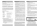
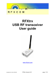
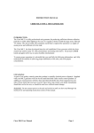
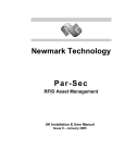
To change the ‘Set Point’ (i.e. the temperature requested)
press and hold the ‘SET’ button and at the same time press
‘+’ or ‘-’ to increase or decrease the temperature setting.
The display will continue to show the ‘Set Point’ until the
‘SET’ button is released. The display will then show actual
temperature.
USER GUIDE
TLX 7506
RF Digital Room Thermostat
The TLX 7506 is a Radio Controlled Room Thermostat which
requires no wiring and can be fitted in any normal operating
environment within a typical 30 metre range of the TLX 1206
RF Receiver.
The TLX 7506’s unique security code is installed into the RF
Receiver as part of the commissioning procedure ensuring
that your RF Receiver will only respond to instructions sent
to it from your TLX 7506 Transmitter. How this is done is
detailed in the Commissioning Instructions later in this guide.
TLX 7506 Technical Data
Temperature Range:
5 oC to 35 oC in 1oC steps
16 oC to 35 oC selectable
o
When the TLX 7506 instructs your heating system to
switch on a small flame symbol appears at the bottom right
of the display. This symbol will be displayed only when
the thermostat is calling for the heating system to be on.
The ideal position to locate the TLX 7506 Digital Room
Thermostat is about 1.5m above floor level, accessible,
reasonably lit and free from extremes of temperature and
draughts.
Do not mount on an outside wall, above a
radiator or where it may be subjected to direct sunlight.
The wireless nature of the installation means that the
thermostat can now be positioned in any room to provide
optimum thermal response rather than to minimise or
simplify the installation wiring.
It is recommended the commissioning procedure be
carried out before fixing the mounting plate to ensure the
chosen locations are suitable for transmitting and receiving
radio signals.
Differential:
<1 C at 4 C per Hour
Installation:
Ambient Temperature:
Operating 0 oC to 45 oC
Please read all instalation instructions before proceeding.
Power Supply:
Two type AA 1.5V alkaline cells
(supplied)
Battery Life:
2 years typical
Wiring:
No wiring required
Maintenance:
No user maintenance required
Radio signal range:
30 metres typical
Conforms to:
DTI MPT1340 (licence exempt)
Operation:
The TLX7506 Digital Room thermostat is simple to use.
The large 12mm Liquid Crystal Display continuously shows
actual room temperature.
To display the temperature requested (the Set Point) press
and hold the button marked ‘SET’.
On releasing this
button the display will revert back to actual temperature.
The unit is supplied with a 5 oC minimum temperature set
point and configured as a heating thermostat as factory
defaults. Two internal links can be used to re-configure
these defaults.
1.
2.
Position:
o
Year 2000 compliant in accordance with BSI PD2001
Configuring:
The TLX 7506 Digital Room Thermostat is battery powered
and operated by radio control. It does not require any
electrical connections.
If it is replacing an existing hard
wired thermostat, isolate and make safe the wiring to the
old thermostat as it is no longer required.
All electrical wiring changes must be carried out by a
competent person in accordance with the latest appropriate
Wiring Regulations.
Be sure to switch off the mains
supply before removing any existing thermostat.
3.
4.
Battery Replacement:
This is the only maintenance required for this product.
A ‘flashing’ battery low symbol will appear at the bottom
left of the display when the batteries start to approach the
end of their life. This indicates that they should be replaced
within the next month. Normal operation will be maintained
during this period. Ultimately the complete display will start
flashing at which time the thermostat will switch off the
heating and shut down until the batteries are replaced.
To replace the batteries the following procedure should be
carried out.
1.
2.
Fixing:
1.
2.
3.
The metal mounting plate supplied should be
positioned with a minimum of 70mm clearance to left,
right, above and below to allow adequate airflow.
Fix the mounting plate directly to a flat wall using the
wall plugs and screws provided.
Remove the battery insulation strip protruding from the
rear of the unit. Check the unit is functioning and fit to
the metal mounting plate on the wall.
Open the unit by slackening the retaining screw on the
lower side and hinge unit upward along the top edge
to separate it from the plastic base. Remove the
batteries.
Locate and identify the two option Links 1 and 2. Use
a pair of small wire cutters to carefully cut the
appropriate links to give the required configuration.
Cutting Link 1 will give a minimum temperature set
point of 16 oC (factory default is 5 oC). Cut Link 2 to
display cooling symbol instead of heating symbol.
Please ensure the RF Receiver (TLX 1206) is wired
for a cooling application (i.e. using contacts 2 and 4).
Carefully replace batteries being sure to observe the
correct polarities.
Re-fit plastic base and tighten
retaining screw. Check unit is functioning as required
and fit to metal mounting plate on the wall.
3.
Remove the unit from the wall-plate by sliding
upwards and gently pulling away from the wall.
Slacken the retaining screw on the unit and open by
hinging upwards along the top edge.
Carefully remove batteries from the battery
compartment and fit two new
'AA' alkaline cells
taking care to observe the correct battery polarities.
Check unit is functioning and re-fit to the plastic base
by hinging downwards from the top edge. Ensure unit
is properly closed and re-tighten the retaining screw.
Re-mount onto the metal wall-plate and check the TLX
7506 is still in radio communication with the RF
Receiver. This is easily done by adjusting the set
point to switch on and off the heating system several
times and checking the green indicator on the RF
Receiver goes on and off accordingly.
TLX7506_User 16/8/99(Rev.) P.1
Commissioning:
Checking the RF circuit:
This is the process of establishing communication
between the Sunvic TLX7506 (RF Transmitter) and the
TLX1206 (RF Receiver).
1.
The following assumes that the TLX7506 Room Thermostat
and the TLX1206 RF Receiver have been installed in
accordance with the appropriate instructions.
The commissioning procedure is simple and straightforward,
however should difficulties be experienced see the ‘Hints
and Tips' section below.
It is important to read through
these instructions once before carrying out the proceeding.
The procedure consists of putting the TLX 7506 Thermostat
in a mode where it repeatedly sends a unique security install
code. During this time the RF Receiver is put into install
mode when it receives and holds this unique security code.
The receiver will then respond to signals from that particular
TLX 7506 Thermostat.
2.
3.
4.
RF Receiver LED’s (indicators):
Red LED
‘flashing’
Red LED
‘steady on’
Red LED
‘slowly pulsing’
5.
- Indicates receiving an RF signal.
- Indicates a fault condition.
e.g. RF signal not being received.
- Indicates a valid Install code
has been received.
Green LED
‘steady on’
- Indicates demand for heat.
Green LED
‘Off’
- No demand for heat
i.e. Heating call satisfied.
Checking the hard wired circuit:
1.
2.
Apply power to the TLX1206 RF Receiver. Ensure
any separate programmer in the heating circuit is
calling for heat. The red LED should be off.
Press the TEST button. The Green LED should come
on. Check that the boiler and/or motorised valve have
been operated.
Remember to allow adequate time
for the valve to open. Press Test button again. The
Green LED should go out closing any valve and
switching off the boiler.
Note:
6.
Test Mode will automatically switch off after
15 minutes.
7.
Press and hold the + and - buttons on the TLX 7506 for
at least 3 seconds. The TLX 7506 will then transmit its
unique digital security code every 10 seconds for the
next 5 minutes. The display will show flashing ‘ ] ] ] ‘
while this is happening
Within the 5 minute period go to the TLX 1206 RF
Receiver. Press and hold the Install button and then
press the TEST button while the INSTALL button is
held. This will clear out any previously installed codes.
The Red LED will pulse slowly for 3 seconds to indicate
this has been done.
Next, place the Receiver in Install mode by pressing
and holding the INSTALL button (for at least 10
seconds). The Red LED will come on and stay on until a
valid Install Code has been received. When this
happens the Red LED will start pulsing slowly and the
install button can then be released. The Red LED will
pulse for a further 3 seconds and then go off. The Install
code has been successfully received.
Go to the Thermostat Transmitter and press any key to
stop the transmission.
The display will stop flashing
‘ ] ] ] ‘ and return to normal.
The TLX 1206 RF Receiver will now only respond to
radio signals with the installed code i.e. from the TLX
7506 Thermostat just installed. Even if the power is
removed from the Receiver it will not forget the installed
code.
Check that the TLX 7506 and the TLX 1206 are
communicating with each other by adjusting the
TLX7506 Thermostat set point above or below the
actual temperature thus generating a radio signal
requesting the heating to come on or off and check that
the boiler responds as expected. The Red LED on the
receiver will flash for 3 seconds each time a radio signal
is received. This will happen every time the TLX 7506
Thermostat calls for the heating to be switched on or
off.
The TLX 7506 Thermostat also sends a radio signal
every 5 minutes to make sure that the TLX 1206
Receiver knows what state it should be in. Therefore
every 5 minutes the Red LED will flash for 3 seconds.
If the TLX 1206 does not receive regular RF signals the
Red LED will come on indicating that a fault condition
has occurred and the heating system will be switched
off.
Note: If more than one Radio Controlled Digital Room
Thermostat System is fitted within the same property it
is important that the above procedure is used to install
each Room Thermostat in turn so they are
correctlmatched to the relevant Receivers.
Hints and Tips:
1.
Receiver RED LED ‘steady on’
This could be an indication of dead batteries or some
temporary interference with the radio signal.
2.
Commissioning
If nothing has happened after 20 seconds of holding
the Install button pressed check the TLX 7506
Thermostat is still transmitting (i.e. it may have been
more than 5 minutes since it was started).
3.
Minimum Set Point
If while adjusting the set point it is found that it cannot
be set below 16 C check that the with the installer that
the unit has not been configured to restrict the
minimum set point (this is often required for
installations in sheltered accommodation). See
‘Configuring’ above for details of how to re-configure
the unit.
4.
Failure to operate:
If the heating fails to come on when the thermostat is
calling for heat check the battery low indicator on the
thermostat display. If the display has faded replace
the batteries as you may have previously overlooked
the battery low indications. If the batteries are
removed for more than 5 to 10 minutes the unit may
need to be re-commissioned (see above).
5.
If there are any problems when fitting batteries i.e.
blank or partial display, reset the unit by REMOVING
the batteries and holding any key pressed for 10
secs. to fully discharge any residual voltage.
This product complies with the essential requirements
of the following EC Directives:
Electro-Magnetic Compatibility directive
EMC 89/336/EEC (as amended by 91/263/EEC
and 92/31/EEC)
Low Voltage Directive.
LVD 73/23/EEC; 93/68/EEC
SUNVIC CONTROLS LTD.
Bellshill Road, Uddingston, Glasgow G71 6NP
Tel: (01698) 812 944 Fax: (01698) 813637
Technical Helpline Tel: (01698) 810945
In the interests of continuous product improvement Sunvic
Controls reserve the right to alter designs, specifications and
materials without prior notice and cannot accept liability for error
TLX7506_User 16/8/99(Rev.) P.2