1
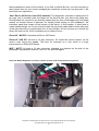
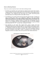
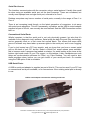
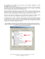
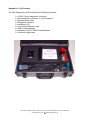
5AS SECURITY CONTROLLER DIAGNOSTICS
USER’S GUIDE
RELEASE VERSION 1.05
Information contained within this document may not be reproduced without prior permission.
Copyright 2004 Avon Automotive Diagnostics Ltd
1
Contents
CONTENTS ....................................................................................................................................................... 2
VEHICLE APPLICATIONS .................................................................................................................................... 3
FEATURES ....................................................................................................................................................... 3
Remote Control Matching........................................................................................................................... 3
Immobiliser Over-Ride Code Retrieval....................................................................................................... 3
Live Input Monitoring .................................................................................................................................. 3
Programming and Coding Options ............................................................................................................. 3
PC REQUIREMENTS ......................................................................................................................................... 4
INSTALLING THE SOFTWARE .............................................................................................................................. 5
PLUGGING IN AND DIAGNOSTIC CONNECTOR LOCATIONS ................................................................................... 6
RUNNING THE SOFTWARE............................................................................................................................... 10
Password Entry Screen............................................................................................................................ 10
Select a Serial Port Screen ...................................................................................................................... 10
Main Diagnostic Selection Page............................................................................................................... 11
Match Remote Controls Screen ............................................................................................................... 11
Instructions on matching: ......................................................................................................................... 12
Read Immobiliser Over-Ride PIN ............................................................................................................. 12
Monitor Inputs........................................................................................................................................... 13
Programming Options .............................................................................................................................. 14
Programming Options > Clear Factory Mode........................................................................................... 14
Programming Options > Turn OFF Passive Immobiliser ......................................................................... 15
Programming Options > Turn ON Passive Immobiliser ........................................................................... 15
Programming Options > Reprogram Bonnet Switch Input ....................................................................... 16
Programming Options > Read / Write Code Sent To The ECM............................................................... 16
Test Communications With Car................................................................................................................ 17
Test Horn Circuit....................................................................................................................................... 17
Interface Status ........................................................................................................................................ 18
ABOUT THE INTERFACE .................................................................................................................................. 19
TESTING THE INTERFACE ON THE BENCH ........................................................................................................ 19
OUR POLICY ON SOFTWARE BACK UPS / MULTIPLE INSTALLATIONS .................................................................. 20
NOTES ON MATCHING REMOTES ..................................................................................................................... 21
SERIAL PORT ISSUES...................................................................................................................................... 22
Conventional Serial Ports:........................................................................................................................ 22
USB Serial Ports:...................................................................................................................................... 22
APPENDIX 1: KIT CONTENTS ........................................................................................................................... 24
APPENDIX B: 5AS PIN OUTS .......................................................................................................................... 25
APPENDIX C: CONNECTOR VIEWS............................................................................................................. 26
Please note: Throughout this document, there are a number of ‘screen shots’ showing what the software for
this diagnostic tool looks like under various circumstances. These are real screen shots taken from real
laptop computers communicating with cars.
Because of the way Microsoft Windows works, the actual appearance of this software running on other PCs
may differ slightly from that shown, for example Windows may use a different font for certain texts. This is
entirely normal.
All information contained within this document is given in good faith, but Avon Automotive Diagnostics Ltd
will not be held liable for any inaccuracies or omissions.
Also, due to a policy of continuous improvement, customers may be supplied with a version of software, and
product, that is later than that shown.
All Trademarks are acknowledged.
This document is the intellectual property of Avon Automotive Diagnostics Ltd. Unauthorised copying or
redistribution of this document, or any part of it, is strictly prohibited.
Information contained within this document may not be reproduced without prior permission.
Copyright 2004 Avon Automotive Diagnostics Ltd
2
Vehicle Applications
The TRW (formerly Lucas) 5AS security controller can be found on the following MG
Rover vehicles:
•
•
•
•
•
•
•
•
•
•
Rover 200/400 Series, including Coupe, Tourer and Cabriolet. 1994.5 Model Year
onwards.
'New' Rover 200 Series, Launch (1995 Model Year) onwards
'New' Rover 400 Series, Launch (1995 Model Year) onwards.
Rover 100 Series, from launch (1995 Model Year) onwards.
Rover Mini, 1995 Model Year onwards.
MGF, from launch (1996 Model Year) onwards.
Rover 25 Series, from launch (2000 Model Year) to 2004 Model Year.
Rover 45 Series, from launch (2000 Model Year) to present.
MGTF, from launch to 2004 Model Year
Also a number of low volume cars which use K Series engines, including Lotus Elise,
GTM Libra etc.
Note that a diagnostic socket adapter will be required to connect to earlier (usually pre1996) vehicles. This is supplied as part of the kit. See the ‘Plugging In’ section later on in
this document.
Features
The Avon Diagnostics 5AS Diagnostic Kit gives the user the following features:
Remote Control Matching
The Diagnostic Kit can be used to put the 5AS Unit into remote control ‘Learn Mode’. This
allows up to a maximum of 4 remote control handsets to be matched to a 5AS Unit at any
one time.
Immobiliser Over-Ride Code Retrieval
This allows the user to read the 4 digit immobiliser over-ride code, often referred to in
Rover literature as the EKA (Emergency Key Access) code. This 4 digit code can be used
to disarm the immobiliser, should the remote control handset fail for any reason.
Live Input Monitoring
This allows the user to watch, in real time, the status of the many switches which form
inputs into the 5AS. This allows problems such as false alarms and locking failures to be
rectified quickly.
Programming and Coding Options
These features can be used when a replacement 5AS unit (new or used) is fitted to a
vehicle, so that the replacement functions correctly. The features include the ability to read
the immobiliser code from the original 5AS, and program this into the replacement, so that
the engine management unit doesn’t require recoding. A number of other tasks are also
available, which allow the user to alter the functionality of the 5AS.
Information contained within this document may not be reproduced without prior permission.
Copyright 2004 Avon Automotive Diagnostics Ltd
3
PC Requirements
The specification of PC required to run this diagnostic tool is very modest. From the outset
the tool has been designed to work on a large range of PCs, from fairly elderly machines,
right up to the latest 3GHz + machines, which are usually supplied without serial ports.
The minimum specification is as follows:
Processor type: 486 33MHz or better
Operating System: Microsoft Windows 95, 98, ME, NT, 2000 or XP. Windows 98 or better
is required for USB connectivity.
Hard Drive Space Requirement: 10Mb (maximum)
RAM: 32Mb recommended.
Connectivity Requirements: 1 spare 9 RS232 way serial port, OR an available USB
connection. USB 1.0 or later can be used, and the connection can be run through a hub if
necessary.
If a USB connection is to be used, a USB to serial adapter is supplied as part of the kit, to
allow the interface to be connected. It is recommended that the adapter supplied is used,
rather than any other type, because the specification and performance of these devices
vary widely.
View of the rear of a typical laptop, showing the 9 way ‘D-type’ connector for the serial port
Similar view of the back of a laptop, this time showing a single USB port. Note the standard USB logo
(lower arrow).
Information contained within this document may not be reproduced without prior permission.
Copyright 2004 Avon Automotive Diagnostics Ltd
4
Installing the Software
The setup program needed to install the diagnostic software should automatically run as
soon as the installation CD is placed into your CD drive.
If however, the set up fails to run, then this is probably because the ‘Auto-Run’ feature is
turned off for that particular CD drive in your Windows Control Panel. If this happens, using
Windows Explorer, go to the folder ‘Setup’ on your CD drive (usually called D:\Setup) and
double click on the file called Setup.exe.
You are advised to do this with the minimum of other applications running.
Once the setup is running correctly, you should see the following screen:
From there onwards, follow the on-screen instructions.
Once the program has been successfully installed, it can be launched by clicking on the
Start Button, and then choosing ‘Programs’, then ‘Avon Diagnostics’, then ‘5AS
Diagnostic’.
Information contained within this document may not be reproduced without prior permission.
Copyright 2004 Avon Automotive Diagnostics Ltd
5
Plugging In and Diagnostic Connector Locations
All vehicles fitted with the 5AS system have a diagnostic connector. There are two types of
connector used: earlier cars (generally pre-1996) use a 3 pin round, green diagnostic
connector, and this is always in the engine compartment, under the bonnet. Later models
have a standard 16 pin J1962 or OBD socket, and this is always in the passenger
compartment.
The green 3 pin diagnostic connector is protected from dirt ingress by a rubber cap. It
doesn’t contain the live (12V) supply needed to power the Diagnostic Interface. The
adapter supplied as part of this kit comes with a red crocodile clip so that the Interface can
be powered from a convenient 12V source, which is usually the battery + terminal post.
Note: On cars fitted with the green 3 pin diagnostic connector, there’s usually a
white 3 pin connector in close proximity. This is the diagnostic connector for the
MEMS engine management unit (see photo on next page). These two connectors are
physically identical, (apart from the colour) and so it is possible to accidentally
connect the adapter in this kit to the white socket. If this happens and you attempt
to communicate with the 5AS, whilst connected to the MEMS, no damage will be
done to either the MEMS unit or to the Interface. Obviously though, the diagnostic
won’t work in this case.
At times, finding the diagnostic socket is actually the hardest part of using this diagnostic
kit.
The list below should provide some guidance as to the diagnostic connector type and
location:
Mini:
Pre 1996 Models, with single point injection use the round 3 pin connector, located
under bonnet, normally in the top right hand corner of the engine bay, just below the
bonnet hinge.
Post 1996 models with twin point injection (and usually airbags) have a 16 pin
diagnostic socket, very near the steering column hanger bracket.
Rover 100:
Pre 1997 models (that’s almost all of them) have the round 3 pin socket, located under
bonnet, in the top right hand corner.
Post 1997 models have a 16 pin socket under the driver’s side of the fascia.
Rover 200/400 Series, Including Cabriolet, Coupe (often referred to as Tomcat), and
Tourer use the round 3 pin connector, located under bonnet, normally next to the engine
bay fuse box.
Rover 200/400 Series, after 1996, consisted only of the Cabriolet, Coupe and Tourer.
These models had the fascia from the Post 1995 Rover 200, and so had an in-cabin 16
way connector, which shared the same problems as this car (see below).
‘New’ Rover 200 Series, from 1995 onwards: This model always had an in-cabin 16 way
diagnostic socket. The connector is on the driver’s side of the transmission tunnel, and is
clipped onto a metal bracket. It is SUPPOSED to face towards the pedals. But
unfortunately, a number have been clipped in so that the mating face of the connector
Information contained within this document may not be reproduced without prior permission.
Copyright 2004 Avon Automotive Diagnostics Ltd
6
faces towards the centre of the vehicle. If you find a vehicle like this, you will now have to
spend some time on your knees unclipping the connector so that you can plug into it. We
know this from experience…
‘New’ Rover 400 Series, from 1995 onwards: The diagnostic connector is always the 16
pin type, and is located under the fascia on the driver’s side, just above the pedal box.
Unfortunately the connector isn’t actually clipped into any form of stowage point, and floats
around on several inches of harness. It’s usually found resting on the cardboard / felt
insulation panel that closes off the bottom of the fascia. In this location, it does tend to
create rattles though, so it’s not unusual to find the connector cable-tied to some other part
of the main harness, or pushed down the ‘A’ post finisher. We’ve not been to a vehicle yet
where it’s been cut off, but it’s probably only a matter of time…..
Rover 25 / MG ZR: Comments as Rover 200 Series.
Rover 45 / MG ZS: All have a 16 way connector. It’s inside the centre console, on the
driver’s side, facing the pedals. This time it’s mounted on a clip, which is a huge
improvement on Rover 400 Series
MGF / MGTF: All have a 16 way connector, attached to a bracket on the side of the
passenger compartment fuse box. Yes it is. Go and look again!
Rover 45 / MGZS Diagnostic connector, shown arrowed, with clutch pedal in foreground
Information contained within this document may not be reproduced without prior permission.
Copyright 2004 Avon Automotive Diagnostics Ltd
7
Under bonnet view of a 1994 Rover 214 SEi hatchback, showing the 3 pin round diagnostic socket.
Don’t confuse it with the white / clear one, and remember to replace the waterproof cover after use.
The same car, this time with the 3 pin to 16 pin adapter in position.
Information contained within this document may not be reproduced without prior permission.
Copyright 2004 Avon Automotive Diagnostics Ltd
8
Rover 400 diagnostic connector, from a 1998 car, shown with the oddments stowage bin removed.
As this connector isn’t actually clipped into a bracket, its not unusual to find it taped to something to
stop it rattling.
Information contained within this document may not be reproduced without prior permission.
Copyright 2004 Avon Automotive Diagnostics Ltd
9
Running The Software
This section should take you through the actual functions of the software, and give you a
description of what each does.
Password Entry Screen
This is the first screen that you’ll see on
launching
the
5AS
Diagnostics
application. It’s obviously there as a
security precaution, to ensure that this
software can’t be used by unauthorised
persons. Use the password that was
given to you when the diagnostic kit was
supplied. The password can’t be
changed. Note that for the sake of
security, it’s recommended that you don’t
write the password down, or leave it with
you computer gear.
Select a Serial Port Screen
This is the next screen that you’ll see after
correctly entering a password. The screen
shows you which serial ports are actually
available, and greys out those which
aren’t.
Once a serial port has been selected, it
will then be used throughout the rest of
the diagnostic session, although you can
go back to this screen and change your
mind if necessary.
Typically on most laptops with a single
serial port, this is a fairly easy decision to
make, as there’s usually only one serial
port available. If, for some reason no
serial ports are available, and there’s
definitely one on the back of your
machine, it’s probably because another
application is ‘hogging’ the serial port. To
resolve this, see the section ‘Serial Port
Issues’ later in this manual.
Information contained within this document may not be reproduced without prior permission.
Copyright 2004 Avon Automotive Diagnostics Ltd
10
Main Diagnostic Selection Page
This is the main screen, from
which all the other diagnostic
jobs are launched. If a button’s
title ends with “…”, as in the
case of the Programming
Options button, this means that
there is a sub-menu after this
selection. Each diagnostic job
button has a question mark “?”
button next to it. Click on this if
you need help with a specific
diagnostic task. By the time you
get to this screen, it’s generally
a good idea to have the
Interface connected to the car
and to the PC.
Match Remote Controls Screen
This diagnostic puts the 5AS unit into
remote control 'learn' mode.
Once the 5AS is in learn mode, it can
be matched to up to 4 remote control
handsets. Only the handsets matched
during that diagnostic session will
work afterwards. So ensure that all the
remote control handsets that the
customer wants to work are available
for that diagnostic session.
The remote control handsets don't
need to be new (as long as they work)
and it doesn't matter whether the 5AS
is armed or not.
Information contained within this document may not be reproduced without prior permission.
Copyright 2004 Avon Automotive Diagnostics Ltd
11
Before running this diagnostic it is strongly recommended that you check the following:
1) Check that the 5AS unit will communicate. This can be checked using the 'Test Serial
Comms' diagnostic from the main menu.
2) Check that the horn circuit on the vehicle works, and that the 5AS unit can operate it.
This can be tested using the 'Test Horn Circuit' diagnostic on the main menu.
3) Check that the remote control handsets that you intend to match are in good condition,
and are the right type. Note that the earlier types (labelled Lucas 3TXA) can't normally be
matched to post 1998MY 5AS units.
Instructions on matching:
1) Click Start to commence communications.
2) When prompted, take each remote in turn, and press the lock button once per second,
until the horn sounds (usually about 8 presses are needed).
3) When the horn has sounded, move on to the next remote to be matched.
4) When all remotes have been done, click the Finalise button. The 5AS will then be
'Locked' again and the process will be complete.
5) If the operation of one of the remotes is unsatisfactory, this process can be repeated
again with the same 5AS.
Read Immobiliser Over-Ride PIN
The immobiliser over-ride PIN
provides an alternative method
of disarming the immobiliser, if,
for example:
The remote control fails.
The battery in the remote
control goes flat.
The RF Receiver in the car
becomes jammed by nearby
sources of 433MHz radio
transmissions
The immobiliser over-ride PIN is
also referred to as the Key
Access Code (KAC) in some
Rover literature
The digits of the number are
entered using the key in the
driver's door lock. The first digit
is so many turns to unlock etc.
The owner’s handbook details
the whole procedure.
Note that Minis and Rover 100s don't have this facility. The number can still be read out of
the 5AS, but the door locks don't have the microswitches required.
Information contained within this document may not be reproduced without prior permission.
Copyright 2004 Avon Automotive Diagnostics Ltd
12
Monitor Inputs
This diagnostic displays the real-time status of the numerous switches which provide
inputs into the 5AS. It allows niggling problems, such as false alarms, to be resolved easily
and quickly.
Note 1:
The 5AS gets two 'Sill Button' inputs from the driver's door Central Door Locking Actuator.
These switches are used to trigger the central door locking from inside the car.
The Driver's Sill Up Switch goes to ground when the sill button is pulled up.
The Driver's Sill Down Switch goes to ground when the sill button is pushed down.
If both these switches are in the same state (i.e. both high, or both low) then a fault exists.
Note 2:
Most cars have a separate driver's door switch input, apart from Mini.
Mini has the driver's and passenger's door switches connected, so that the diagnostic will
think that the driver's door is open, even if it's really the passenger's
The other point to make about this screen is that the bonnet switch input is shown as ‘Low’
(i.e. it’s in inverted commas). We’ve noticed that if you reprogram the bonnet switch input,
using the diagnostic supplied as part of this kit, the input will be reported by the 5AS as
being ‘high’ despite the fact that the actual logic level going into the 5AS hasn’t changed at
all!
The best thing to do is to pay attention to the fact that the 5AS thinks the bonnet is shut on
this car. If that’s obviously not the case, then inspect the bonnet switch first for signs of
failure, or if you’ve just fitted a new 5AS, try running the Reprogram Bonnet Switch Input
diagnostic. And yes, you’re right, life would have been far less confusing if Rover had
standardised something as simple as a bonnet switch.
Information contained within this document may not be reproduced without prior permission.
Copyright 2004 Avon Automotive Diagnostics Ltd
13
Programming Options
The
5AS
Unit
programmable.
is
on-line
This means that the same 5AS
unit is fitted to a wide variety of
cars, and each unit is then
'configured' or 'coded' to suit the
particular vehicle that it's fitted to.
This causes problems when fitting
a replacement 5AS (new or
second hand) to a vehicle.
This set of diagnostics resolves
those problems.
Programming Options > Clear Factory Mode
If you fit a brand new 5AS Unit to a car,
you'll find that it's in what's called
'Factory Mode'.
The most obvious sign of this (on most
Post-1995 cars) is that you'll get an
annoying audible warning for as long as
ignition is turned on.
Running this diagnostic clears factory
mode.
Information contained within this document may not be reproduced without prior permission.
Copyright 2004 Avon Automotive Diagnostics Ltd
14
Programming Options > Turn OFF Passive Immobiliser
The passive immobiliser is the feature that causes the immobiliser to arm automatically, a
few seconds after the ignition is turned off and the driver's door is opened.
Some people think this is a good idea, whilst others hate it.
Note that even if this feature is turned off, the immobiliser will be set when the car is locked
with the remote.
You can always reverse this process by running the 'Turn ON The Passive Immobiliser'
Diagnostic.
Note that this diagnostic doesn't actually turn the immobiliser off, it just alters one of the
ways in which the immobiliser is armed.
It may be necessary in some countries to advise the customer's insurance company that
this modification has been made.
Programming Options > Turn ON Passive Immobiliser
This diagnostic does the opposite of
the 'Turn OFF The Passive
Immobiliser' diagnostic.
The flash memory in the 5AS can be
reprogrammed as many times as you
like, and so alternating between
these two diagnostics shouldn't
cause problems.
Information contained within this document may not be reproduced without prior permission.
Copyright 2004 Avon Automotive Diagnostics Ltd
15
Programming Options > Reprogram Bonnet Switch Input
This single aspect of the 5AS's
behaviour causes more confusion than
any other.
The 5AS Unit can work with 2 different
types of bonnet switch:
One type is short circuit to ground with
the bonnet open, the other type is
short circuit to ground with the bonnet
closed.
If you've just fitted a replacement 5AS
to a vehicle, and the alarm doesn't arm
properly unless the bonnet is open, run
this diagnostic. It should cure the
problem.
Programming Options > Read / Write Code Sent To The ECM
Each 5AS comes with a 'unique'
random number embedded in it. This
is the number sent to the engine
management system, in order to allow
it to start the engine. The engine
management system learns this code,
and refuses to accept any other
number. This makes the two a
'Matched Pair.'
This would normally mean that if you
replaced the 5AS on a vehicle, the
engine wouldn't run unless you ran a
separate diagnostic to force the engine
management to 'learn' the number
from the new 5AS.
Using this diagnostic, you can read the
number from the old 5AS, and put it in
the new one. This means that the
engine management unit doesn't know
the difference.
This does of course assume that the old 5AS is healthy enough to communicate.
Information contained within this document may not be reproduced without prior permission.
Copyright 2004 Avon Automotive Diagnostics Ltd
16
Test Communications With Car
This screen allows you to test the
serial communications link to the 5AS
ECU, prior to using any of the more
complex diagnostics.
It also identifies which particular type
of 5AS is connected: Pre or Post 1998
Model Year
Test Horn Circuit
This screen allows you to test that the
5AS is operating the alarm horn /
sounder correctly.
If this circuit isn't functioning, then you
will get no feedback as to whether the
Match Remote Control operation has
worked.
You could do this on a vehicle by simply
setting off the alarm, but this diagnostic
method is less anti-social because it
only 'blips' the horn once.
Note that simply pressing the horn pad
on the steering wheel may not give you
the same effect, as some vehicles use a
separate alarm horn, or in some cases,
a battery backed up sounder.
Information contained within this document may not be reproduced without prior permission.
Copyright 2004 Avon Automotive Diagnostics Ltd
17
Interface Status
This feature provides a
number of useful facilities
including:
The software can tell if the
PC
has
detected
the
Interface correctly.
It will also give you the
Interface's Serial Number,
and tell whether the current
state of the diagnostic line on
the vehicle is correct.
For vehicles fitted with the
5AS system, the correct state
of the ‘K_In’ diagnostic signal
should be ‘Low’.
This means that the 5AS unit should be holding its output data line to ground when it’s not
actively sending data back to the interface. If for any reason this wire has become
disconnected from the 5AS, or even if the 5AS has become unplugged, this line will go to
logic level ‘high’. This indicates that a fault is present, either with the vehicle’s wiring, or
with the 5AS itself.
Information contained within this document may not be reproduced without prior permission.
Copyright 2004 Avon Automotive Diagnostics Ltd
18
About The Interface
The Interface used for this diagnostic kit is
there to convert between the standard
data rates (baud rates) as used on PCs,
and the extremely non standard data rates
used by electronic control units on cars.
It also converts the logic level voltages
present at the ports of PCs into the ones
needed by car diagnostic ‘bus’ systems.
It protects the PC from over-voltage
‘spikes’ that may be present on the car,
and that would otherwise damage the PC’s
ports.
It has protection against short circuits on any of its outputs, so that if any of the diagnostic
signal wires between the ECU and the Interface are accidentally shorted to ground, or to
12 Volts, then the Interface will protect itself against damage.
It will continue to work at raised voltages, such as those present when a booster charger is
used on a car.
The Interface gets its power supply from the 12V present on the car’s diagnostic socket.
When the Interface first has its power turned on, it goes through a short power on test
sequence. You should see the ‘Data’ LED blink twice briefly to confirm that the Interface is
ready for operation.
For the more technically minded, the Interface contains two PIC microcontrollers, both
clocked at 20MHz, while spike protection is supplied by General Semiconductor
TransZorbs.
Testing The Interface On The Bench
It’s already been mentioned above, but it’s worth repeating again: the Interface gets its
power supply from the vehicle under test. This means that if you simply have the Interface
connected to your PC via a serial cable, you can’t run any of the diagnostic tasks
previously described, including the ‘Get Interface Status’ facility. There are times when this
may be inconvenient, such as when setting up the software for the first time with a new
PC, or prior to visiting a customer.
For this reason, the kit also includes a desktop power lead. This allows you to power-up
the Interface without needing to connect to a car. It’s a simple lead, with two crocodile clips
at one end, one red, one black. Once the Interface has a power supply, you can run the
‘Get Interface Status’ part of the program, to confirm that the PC and Interface are ‘talking’
to each other.
The Interface is tolerant of a wide range of supply voltages (anything from about 8 to 16
Volts is OK), and only takes a few milliamps. This means that you can even use something
like a PP3 battery to supply power. This allows you to sort out issues like which serial port
to use, without the need to have a car in your workshop.
Obviously the red croc clip is positive whilst the black is negative, although, as you can
see from the text above, the Interface won’t be damaged if you accidentally get them the
wrong way round.
Information contained within this document may not be reproduced without prior permission.
Copyright 2004 Avon Automotive Diagnostics Ltd
19
The desktop power lead connected to the Interface. This will allow you to run the ‘Get Interface
Status’ test, to ensure your PC can detect the Interface, prior to seeing a vehicle.
The clips go this way round…
Our Policy on Software Back Ups / Multiple Installations
There is no copy protection on the installation CD. You may make as many back-up copies
of this CD as you see fit.
You may install the software on multiple PCs, for example, you may install it once on a
desktop PC and again on your laptop.
Please bear in mind though that every time we produce a copy of the software for this
diagnostic kit, we embed in it a unique serial number. This serial number is traceable back
to the original customer
Information contained within this document may not be reproduced without prior permission.
Copyright 2004 Avon Automotive Diagnostics Ltd
20
Notes on Matching Remotes
There are a number of points to bear in mind when matching remotes:
•
The 5AS only remembers the remotes that are matched during its last learn session.
This means that if the customer has a spare remote left at home, when a new remote is
matched, this will no longer work with his or her car. This is also an advantage at times,
for example, if the customer’s keys have been lost or stolen, then this process
effectively erases the missing remote from the 5AS’s memory.
•
The frequency of the remote control and the 5AS need to be the same. The 5AS unit
(and its remotes) were made in two frequencies: 433MHz for UK and European
markets, and 315MHz for some export markets, including Japan, Gulf States and the
USA. Sometimes however, cars fitted with 315MHz systems are found in the UK. The
easiest way of telling is to look at the back of the cases any remote controls that work
with the car. European 433MHz remotes generally have an MPT1340 approval
marking, or carry the European “CE” mark. 315MHz remotes have an approval marking
that usually starts “FCC ID…” and later has a marking for Canada.
•
This diagnostic kit will match both original Rover remote controls, and Avon
Diagnostics replacement remotes. Note that the Avon Diagnostics replacement remote
is compatible with all types of 433MHz 5AS, but it doesn’t support the ‘friendly passive’
or ‘transponder’ feature. This feature is normally used on Rover remotes if the car is
passively immobilised, and the ignition is turned on. The remote automatically transmits
an unlock command to the 5AS in order to remobilise the car. With the Avon
Diagnostics remote, the customer will have to press the unlock button themselves.
Avon Diagnostic’s replacement remote control
Information contained within this document may not be reproduced without prior permission.
Copyright 2004 Avon Automotive Diagnostics Ltd
21
Serial Port Issues
The Interface communicates with the computer using a serial protocol. Usually this would
be done using an available serial port on the host computer. These are numbered, but
usually most laptops have a single serial port, referred to as Com1.
Desktop computers may have a number of serial ports, normally in the range of Com 1 to
Com 4
There is an increasing trend though, on the latest generation of computers, to do away
with serial ports altogether. This isn’t necessarily a problem, as the USB to serial adapter
supplied as part of this kit, can normally be used instead. See the USB Connection section
later on.
Conventional Serial Ports:
What's important is that the serial port is not only physically present, but also that it's
available to the diagnostic tool's software. Serial ports pre-date Plug and Play technology,
and so generally work on a 'first come first served' basis. This means that some other
piece of software may have taken up access rights to the serial port, and is now ‘hogging’
it.
If you’ve just booted up a PC from scratch, and you know that you have a vacant serial
port on the back of your PC, but the ‘Select a Serial Port’ screen shows none available,
this is because such a program has loaded on startup. It’s worth looking at the icons at the
bottom right hand corner of your PCs screen, on the taskbar. Likely candidates are such
things as synchronisation software for PDAs, e.g. Palm Desktop. You will need to shut
these programs down, before you can get control of your serial port back. Or consider
using the USB option if this is available.
USB Serial Ports:
A USB to serial port adapter is supplied as part of this kit. This can be used if your PC has
no conventional serial port available, or for convenience if the existing serial port is already
in use.
USB to serial adapter connected to existing serial lead
Information contained within this document may not be reproduced without prior permission.
Copyright 2004 Avon Automotive Diagnostics Ltd
22
The installation of the USB to serial converter varies slightly, depending on which
operating system is being used.
The USB to serial converter is supplied with its own driver CD, and so it’s best to follow the
instructions on screen, after having plugged the device into your machine, and having
seen the Windows ‘New Hardware Found’ dialogue box.
Note that Windows NT4.0 doesn’t normally support USB, nor does the original version of
Windows 95 (prior to OEM Service Release 2.0). If you’re using either of these operating
systems, it is recommended that you stay with a serial connection to the Interface.
On all the other versions of Windows, once the USB to serial converter has been correctly
installed, it should look like an additional serial port has been installed on your PC.
To check this, click on Start > Settings > Control Panel > System (this is slightly different
for Windows XP). If you then click on the Device Manager tab, you should see a category
for ports. This should tell you which Com number the converter has adopted. Use this Com
number when running the diagnostic software.
Once the USB to serial adapter has been installed correctly, you should see these two extra lines
appear in the System section of Windows Control Panel. The line indicated by the top arrow shows
which Com number your adapter has adopted.
Information contained within this document may not be reproduced without prior permission.
Copyright 2004 Avon Automotive Diagnostics Ltd
23
Appendix 1: Kit Contents
The 5AS Diagnostics kit should have the following contents:
1 x J1962 (16 pin) diagnostic connector
1 x 3pin diagnostic connector to 16 pin adapter
1 x Desktop power lead
1 x Diagnostic interface
1 x Installation CD
1 x 9 pin serial extension lead
1 x USB to serial adapter
1 x Installation CD for USB to serial adapter
1 x Aluminium flight case
Information contained within this document may not be reproduced without prior permission.
Copyright 2004 Avon Automotive Diagnostics Ltd
24
Appendix B: 5AS Pin Outs
Throughout the life of the 5AS, there were many changes in wire colours, and so it’s more
suitable to work by pin numbers, which were consistent.
Note that early 5AS units don’t have a second, white, connector. If you’re considering
using a later two connector 5AS to service an earlier car, (which originally had a 5AS with
just the grey connector) don’t worry about where to plug in the white connector. The 5AS
will still work correctly once programmed with this diagnostic kit. In fact, this is the
approach taken these days by MG Rover: Later 2 connector 5ASs are used to service all
cars.
C
PIN
DESC.
I/O
I
I
I
I
ACTIVE
LEVEL
HIGH
LOW
LOW
LOW
LOW
LOW
J1
J1
J1
J1
J1
J1
1
2
3
4
5
6
IGNITION
GROUND
3TH DIAGNOSTICS
SILL UP
PASS. SILL
PASS/RR DOORS OPEN
J1
J1
7
8
J1
J1
J1
J1
J1
J1
9
10
11
12
13
14
DRVS. DOOR OPEN
HORN RELAY /BBUS
AL*
MEMS LINK
AERIAL
CDL MOT’R UNLOCK
3TH OUTPUT
CDL MOTOR LOCK
VOLUMET. POWER
I
O
LOW
LOW
O
I
O
O
O
O
LOW
J1
J1
J1
J1
15
16
17
18
DIAGNOSTIC GND.
DIAGNOSTIC COMMS
LED
BONNET
I
LOW
LOW
LOW
LOW
J1
J1
J1
J1
19
20
21
22
SILL DOWN
VOLUMET. SIGNAL
TRUNK OPEN SW.
KEY BARREL SWCHS
I
I
I
I
LOW
LOW
LOW
LOW
J1
23
CRANK RELAY
O
LOW
J1
J1
24
25
DIAGNOSTIC COMMS
MULTI FUNCTION UNIT
O
O
LOW
LOW
J1
J2
26
1
+VE BATT.
SUPERLOCK MOTORS
O
HIGH
HIGH
J2
4*
BBUS STATUS
O
LOW
J2
6
HAZARD FLASH RIGHT
O
HIGH
J2
7
HAZARD FLASH LEFT
O
HIGH
J2
8
O
LOW
J2
9
VOLUMETRIC
PROGRAM
INERTIA SWITCH
I
HIGH
J2
J2
10 *
11 *
I
I
HIGH
LOW
HIGH
HIGH
COURTESY LAMP(S)
O
LOW
ENERGISER COIL
O
LOW
SIGNAL
J2
12 *
ENERGISER COIL
O
HIGH
POWER
•
DENOTES ONLY ON 98MY DERIVATIVES
FUNCTIONAL DESCRIPTION
IGN ON SENSE. 12 VOLTS WITH IGN ON
MAIN SUPPLY
SQUARE WAVEFORM, @ 250 Hz, IF 3TH OK
SWITCH IS S/C TO GROUND WITH DRV’S SILL UP, OTHERWISE O/C
N/O, S/C TO GROUND WITH PASSENGER’S SILL UP
S/C TO GROUND, WITH ANY PASSENGER DOOR OPEN, OTHERWISE
O/C
S/C TO GROUND, WITH DRIVER’S DOOR OPEN, OTHERWISE O/C
DRIVES EARTH SIDE OF HORN RELAY COIL TO SOUND HORN (OR
BBUS)
125 Hz DIGITAL SIG. SENT TO MEMS WHEN DISARMED & IGN ON.
LOOSE WIRE AERIAL
12VOLT OUT FOR UNLOCK, OTHERWISE EARTHED
250Hz SQUARE WAVEFORM OUT IF DISARMED AND IGN ON
12VOLT OUT FOR LOCK, OTHERWISE EARTHED
12VOLT REGULATED FEED TO SENSOR, APPLIED WITH
VOLUMETRICS ARMED
COMMONED INSIDE ECU WITH MAIN SUPPLY GND.
DATA INTO ECU, PULLED TO 12VOLTS WHEN O/C
DRIVES EARTH SIDE OF LED, INTERNAL RESISTOR LIMITS CURRENT
S/C TO GND WHEN BONNET UP.OR S/C TO GND WHEN BONNET
DOWN 5AS SHOULD BE PROGRAMMED ACCORDINGLY
SWITCH IS S/C TO GND WITH DRIV’S SILL DOWN, OTHERWISE O/C
SIGNAL FROM VOLUMETRIC SENSOR, PULLED TO 12V WHEN O/C
SWITCH IS N/O, GOES S/C TO GND WITH BOOT OPEN
SWITCH IS N/O, GOES S/C TO GND WITH KEY TURNED IN (ANY) KEY
BARREL
DRIVES EARTH SIDE OF CRANK RELAY IF IGN ON SENSED AND
DISARMED
DATA OUT OF ECU. OPEN COLLECTOR TRANSISTOR
DRIVE TO MFU, TO GIVE CHIME. GOES S/C TO GND. IF IGN ON AND
IMMOBILE
MAIN SUPPLY FEED
12V FED FROM INTEGRAL RELAY. INTERNAL SHORT CCT
PROTECTION
NORMALLY O/C, PULLED TO 12V BY RESISTOR IN BBUS. GOES LOW
TO ARM
12V FED FROM INTEGRAL RELAY. INTERNAL SHORT CCT
PROTECTION
12V FED FROM INTEGRAL RELAY. INTERNAL SHORT CCT
PROTECTION
PROGRAMMING OUTPUT TO MGF MASS MOVEMENT SENSOR
12V FEED WITH INERTIA SWITCH NOT TRIPPED. IGN FED ON HHR 1.6
AUTO
DRIVES EARTH SIDE OF COURTESY LAMP
DRIVES EARTH SIDE OF E/COIL @ 125KHZ
PERMANENT REGULATED FEED TO E/COIL. S/C PROTECTED
Information contained within this document may not be reproduced without prior permission.
Copyright 2004 Avon Automotive Diagnostics Ltd
25
Appendix C: CONNECTOR VIEWS
CONNECTOR J1, 26 WAY 070/040 HYBRID
PIN 13
PIN 1
PIN 26
PIN 14
CONNECTOR J2, 12 WAY 070 SERIES
PIN 5
PIN 1
PIN 12
PIN 6
DIAGNOSTIC CONNECTORS
J1962
PIN 16
(BATT.)
PIN 3
(DATA INTO ECU)
PIN 4
(GND)
PIN 8
PIN 9
PIN 1
(DATA OUT OF ECU)
ROUND, GREEN, 3 PIN
(DATA OUT OF ECU)
(GND)
(DATA INTO ECU)
Information contained within this document may not be reproduced without prior permission.
Copyright 2004 Avon Automotive Diagnostics Ltd
26