1
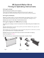
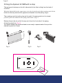
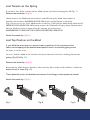
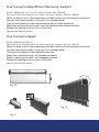
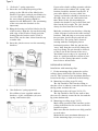
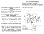
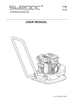
Type 1
SR Series® Roller Blind
Fit t ing & Operat ing Inst ruct ions
SR Series® Roller Blind
Fit t ing & Operat ing Inst ruct ions
Fit t ing t he blind
Caref ully unwrap t he blind f rom it s wrapping.
Then check t he bracket s as t hese could be a dif ferent st yle for each end.
The bracket s are unive rsal and can be fixed in a top, faced or side fixed posit ion.
Fit t ing t he bracket s
Measure t he f abric widt h of t he roller blind and place your bracket 35mm (1.375”)
wider t han t his me asure me nt wit h t wo screws in e ach bracket , making sure t he
bracket s are correct for t hat side of t he blind and are level.
Fit t ing t he Syst em 32 SR® wit hout a st op
The spring end is always on t he lef t side and wit h t he f abric rolling f rom t he back of t he
blind.
Wit h t he blind rolle d in t he upper most posit ion push fit t he blind into t he opposit e e nd
bracket f rom t he spring. (Fig.1)
Then making sure t he locat ing lugs on t he e nd of t he spring side is in t he lowest posit ion,
(Fig. 2) place t he blind into t he spring end bracket .
Release t he pin (do not pull all t he way out ) f rom t he f ront side of t he spring.
At t ach t he met al clip. (Fig. X)
Your blind has been pre-t ensioned and is now ready to operat e. (Fig.3)
Fig. 1
Fig. 2
Fig. 3
Type 2
Fit t ing t he Syst em 32 SR® wit h a st op
The spring end is always on t he lef t side and wit h t he f abric rolling f rom t he back of
t he blind.
Wit h t he blind rolle d in t he uppe r most or at t he de sire d top he ight posit ion, push fit t he
blind into t he stop end which is opposit e end bracket f rom t he spring. (Fig.4)
Then making sure t he locat ing lugs on t he end of t he spring side is in t he lowest
posit ion, place t he blind into t he spring e nd bracket . (Fig.5 )
Release t he pin (do not pull all t he way out ) f rom t he f ront side of t he spring.
At t ach t he met al clip. (Fig. X)
Your blind has been pre-t ensioned and is now ready to operat e and will stop at t he
desired top posit ion. (Fig.6)
Fig. 4
Fig. 5
Fig. 6
Lost Tension on t he Spring
If you have lost all t he t ension on t he blind, ensure t he front locat ing pin is IN (Fig. 7 ).
Remove t he met al clip. (Fig. X)
Gent ly remove t he blind from t he bracket s and roll back up by hand, t he n re place it
back into t he bracket s AND RELEASE THE PIN (Fig.8 ) and pull down to t he drop,
(Fig 9 ) t he n t est to se e if t he blind ret urns to t he top, if not pull t he blind down and lock off,
DEPRESS THE LOCKING PIN AND gent ly remove t he blind and roll up by hand. Re place back
into t he bracket s and t est again wit h t he locat ing pin at t he front ,
REMEMBERING TO RELEASE THE LOCKING PIN BEFORE OPERATION.
At t ach t he met al clip. (Fig. X)
Lost Top Posit ion on t he Blind
If your blind has a top stop in it and you lose t he posit ion of t he top stop and t he
f abric is not stopping at t he desired raised posit ion and it is cont inuing going round
t he t ube, it can be reset .
To reset , lock t he blind at t he desired raised posit ion t hen insert t he locking pin into t he
spring. (Fig.10 & Fig. 11)
Remove t he met al clip. (Fig. X)
Re moving t he blind from it s bracket s, t he n t urn t he idle end pin of t he blind in a clockwise
direct ion unt il it stops (Fig. 12)
Then replace blind into t he bracket s and remove t he locking pin and operat e as normal.
At t ach t he met al clip. (Fig. X)
Fig. 7
Fig. 8
Fig. 9
Fine Tuning t he Drop Wit hout Removing t he Blind
Pull t he blind down to t he neare st posit ion of t he drop required.
Now push in t he locat ing pin at t he front end of t he spring to lock t he blind off
Whilst t he blind is st ill in t he bracket s grip t he f abric sect ion of t he blind push t he blind to
t he right side 3mm (normally to t he right if in a st andard blind)
Then you will be able to rot at e t he blind eit her way in 20mm increment s
Rot at e t his and t he blind will move to suit t he new drop t hen release t he blind
Release t he locat ing pin at t he f ront of t he blind
Operat e t he blind as normal
Fine Tuning t he Speed
Pull t he blind down half way
Now push in t he locat ing pin at t he front end of t he spring to lock t he blind off
Whilst t he blind is st ill in t he bracket s grip t he f abric sect ion of t he blind push t he blind to
t he right side 3mm (normally to t he right if in a st andard blind)
Then you will be able to rot at e t he blind eit her way
Rot at e t his towards you and it will increase t he speed.
Rot at e it away f rom you and it will decrease t he speed
Release t he locat ing pin at t he f ront of t he blind
Operat e t he blind as normal
Fig. 10
Fig. 12
Fig. 11
Type 3
3. “Soft-raise” spring operation
3a. Insert the cross-shaped opening of the
spring, on the LH side of the blind in the
bracket. If you have ordered your blind to be
“reverse rolled” (cloth rolling to room side),
the cross shaped opening should be
mounted to the RH bracket. (The positioning
of the cross onto the brackets is not
important).
3b. Bring the bearing end of the blind to the lip
of the bracket. Align the slot on the bearing
with edge of the bracket. Gently push the
bearing into the bracket until a ‘click’ is
heard. This can be done either from the top
or under side.
3b. Insert the plastic covers over the mounting
brackets.
3a
3b
If your roller cloth is rolling upwards with the
fabric nearest the window, the ' spring' end
bracket should be mounted on the left. If
your roller fabric is ' reverse rolled' the
' spring' end bracket should be mounted on
the right. Note: the ' pin' end bracket has
three holes for the pin, depending on
whether the bracket is top or face fixed and
fitted on the left or right. The ' pin' should
always be fitted into the lower hole.
Mark the position of your brackets, allowing
a little clearance between the roller and the
brackets. Drill and plug as necessary and fix
into position. Locate the pin end into it' s
bracket first. The spring end is located
starting with the rectangular pin in a
horizontal position. Slide the pin into the
' cross' hole from the rear if face fitting, the
top if top fixing. The pin should be located
so that it sits in the bottom of the cross.
Your blind is now ready to be operated. If
there is a problem with the tension of your
roller, see the ' Spring Operation' section
later in these instructions.
INSTALLATION OPTIONS
Installation with mounting clips
3c
5. Fix the mounting clips against the wall or
ceiling (always drill holes first, before fixing
screws). Take account of the maximum distances
between the clips, as indicated in the drawing.
5a. Mounting to ceiling (type 20 only)
The clip should be fixed on the ceiling so
that the screw is (almost) centred in the slot and
the lip points towards the rear.
4. ‘Non Softraise’ spring operation
You will have been supplied with two
brackets. A' pin' end bracket (4a) an a
'spring' end bracket (4b).
4a
4b
5b. Mounting to the wall (type 20/ 30/ 35)
The clip should be fixed to the wall so that
the screw is (almost) centred in the slot and the
lip points downwards.
5c. Mounting to ceiling (type 30/ 35)
Mark off the position of the brackets on the
ceiling, drill holes for the screws and fix the
brackets in place.
Make sure that the brackets are fully parallel
to each other.
Maintain the same maximum distances as
for the mounting clips (see steps 4-5).