1
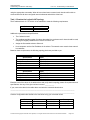
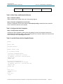
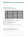
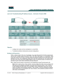
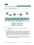
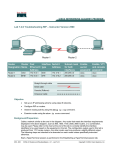
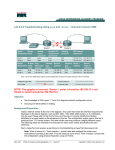
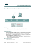
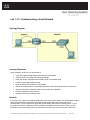
Lab 1.3.3: Troubleshooting a Small Network
Topology Diagram
Learning Objectives
Upon completion of this lab, you will be able to:
•
Verify that a paper design meets stated network requirements
•
Cable a network according to the topology diagram
•
Erase the startup configuration and reload a router to the default state
•
Load the routers with supplied scripts
•
Discover where communication is not possible
•
Gather information about the misconfigured portion of the network along with any other errors
•
Analyze information to determine why communication is not possible
•
Propose solutions to network errors
•
Implement solutions to network errors
Scenario
In this lab, you are given a completed configuration for a small routed network. The configuration contains
design and configuration errors that conflict with stated requirements and prevent end-to-end
communication. You will examine the given design and identify and correct any design errors. You will
then cable the network, configure the hosts, and load configurations onto the router. Finally, you will
troubleshoot the connectivity problems to determine where the errors are occurring and correct them
All contents are Copyright © 1992–2007 Cisco Systems, Inc. All rights reserved. This document is Cisco Public Information.
Page 1 of 5
CCNA Exploration
LAN Switching and Wireless: LAN Design
Lab 1.3.3: Troubleshooting a Small Network
using the appropriate commands. When all errors have been corrected, each host should be able to
communicate with all other configured network elements and with the other host.
Task 1: Examine the Logical LAN Topology
The IP address block of 172.16.30.0 /23 is subnetted to meet the following requirements:
Subnet
Subnet A
Subnet B
Number of Hosts
174
60
Additional requirements and specifications:
•
The 0 subnet is used.
•
The smallest possible number of subnets that satisfy the requirements for hosts should be used,
keeping the largest possible block in reserve for future use.
•
Assign the first usable subnet to Subnet A.
•
Host computers use the first IP address in the subnet. The network router uses the last network
host address.
Based on these requirements, the following topology has been provided to you:
Subnet A
Specification
IP mask (decimal)
IP address
First IP host address
Last IP host address
Value
255.255.255.0
172.16.30.0
172.16.30.1
172.16.30.254
Subnet B
Specification
IP mask (decimal)
IP address
First IP host address
Last IP host address
Value
255.255.255.128
172.16.31.0
172.16.31.1
172.16.31.126
Examine each of the values in the tables above and verify that this topology meets all requirements and
specifications. Are any of the given values incorrect? ___________
If yes, correct the values in the table above and write the corrected values below:
______________________________________________________________________________
______________________________________________________________________________
Create a configuration table similar to the one below using your corrected values:
Device
Host1
Router1–Fa0/0
Host2
IP address
172.16.30.1
172.16.30.254
172.16.31.1
Mask
255.255.255.0
255.255.255.0
255.255.255.128
Gateway
172.16.30.254
N/A
172.16.31.126
All contents are Copyright © 1992–2007 Cisco Systems, Inc. All rights reserved. This document is Cisco Public Information.
Page 2 of 5
CCNA Exploration
LAN Switching and Wireless: LAN Design
Router1–Fa0/1
Lab 1.3.3: Troubleshooting a Small Network
172.16.31.126
255.255.255.128
N/A
Task 2: Cable, Erase, and Reload the Routers
Step 1: Cable the network.
Cable a network that is similar to the one in the topology diagram.
Step 2: Clear the configuration on each router.
Clear the configuration on the router using the erase startup-config command and then reload the
router. Answer no if asked to save changes.
Task 3: Configure the Host Computers
Step 1: Configure host computers.
Configure the static IP address, subnet mask, and gateway for each host computer based on the
configuration table created in Task 1. After configuring each host computer, display and verify the host
network settings with the ipconfig /all command.
Task 4: Load the Router with the Supplied Scripts
enable
!
config term
!
hostname Router1
!
enable secret class
!
no ip domain-lookup
!
interface FastEthernet0/0
description connection to host1
ip address 172.16.30.1 255.255.255.0
duplex auto
speed auto
!
interface FastEthernet0/1
description connection to switch1
ip address 192.16.31.1 255.255.255.192
duplex auto
speed auto
!
!
line con 0
password cisco
login
line vty 0
login
All contents are Copyright © 1992–2007 Cisco Systems, Inc. All rights reserved. This document is Cisco Public Information.
Page 3 of 5
CCNA Exploration
LAN Switching and Wireless: LAN Design
Lab 1.3.3: Troubleshooting a Small Network
line vty 1 4
password cisco
login
!
end
Task 5: Identify Connectivity Problems
Step 1: Use the ping command to test network connectivity.
Use the following table to test the connectivity of each network device.
From
To
IP Address
Host1
NIC IP address
Host1
Router1, Fa0/0
172.16.30.1
172.16.30.254
Host1
Router1, Fa0/1
172.16.31.126
Host1
Host2
172.16.31.1
Host2
NIC IP address
172.16.30.1
Host2
Router1, Fa0/1
172.16.31.126
Host2
Router1, Fa0/0
172.16.30.254
Host2
Host1
172.16.30.1
Ping Results
Task 6: Troubleshoot Network Connections
Step 1: Begin troubleshooting at the host connected to the BRANCH router.
From host PC1, is it possible to ping PC2? _________
From host PC1, is it possible to ping the router fa0/1 interface? _________
From host PC1, is it possible to ping the default gateway? _________
From host PC1, is it possible to ping itself? _________
Where is the most logical place to begin troubleshooting the PC1 connection problems?
_________________________________________________________________________________
_________________________________________________________________________________
Step 2: Examine the router to find possible configuration errors.
Begin by viewing the summary of status information for each interface on the router.
Are there any problems with the status of the interfaces?
_________________________________________________________________________________
_________________________________________________________________________________
All contents are Copyright © 1992–2007 Cisco Systems, Inc. All rights reserved. This document is Cisco Public Information.
Page 4 of 5
CCNA Exploration
LAN Switching and Wireless: LAN Design
Lab 1.3.3: Troubleshooting a Small Network
If there are problems with the status of the interfaces, record any commands that are necessary to correct
the configuration errors.
___________________________________________________________________________________
___________________________________________________________________________________
Step 3: Use the necessary commands to correct the router configuration.
Step 4: View a summary of the status information.
If any changes were made to the configuration in the previous step, view the summary of the status
information for the router interfaces.
Does the information in the interface status summary indicate any configuration errors on Router1?
_______
If the answer is yes, troubleshoot the interface status of the interfaces.
Has connectivity been restored? ________
Step 5: Verify the logical configuration.
Examine the full status of Fa 0/0 and 0/1. Is the IP addresses and subnet mask information in the
interface status consistent with the configuration table? _______
If there are differences between the configuration table and the router interface configuration, record any
commands that are necessary to correct the router configuration.
____________________________________________________________________________________
____________________________________________________________________________________
Has connectivity been restored? ________
Why is it useful for a host to ping its own address?
____________________________________________________________________________________
____________________________________________________________________________________
Task 7: Clean Up
Unless directed otherwise by your instructor, erase the configurations and reload the switches.
Disconnect and store the cabling. For PC hosts that are normally connected to other networks (such as
the school LAN or to the Internet), reconnect the appropriate cabling and restore the TCP/IP settings.
All contents are Copyright © 1992–2007 Cisco Systems, Inc. All rights reserved. This document is Cisco Public Information.
Page 5 of 5