1
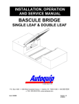
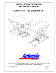
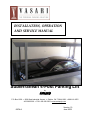
INSTALLATION, OPERATION AND SERVICE MANUAL Subterranean 4-Post Parking Lift by Autoquip P.O. Box 1058 1058 West Industrial Avenue Guthrie, OK 73044-1058 888-811-9876 405-282-5200 FAX: 405-282-3302 www.autoquip.com 830VL4 Version 1.0 June 2009 © 2009 AUTOQUIP CORPORATION This manual and the information herein is the sole property of Autoquip Corp. and shall not be reproduced without written consent by Autoquip 2 TABLE OF CONTENTS Introduction 4 Responsibility of Owners/Users 5 Pre-Installation Site Visit 6 Safety Signal Words 7 Safety Practices 8 Safety Features 12 Label Identification 15 Specifications 19 Blocking Instructions 20 Installation Instructions 22 Operating Instructions 51 Routine Maintenance 53 General Maintenance 55 Replacement Parts List 62 Troubleshooting Analysis 64 Glossary of Terms 69 IMPORTANT Please read and understand this manual prior to operation of your 4-Post Parking Lift. Failure to do so could lead to property damage and/or serious personal injury. If any questions should arise, call a local representative or Autoquip Corporation at 1-888-8119876 or 405-282-5200. PLANNED MAINTENANCE PROGRAM A local Autoquip representative provides a Planned Maintenance Program (PMP) for this equipment using factory-trained personnel. Call a local representative or Autoquip Corporation at 1-888-811-9876 or 405-282-5200 for more information. 3 INTRODUCTION Autoquip Corporation has manufactured this product to move vehicles between floors or levels safely and efficiently. It has been built to provide many years of dependable service. Proper installation of this equipment is vital to both the efficiency of the unit and the ultimate satisfaction of the end user. It is vital for the installers to read and understand this manual! These instructions have been prepared and organized to assist the installers and it is important for these individuals to carefully follow the steps in the order they are presented! Situations may arise which are not covered in these installation instructions. If you have questions, please call Autoquip Customer Service at (405) 282-5200 or 1-888-8119876. NOTE: Unless otherwise stated, mechanical installation does not include unloading, permits, seismic calculations, or extensive acceptance testing. The requirements of each contract should be carefully reviewed for possible conflicts of interpretation. UPON DELIVERY OF THE EQUIPMENT Upon receipt of the shipment, check for exposed damage or shortages and make note of it on the trucking company Bill of Lading or the Shipping Papers. Reports of concealed damage to items contained in crates must be reported within 48 hours. DO NOT destroy the crating while opening it to inspect the contents. If damage is suspected or found, report it directly to the carrier. DO NOT contact Autoquip Corporation!! All shipments are FOB from the Autoquip plant. Any claims for damage must be filed with the carrier. Any parts shipped from Autoquip that are intended to replace damaged or lost items will be invoiced to the ordering party. Assuming no damage has occurred to the crate, check the components against the packing list. This will provide assurance that every item shipped has been received. Everything needed for the installation should be available. If not, report any shortages to Autoquip Corporation within 10 days. (Autoquip is not responsible for parts lost, stolen or damaged during transportation, storage, installation, or during any other circumstances or conditions that may be beyond corporate control.) 4 RESPONSIBILTY OF OWNERS/USERS DEFLECTION Deflection is normal and is to be expected when the lift is placed under load. It is the responsibility of the user/purchaser to advise the manufacturer where deflection may be critical to the application. INSPECTION & MAINTENANCE The lift shall be inspected & maintained in proper working order in accordance with Autoquip’s operating/maintenance (O&M) manual and safe operating practices. REMOVAL FROM SERVICE Any lift not in safe operating condition such as, but not limited to, excessive leakage, missing pins, or fasteners, any bent or cracked structural members, cut or frayed electric, hydraulic, or pneumatic lines, damaged or malfunctioning controls or safety devices, etc. shall be removed from service until it is repaired to the original manufacturer’s standards. REPAIRS All repairs shall be made by qualified personnel in conformance with Autoquip’s instructions. OPERATORS Only trained personnel and authorized personnel shall be permitted to operate the lift. BEFORE OPERATION Before using the lift, the operator shall have: Read and/or have explained, and understood, the manufacturer’s operating instructions and safety rules. Inspect the lift for proper operation and condition. Any suspect item shall be carefully examined and a determination made by a qualified person as to whether it constitutes a hazard. All items not in conformance with Autoquip’s specification shall be corrected before further use of the lift. DURING OPERATION The lift shall only be used in accordance with Autoquip’s O&M manual. Do not overload the lift. Ensure that all safety devices are operational and in place. MODIFICATIONS OR ALTERATIONS Modifications or alterations to industrial lifting equipment shall be made only with written permission of Autoquip. Autoquip does not foresee and does not anticipate unauthorized modifications, and these changes or alterations are grounds for voiding all warranties. 5 PRE-INSTALLATION SITE VISIT SITE CONDITIONS Whenever possible, make a pre-installation visit or call someone at the site. Installers must be familiar with everything relative to proper installation of this equipment. Some concerns are listed below, though listing every affecting contingency is impossible. It is the installer’s responsibility to check the site for problems and work out solutions with the appropriate people. Some of the areas of concern are: 1. Is the site accessible to large delivery & cartage vehicles? 2. Can the lift components get through the existing doorways & floor openings? 3. How will the unit be raised, set into position, and accessed? 4. Can a chain fall be hooked to an available overhead support? 5. Is there a forklift or other cartage equipment available? 6. Is there adequate building structure to support vertical guides? 7. Look for problem areas such as bracing and overhead interference with ceilings, joists, pipes, etc.. It is always best to be prepared, so do as much pre-planning as possible before the installation procedure actually begins. Learn about the site, the equipment, and the installation process. 6 SAFETY SIGNAL WORDS SAFETY ALERTS (Required Reading!) The following SAFETY ALERTS are intended to create awareness of owners, operators, and maintenance personnel of the potential safety hazards and the steps that must be taken to avoid accidents. These same alerts are inserted throughout this manual to identify specific hazards that may endanger uninformed personnel. Identification of every conceivable hazardous situation is impossible. Therefore, all personnel have the responsibility to diligently exercise safe practices whenever exposed to this equipment. ____________________________________________________________ DANGER! Identifies a hazardous situation which, if not avoided, will result in death or severe personal injury. _____________________________________________________________ WARNING! Identifies a hazardous situation which, if not avoided, could result in death or serious personal injury. CAUTION! Identifies a hazardous situation which, if not avoided, may result in minor or moderate personal injury. _____________________________________________________________ NOTICE Identifies a potentially hazardous situation which, if not avoided, may result in property or equipment damage. ____________________________________________________________ 7 SAFETY PRACTICES DANGER! High voltage! Repairs should only be performed by a qualified service/control technician!! DANGER! Never go under a platform! To avoid personal injury or death, always be sure the load has been removed from the platform and that it has been blocked from underneath! See “Blocking Instructions” section. DANGER! Qualified personnel only!! Only qualified service personnel should perform procedures labeled as “dangerous”! DANGER! Be sure of equipment stability! To avoid personal injury or death, check for stability. If the unit seems unstable, do not operate! Contact Autoquip immediately! DANGER! Turn off power during inspection & maintenance! To avoid personal injury or death, be sure the power is off and is locked per OSHA Lock-out, Tag-out procedures! 8 SAFETY PRACTICES DANGER! Practice field safety procedures! To avoid personal injury or death, utilize all applicable precautions for steel erection and equipment assembly in addition to OSHA regulations for lock-out, tag-out, etc.! DANGER! Secure platform and cylinders! Do not remove or disconnect the power unit unless the platform and cylinders have been secured and all hydraulic pressure has been relieved. See “Blocking Instructions” section. WARNING! No riders! Parking Lifts are designed for the sole purpose of transporting vehicles between floor elevations. At no time should it be used to transport personnel!! WARNING! Never run the unit with the gates or doors open! Do not operate unit with doors open or with the interlocks or other safety devices and sensors “defeated” (bypassed)! Serious injury or death could result. WARNING! Velocity fuse lock-up requires factory help! Contact your local Vehicle Lift representative or call Autoquip Service Department if hydraulic velocity fuses should lock up! 9 SAFETY PRACTICES WARNING! Secure unit before making static inspections! Make sure the platform is fully lowered and the power is turned off (disconnected at the safety disconnect switch) before performing static inspections. Place signs at all gates, doors, controls, etc. indicating the system is temporarily out of service for routine maintenance per OSHA requirements for Lock-Out, TagOut. WARNING! Never operate unit when parts are defective! Do not operate this equipment when damaged, substandard or defective parts are in use! Contact an Autoquip Service Representative to rectify all such situations. WARNING! Use high pressure hydraulic components only! Never use fittings or hoses that are not properly rated for 3,000 psi service. WARNING! Use approved or prescribed procedures only! If any procedure prescribed in this manual cannot be followed or adhered to for any reason, IMMEDIATELY cease what is being done and contact an Autoquip Service Representative for assistance. Autoquip can not foresee the possible misuses of this equipment caused as a result of not following prescribed installation, operation, and maintenance procedures. 10 SAFETY PRACTICES WARNING! The velocity fuse (VF) must be properly installed! The VF is attached directly to the rod port of the cylinder. If the VF is installed improperly, it will not lock up in the event of a catastrophic hydraulic line break! CAUTION! Do not run carriage until limit switch is set! If the electrical work is not complete, do not run the carriage all the way to the top until the limits are set. NOTICE Use appropriate fluids! Do not use automatic transmission fluid (ATF), hydraulic jack oil, hydraulic fluids, or brake fluids in the power unit or hosing system. Use 5W30 motor oil or other approved fluids only. NOTICE Keep power unit filled! Do not run the hydraulic power unit dry. Damage to the pump and motor may result. NOTICE Do not operate motor at relief pressure! The motor should not be operated for more than a few seconds when the unit is operating at relief pressure. Longer running times could result in damage to the pump. NOTICE Avoid air in the system! The presence of air in the system can lead to a lock-up of the velocity fuses. (Air reacts like a spring when it is compressed.) 11 SAFETY FEATURES There are several primary active safety features and devices to help protect personnel, property, and the equipment. HYDRAULIC VELOCITY FUSES Each hydraulic cylinder has a hydraulic velocity fuse (HVF) installed in the cylinder port. These HVFs are installed in the predetermined hydraulic oil flow velocity as the oil returns to the reservoir. They do not affect incoming oil. Should a catastrophic rupture or breach occur in the hydraulic system and oil flows through the breach that exceeds the HVF rating, the HVF will trigger and lock up. This lock up will occur with one to two inches of downward movement of the platform carriage. NOTE: Air in the system will also cause a lock up. Air acts like a spring when compressed. To remove air from the system, see “Air Bleeding Procedures” in the General Maintenance section. NOTE: Small fitting or hose leaks will not trigger the HVFs. In an air-free system, the breach must be large enough to cause an uncontrolled or destructive lowering speed. Should a triggering and lock-up occur, it can only be released by applying hydraulic flow and pressure to a functional system. SAFETY RELEASE BYPASS VALVE (SRBV) The SRBV is a part of the hydraulic system. Should the system pressure exceed the predetermined pressure setting, the SRBV will bypass the pump output back to the oil reservoir. The SRBV is factory set to the proper pressure, which will prevent damage to the mechanical, hydraulic, and electrical systems due to overloading, obstruction, or other circumstances. MOTOR STARTER OVERLOADS (MSO) These are current sensing devices that are located in the two legs of the electric motor primary power circuit (208/230 volt). They protect the motor from excessive current draw if it becomes overloaded, experiences low line voltage, or has a short circuit. Should either leg sense an over-current situation the element will heat up and trip the heat sensitive device housed in the motor starter coil circuit. Power is removed to the coil and the two line power contacts are opened in the motor primary power circuit. This will stop the motor from rotating until the overloads are reset and/or the fault is cleared which caused the trip condition. NOTE: The MSO will only affect the “UP” circuit. The platform carriage can be lowered if the MSO trips. 12 SAFETY FEATURES CONTROL TRANSFORMER SECONDARY FUSE This fuse is attached to the electrical control transformer and protects the 24 volt control circuit from damage should a fault occur which would result in excessive electric current flow. Should the fuse activate (blow) it will prevent the operation in either direction and the interlock circuit will not operate (doors won’t lock). These fuses are located in the control enclosure. DANGER! High voltage! Repairs should only be performed by a qualified electrician or service technician and OSHA requirements for LockOut, Tag-Out must be followed!! SAFETY INTERLOCKS/LATCHES-GATES OR DOORS (optional – used where applicable) These are electro/mechanical devices that prevent operation of the vehicle lift when the gates or doors are left open on any level. They also prevent the gates or doors from being opened whenever the lift is in motion. WARNING! Never run the unit with the gates or doors open! Do not operate unit with doors open or with the interlocks “defeated” (bypassed)! BEVELED TOE GUARDS (BTG) Fixed mechanical toe guards are welded around the perimeter of the top canopy at an angle of approximately 30 degrees from vertical to protect toes during operation as this deck descends past the edge of the garage floor into home position. KEY LOCK-OUT STATION Separate electrical device which requires a key to turn the control system “On”. This station is shipped loose and is wired in the circuit between the control panel and the operator pushbutton station to prevent unauthorized operation of the lift. E-STOP STATION (optional) Emergency Stop “panic” button which, when pushed, removes electrical power from the control circuit and immediately stops lift movement. E-Stop stations can be located at upper or lower level locations, and must be manually reset to continue operation. 13 SAFETY FEATURES KEY PAD STATION (optional) A key pad security station can be purchased in lieu of a keyed security station to turn the control system “On”. This station is shipped loose and is wired in the circuit between the control panel and the operator pushbutton station to prevent unauthorized operation of the lift. ADJUSTABLE WHEEL STOPS (optional) These mechanical devices can be adjusted to help ensure that a vehicle being parked on the lower deck for storage is located completely within the perimeter of the deck so as to prevent damage to the vehicle or the lift as the vehicle is lowered from the upper level to the lower level. ULTRASONIC VEHICLE POSITION INDICATOR (optional) This simple, electronic device mounts to a wall in front of the lift and can be adjusted to ensure that a vehicle being parked on the lower deck for storage is located completely within the perimeter of the deck so as to prevent damage to the vehicle or the lift as the vehicle is lowered from the upper level to the lower level. VEHICLE-PRESENT SENSORS (optional) These photo-eye sensors look across the upper deck of the lift when it is in the home or fully lowered position to “see” whether a vehicle is present on the deck or not. If a vehicle is sensed, the photo-eye switch opens a contact in the control circuit and operator will not be able to activate the “UP” button to raise the deck . PLATFORM MOVEMENT ALARM (optional) An audible and/or visual signaling device which will activate any time the “UP” or “DOWN” pushbutton is pressed to notify anyone in the area that the lift is being operated. PHOTO EYE INTERFERENCE DETECTION (optional) These photo-eye sensors look across an edge of the lift to detect any type of potential interference from items that would get close enough to break the photo eye beam. If broken, the photo-eye switch opens a contact in the control circuit and operator will not be able to operate the lift. 14 LABEL IDENTIFICATION 4 1 5 3 1 058 W. Industr ial Ave . Guthr ie , OK 7 304 4-10 58 8 88-8 11-9 876 www.autoquip.com 2 ,000 LBS. CAPACITY 1 5 1 058 W. Industrial Ave . Guthrie, OK 73 044 -105 8 8 88-8 11-98 76 www.autoquip.com 3 640 159 4 ,000 LBS. CAPACITY 3 640 159 4 99 WARNI NG 1. FAMILIARIZE OPERATORS YOURSELF OPERATING 2. OPERATOR AREA ONLY IN THE 3. REMAIN DURING OPERATION 4. NEVER EXCEED 5. IF ANY LIFT IS DEFECTIVE BELIEVED TO - 6 7 6 7 LIF 6. ALWAYS ENGAGED ATTEMPT IS BEFORE ON ORANY BENEATH 7. FAILURE TO FOLLOW SEVERE PERSONAL 3640 3993 8 Figure 1 Label Placement Diagram 4-Post Subterranean Lift Item No. Qty Description Part No. 1 2 3 4 5 6 7 8 9 4 2 2 2 4 4 4 1 2 Caution! Familiarize Yourself With Operators Manual Danger – Do Not Put Hands or Feet… Autoquip Serial Number Nameplate Autoquip Logo Capacity Maintenance Device Maintenance Device Socket WARNING! Do Not Tamper Operator Warning Placard (shipped loose) 36401487 36430050 36401560 36403225 36401594 36400257 36400265 36405695 36403993 15 LABEL IDENTIFICATION Note: Labels shown here are not actual size. Figure 2 Label 36401487 Figure 3 Label 36430050 Figure 4 Label 36401560 Figure 5 Label 36403225 16 LABEL IDENTIFICATION Figure 6 Label 36401594 Figure 7 Label 36400257 Figure 8 Label 36400265 Field-locate & apply one “WARNING – Do Not Tamper” label adjacent to (within 6”-12”) each sensing device (limit switches, door status switches, door interlocks, etc.) in a location that is visible to the operator. Figure 9 Label 36405695 17 LABEL IDENTIFICATION WARNING 1. FAMILIARIZE YOURSELF WITH OPERATORS MANUAL BEFORE OPERATING THIS LIFT. 2. OPERATOR ONLY IN THE LIFT AREA DURING OPERATION. 3. REMAIN CLEAR OF LIFT DURING OPERATION. Field-locate & apply this decal adjacent to the lift at each level, ideally in the vicinity of the operator pushbutton station. 4. NEVER EXCEED RATED CAPACITY OF LIFT. 5. IF ANY COMPONENT OF THIS LIFT IS BELIEVED TO BE DEFECTIVE - DO NOT OPERATE LIFT. 6. ALWAYS ENSURE MAINTENANCE DEVICES ARE ENGAGED BEFORE ANY ATTEMPT IS MADE TO WORK ON OR BENEATH LIFT. 7. FAILURE TO FOLLOW THESE INSTRUCTIONS CAN RESULT IN SEVERE PERSONAL INJURY OR DEATH. 36403993 Figure 10 Label 36403993 18 SPECIFICATIONS General Specifications: VL4 – Subterranean 4Post Lift Model Lifting Lowered Travel Capacity Height (in) (lbs.) (in) Standard Platform (Vehicle Clearance) (inches) Maximum Axle Load Over End (lbs) HP 230V 1ph Up Speed 2.25gpm (sec) Down Speed 4.5gpm (sec) Maximum Total Floor Shipping Pressure Weight (psi) (lbs.) 96VL4-70 96 7,000 18 108 x 216 (100W x 90H) 4,000 5 78 39 112 7,500 96VL4-140 96 14,000 18 108 x 216 (100W x 90H) 4,000 5 107 53 160 7,500 108VL4-70 108 7,000 18 108 x 216 (100W x 102H) 4,000 5 88 44 112 7,600 108VL4-140 108 14,000 18 108 x 216 (100W x 102H) 4,000 5 120 60 160 7,600 120VL4-70 120 7,000 18 108 x 216 (100W x 114H) 4,000 5 133 67 112 7,700 120VL4-140 120 14,000 18 108 x 216 (100W x 114H) 4,000 5 174 87 160 7,700 132VL4-70 132 7,000 18 108 x 216 (100W x 126H) 4,000 5 147 73 112 7,800 132VL4-140 132 14,000 18 108 x 216 (100W x 126H) 4,000 5 192 96 160 7,800 144VL4-70 144 7,000 18 108 x 216 (100W x 138H) 4,000 5 209 104 112 7,900 144VL4-140 144 14,000 18 108 x 216 (100W x 138H) 4,000 5 209 104 160 7,900 This lift is designed to accommodate personal vehicles with normal axle loads and weight distributions for such. Standard parking lifts are not designed to withstand single axle loads greater than 4,000 lbs. at the front edge of the lift or a weight distribution that exceeds more than a 60/40 difference in total vehicle weight from front to back. This lift is not an automobile elevator and is not designed to meet the requirements of ASME A17.1 – Safety Code for Elevators and Escalators. 19 BLOCKING INSTRUCTIONS DANGER! Never go under a platform! To avoid personal injury or death, always be sure the load has been removed from the platform and that it has been blocked from underneath! NOTE: The Maintenance Devices are designed to rest on the garage floor at the upper level, therefore maintenance and inspection can be safely performed only with the lift in the fully raised (on the maintenance devices) or fully lowered (on the landing legs) positions. 1. Send the lower deck to the fully raised position, then remove all four (4) maintenance devices from their stored location and place them in the fully engaged position (see Fig. 11). 2. Remove all load from the unit. 3. Lower the empty deck until ALL four (4) maintenance devices make contact with the surrounding floor. 4. Lock out and tag the electrical disconnect 5. As an added level of protection when using the locking devices at floor level, it is recommended that a secondary set of stops be placed underneath the lower deck such as four (4) 4” x 4” treated wood posts that have been cut to the appropriate length to place one end on the floor and wedge the other end between each corner guide angle and the lift deck. DANGER! To avoid personal injury or death, check the stability of the supports. If there is any chance of the support tipping or otherwise not providing a safe and stable condition, do not go under the platform! Contact an Autoquip service representative for assistance! 6. When inspection or repair is complete, remove 4” x 4” timbers from beneath the lift. 7. Unlock electrical disconnect, raise lift to fully raised position. 8. Return maintenance devices to stored position. 20 BLOCKING INSTRUCTIONS DANGER! To avoid personal injury or death, turn off the power and lock out the power at the primary power disconnect switch per OSHA LockOut, Tag-Out requirements before service or maintenance is performed. Figure 11 Maintenance Devices – Typical (4) Corners 21 INSTALLATION INSTRUCTIONS THE TOOLS REQUIRED FOR INSTALLATION Listed below are some of the tools typically needed to install a vehicle lift in a professional and prompt manner. Individual site situations and a basic variation in the types of units may dictate the need for additional items. Welding Machine and Equipment Cutting Torch with Full Tanks Fire Extinguisher Forklift or Small Crane Nylon Slings Saw Horses Cables or Hook Chains with 1,000# Cap. Disk Grinder “C” Clamps Socket Set (1/2” drive, sockets to 1 1/8”) Pinch Bar Hammer Drill & Bits for 1/4”, 3/8” and 1/2” anchors Extension Cords Hack Saw, Sawzall, or Portable Band Saw Chain Pulling Tool Drill and Drill Bits Sledge Hammer Open or box end wrench Drift Punch Carpenter’s Square Chalk Line Plumb Bobs Laser Level 25’ Measuring Tape Broom The following supplies will also be needed: *Concrete anchors sized for the required minimum pullout of the corner guide floor plates and connection to the garage floor opening. Refer to the approval drawing since the size of the anchors can vary for each installation. *Shim stock for the guide angle floor mounting & wall mounting *Hydraulic oil (see oil recommendations and tank capacity in the “Specifications” section) 22 INSTALLATION INSTRUCTIONS RIGHT SIDE OF LIFT REAR OF LIFT LEFT SIDE OF LIFT Figure 12 Corner Reference – For Clarity Throughout the Install Process 23 INSTALLATION INSTRUCTIONS GENERAL (Reference the General Arrangement Drawing – sent separately) Please refer to the General Arrangement (GA) or Record Drawings that have been shipped with the lift. These drawings have notes and measurements that should be checked before installation of the lift. The drawings will show how the lift should be arranged and how it should be installed specifically for this application. The installation may begin only after all of the measurements have been checked and are correct (floorto-floor distances, pit depth, upper level opening, overhead clearances, etc.). NOTE: All illustrations contained in this manual are for reference purposes only. Specific applications and site conditions may require different anchoring and bracing procedures. The ultimate responsibility for the anchoring and bracing rests with the installation crew. A. MOUNTING THE VERTICAL (CORNER) GUIDE ANGLES (Reference Fig.13) Items needed for this step: Qty Description 4 Corner Guide Weldments 1. Mount each corner guide weldment in its appropriate corner and at the appropriate distances apart as shown in the GA Drawing. 2. Double-check all clearances (side-to-side & end-to-end) between the guide angle surfaces, then attach each guide into the wall and floor using the required number of lag bolts for each – sized to withstand the pull-out force specified on the GA drawing. Hand snug these anchor bolts only, do not tighten at this time. 3. Recheck the position of the guides and ensure that they are also plumb, parallel, square, and level (guides must be checked closely for level because pit floors & walls may not be poured level). To maintain proper positioning of the guides throughout lift travel – shim under each foot plate as required to fill any gaps between the foot plate and the floor or the wall plate and the wall which may have been created during the plumb-square-level process. NOTE: Guides must be plumb and parallel within 1/8” before proceeding with installation 4. Tighten all bolts to 50 ft-lbs torque. 24 INSTALLATION INSTRUCTIONS GARAGE FLOOR OPENING Lagging Locations Chromed Cylinder Rod Right Rear Guide Angle Figure 13 Corner Guide Installation 25 INSTALLATION INSTRUCTIONS B. ATTACHING THE CANOPY POSTS (Reference Figure 14) Items needed for this step: Description Qty 4 Square Tube Canopy Posts w/Maintenance Device 16 1/2"-13 x 1” Long Hex Head Bolts, Grade 5 16 1/2" Flat Washers 16 1/2" Lock Washers 1. Bolt the four (4) posts into place as shown with the hardware provided. Tighten bolts using 50 ft-lbs of torque. Figure 14 Attaching Canopy Posts – Typical (4) Places INSTALLATION INSTRUCTIONS 26 C. PLACING THE LOWER DECK INTO POSITION (Reference Figure 15) Items needed for this step: Qty Description 1 Lower carriage assembly (with sprockets, shafts, bearings, etc.) 1. Using the lifting eye provisions near each corner of the deck, lower the carriage slowly into the four corner guides as shown, being careful to keep the carriage level to prevent binding in the guides. 2. For initial assembly, use four (4) sturdy supports (metal sawhorse, 55 gallon drum, etc.) to support the carriage above the basement/pit floor between the two levels. Assembly must occur at mid-travel to gain access to all chain attachment points. Figure 15 Carriage (Lower Deck) Installation Detail 27 INSTALLATION INSTRUCTIONS D. MOUNTING THE LIFTING CYLINDERS (Reference Figures 16) Items needed for this step: Qty Description 4 Ram cylinders with trunnion mounts 8 Trunnion clamp plates 24 3/8"- 24 x 3" Long Hex Head Bolts, Grade 5 24 3/8" Lock Washers 1. Mount each cylinder by lowering into place from above (with the cylinder rod pointing downward) with the cylinder trunnions in line with the trunnion cut-outs in the carriage clevises. Make sure the cylinder port is facing away from the canopy post. CAUTION! You must retain the cylinder rod during this process. When turned upside down, the cylinder rod will extend under gravity and could cause personal injury or equipment damage. Cylinder Clamp Bolts Clamp Plates Cylinder Port Carriage Clevises Figure 16A Lowering Cylinders Into Place 28 INSTALLATION INSTRUCTIONS 2. Once the cylinder trunnions are resting in the carriage clevises, trunnions are clamped into place using the cylinder clamps and hardware provided. Torque clamp bolts to 50 ft-lbs. Clamping Plates Cylinder Port Facing Out Side View Figure 16B Clamped Cylinder 29 INSTALLATION INSTRUCTIONS E. INSTALLING CHAIN EQUALIZATION SYSTEM (Reference Figures 17 - 24) Items needed from the for this step: Qty Description 8 Synchronization Chain halves – equal length 8 Chain Tensioning Block 12 Chain Master Link Assemblies 8 1/2" Flat Washers 16 1/2"-13 Hex Nuts 1. Make sure that the carriage is level before beginning. 2. Find the eight (8) equal half-lengths of chain, lay out on a clean surface. 3. Using the hardware provided, attach a chain tensioning block to one end of each halfchain as shown in Figure 17. Figure 17 Connecting Chain to Tensioning Block 4. It is recommended that each of the spring loaded chain tensioners mounted beneath the carriage be held in as fully retracted position as possible during the following chain routing procedure (18” C-clamps, etc.). OUTSIDE CHAINS (both long sides of lift – refer again to Figure 12 for orientation) 5. As you turn and face the two long sides of the lift, connect one half-chain each to lower lugs near the BOTTOM of the Right Rear (RR) and Left Front (LF) corner guide assemblies with the hardware provided (refer to Figure 18). 30 INSTALLATION INSTRUCTIONS Figure 18 Connection to Lower Lug – Outer Chain 6. From the lower lugs, chain must be routed up over the outside sprocket of the double sprocket set mounted to the synchronizing shafts mounted beneath the carriage. Slack must be minimized in this run of chain. 7. Again, as you face the two long sides of the lift, connect one half-chain each to upper lugs near the TOP of the Right Front (RF) and Left Rear (LR) corner guide assemblies with the hardware provided (refer to Figure 19). Figure 19 Connection to Upper Lug – Outer Chain 31 INSTALLATION INSTRUCTIONS 8. From the upper lugs, chain must be routed down around the outside sprocket of the double sprocket set mounted to the synchronizing shafts mounted beneath the carriage. Slack must be minimized in this run of chain. 9. Route the chains beneath the tensioners as shown in Figure 20 while bringing the ends of the chain halves together near the center of the chain path. Remove as many links as possible to maximize tension in the chain – while making sure that Inside and Outside chain paths have an equal number of links between the sprockets. Figure 20 Routing Chain Beneath Spring Tensioner – Outer Chain 10. Use a chain puller to bring and hold the two chain halves together while connecting them with chain master links (see Figure 21). Figure 21 Chain Puller – To Connect Chain Halves 32 INSTALLATION INSTRUCTIONS INSIDE CHAINS (both long sides of lift – refer again to Figure 12 for orientation) 11. Basically, repeat steps 5 through 10, except that for the inner chain path - chain attaches to lower lugs located at the BOTTOM of the Right Front (RF) and Left Rear (LR) corner guides (refer to Figure 22), and to upper lugs near the TOP of the Right Rear (RR) and Left Front (LF) corner guide assemblies (refer to Figure 23). assemblies with the hardware provided Figure 22 Connection to Lower Lug – Inner Chain Figure 23 Connection to Upper Lug – Inner Chain 33 INSTALLATION INSTRUCTIONS ADJUSTMENTS 12. When complete, the path for both chains should look like Figure 24. 13. Remove whatever was holding the spring tensioners closed/retracted, and allow them to extend against the chain. Inside Chain Path Outside Chain Path Figure 24 Finished Chain Paths 14. Make sure there is at least 1/8" running space between the cylinder casings and the synchronization chains that run on either side of the cylinders (see Figure 29). 15. To adjust proximity of the chains with relation to the cylinder, the sprocket must be moved by loosening the set screws and tapping it over on the keyed shaft (see Figure 25). Tighten set screw when finished. 34 INSTALLATION INSTRUCTIONS Outside Sprocket Inside Sprocket Set Screw Locations (2) Per Sprocket Figure 25 Adjusting Sprocket Location 35 Bearing Grease Zerk INSTALLATION INSTRUCTIONS F. MOUNT POWER UNIT & HOSE REEL (Reference Figures 26 & 27) Items needed for this step: Qty Description 1 Hose Reel 1 Hydraulic Power Unit 1. Locate the power unit as close to the lift as possible (while meeting all local building codes), and fill with oil. Do not over-fill! The oil level should be approximately 2” from the top of the tank (See “Oil Specifications” in the General Maintenance section). 2. Final-locate the hose reel and bolt in the location & orientation shown in Figure 27 – with the inlet connection facing the hydraulic supply line. This location is critical as it provides the necessary clearance with all structural members beneath the carriage, and allows hosing to be connected without crushing or kinking during lift operation. Figure 26 Standard Power Unit – 5HP/230VAC/1ph 36 INSTALLATION INSTRUCTIONS Left Rear (LR) or Right Front (RF) Corner Guide – depending on proximity to HPU Figure 27 Hose Reel Location 37 INSTALLATION INSTRUCTIONS G. HYDRAULIC INSTALLATION DETAILS (Reference Figures 28 thru 31) Items needed for this step: Qty Description 1 1/2" x 3/8” Hex Bushing 1 3/8” Hydraulic Cross Fitting 1 3/8” Hydraulic Tee Fitting 4 3/8” Elbow Fitting 4 3/8” Velocity Fuses 4 3/8” High Pressure Hose (approx. 54” long – exact length varies) 1 3/8” High Pressure Hose (approx. 180” long – exact length varies) 1 1/2" x 240”L High Pressure Hose varies Hose Loom Clamps and Tek Screws 1. Install a 3/8” elbow and hydraulic velocity fuse onto each cylinder as shown in Figure 28. The arrow on the exterior surface of the velocity fuse shows the direction of the restriction to the oil flow. The arrow should always point away from the cylinder. WARNING! The velocity fuse (VF) must be properly installed! If the VF is installed improperly, it will not lock up in the event of a catastrophic hydraulic line break! Isometric View 1/8” min. Cylinder Velocity Fuse 1/8” min. 3/8” Elbow Figure 28 Velocity Fuse Installation – Top View 38 INSTALLATION INSTRUCTIONS 2. Install the 1/2" x 240” high pressure hose from the pressure outlet on the power unit (1/2” NPTF fittings) to the hose reel on the lower level floor. Use the fittings shown in Figure 29 to transition from the 1/2" hose to the 3/8” connection on the reel. Figure 29 Hose Reel Transition Fittings 3. Install the one (1) remaining long 3/8” hose and the four (4) shorter 3/8” cylinder hoses beneath the carriage as shown in Figure 30 using the fittings and hose clamps provided, being sure to place the pipe cross fitting on the same end of the lift as the hose reel. 4. Pull hose from the hose reel and connect to the pipe cross fitting beneath the lower deck as shown in Figure 31 with a loom clamp to hold this hose in an orientation which prevents kinking or crimping during lift operation. NOTE: Do not use Teflon tape at connections. 39 INSTALLATION INSTRUCTIONS (4) Shorter Cylinder Hoses 3/8” Pipe Tee (1) Long Connecting Hose 3/8” Pipe Cross Hose Reel – This End of Lift Loom Clamps As Needed for Support Figure 30 Mounting of Hose Beneath Carriage Hose from Reel Loom Clamp Hyd Cross Fitting Hose Reel Figure 31 Hosing Between Reel and Hydraulic Cross 40 INSTALLATION INSTRUCTIONS H. START-UP & LEVELING OF CARRIAGE DANGER! Never go under an unsupported platform! To avoid personal injury or death, be sure the platform has been blocked from underneath! See “Blocking Instructions.” NOTE: For lifts purchased with “press and release” (call-send) pushbutton contacts, you will have to stop the lift movement (both up and down) with the Emergency Stop “panic” button. 1. All cylinder casings should be standing plumb with the rod end sitting in the pipe collar on the floor and the cylinder trunnion bolted in place. 2. “Bump” the UP button to ensure motor rotation is correct and oil is being pumped to the cylinders. 3. Make sure the carriage is free to raise, check to be sure carriage is level and chains are in place and equally tight. WARNING! When running the unit before permanent power is run, be prepared to disconnect power on demand. The use of temporary power is NOT recommended for inexperienced installers. 4. Raise the carriage 10-12 inches. Check for binding in the guides, interferences, chain integrity, and unusual noises. 5. Slowly crack the bleed screw near the top of the cylinder ram casing until clear oil (no bubbles) comes from the cracked bleed screw. Tighten the screw; make sure no oil comes from the screw when it is tightened. NOTICE All chains must be fully engaged with the teeth of all chain sprockets before operation begins. Chains which jump the sprockets during tensioning can cause permanent damage to the lift 6. After each of the four cylinders have been bled, continue to raise the carriage in small six (6) inch increments, checking for binding or interference. Make any changes necessary to align guide angle assemblies to allow smooth travel. 41 INSTALLATION INSTRUCTIONS 7. As the carriage is raised to the upper/garage level, be sure that 1” clearance is present between the carriage and all building structures and other site constraints (floor openings, doors, building columns/beams, piping, etc.). 8. Stop carriage at upper level and check to make sure it is level and that there are the same number of chain links between the sprockets and the lower tensioning lugs. 9. Lower the carriage in small increments. Watch again for adequate clearance throughout the travel, checking for interference or binding of the chain and carriage. 10. When fully landed, hold DOWN button for 10-15 seconds to help bleed air from the system. 11. Make adjustments to chain length or chain tension as required with the carriage supported from beneath. DO NOT attempt to tighten or loosen chain with the carriage in the raised position. 12. While in the full down position, this is a good time to make final adjustments to the landing leg locations and account for any change in elevation in the pit floor. Add shim material as needed beneath the landing legs to ensure that the top of the lower deck is level and matches the lower floor elevation in the fully lowered position (or even with the top of ramp if an approach ramp is used). I. ATTACHING THE UPPER DECK (Reference Figures 32 & 33) Items needed for this step: Description Qty 1 Canopy deck with beveled toe guards 1. Using nylon straps / hooks and lifting eye provisions in the deck surface, raise the upper/canopy over the four (4) canopy posts, sliding the square collars located beneath the deck over and onto the four posts. Make sure that the deck orientation (location of access hatch – if applicable) matches the GA Drawing and that all four posts are engaged into the platform collars. 2. Lower the lift to full down position to level the canopy with the garage floor. Do not weld canopy to posts yet, further adjustments to the canopy must be made. 3. With the carriage leveled and in the fully lowered position, use the overhead hoist or crane to lift and adjust the slope of the top canopy to be flush with, and match the grade of, the surrounding garage/parking floor (reference Figure 33). Weld per General Arrangement drawing once complete. 42 INSTALLATION INSTRUCTIONS Garage Floor Opening Figure 32 Canopy (Upper Deck) Installation Detail 43 INSTALLATION INSTRUCTIONS Maximum Allowable Slope of Standard Canopy = 1/4" per foot (standard construction practice) Grade of Garage Floor Grade of Basement Figure 33 Adjusting Canopy to Match Grade of Garage Floor (Side View) 44 INSTALLATION INSTRUCTIONS J. ADJUSTING LEVEL/LIFT STATUS LIMIT SWITCHES Items needed: Qty Description 1 Level Limit Switch Kits (If ordered for lower level) Level limit switches have been attached beneath the carriage for field wiring and adjusting to sense the position of the lift carriage. UPPER LEVEL (standard on all units) The upper level switch (reference Figure 34) stops the upward movement of the carriage at the desired elevation (there is always some over-travel allowance in the lifting cylinders). This limit switch is positioned to strike against the upper chain mounting lug when full travel is attained. LOWER LEVEL (provided on units with interlocked doors at the lower level) The lower level switch (reference Figure 35) senses when the lift is in the fully lowered position. It does not stop the lift, it only senses whether or not the carriage is present at the lower level in order to allow the opening of access doors/gates into the lift area. This limit switch is positioned to strike against the equalization shaft when the carriage has landed on the basement floor. ADJUSTMENT 1. The limit switch “targets” are permanent, so all the adjustment must be made with the switches’ lever arm. 2. Using the set screw on the switch, the arm can be rotated to make contact with the striking target at the desired lift elevation. 3. To change the actuation direction of the limit switch, remove the switch head. Change the actuating control knob/mechanism to the desired actuation direction. DANGER! Never go under a platform! To avoid personal injury or death, be sure the platform has been blocked from underneath! See “Blocking Instructions.” 45 INSTALLATION INSTRUCTIONS Limit Switch Strike (Upper Lug) Limit Switch Body Limit Switch Arm Figure 34 Upper Level Limit Switch and Strike Limit Switch Strike (Shaft) Limit Switch Body Limit Switch Arm Figure 35 Lower Level Switch and Strike 46 INSTALLATION INSTRUCTIONS K. PERMANENT ELECTRICAL INSTALLATION (See job-specific schematic) A generic electrical schematic for a 4-post Parking Lift installation has been included in the General Maintenance section of this manual. In addition, a job-specific schematic has been shipped separately (usually inside the electrical control panel) for reference by the electrical service provider. Refer to this schematic and follow all applicable NEC requirements throughout the electrical installation process. Autoquip provides all the electrical control and signal devices. All required wire, conduit, and main disconnect for field wiring is supplied by others. Unless specifically included in the contract, the mounting and wiring of control and signal devices is the user’s responsibility. MAIN DISCONNECT: This should be a fused type disconnect which is to be located within ten (10) feet of the main control panel. THIS ITEM IS NOT SUPPLIED BY AUTOQUIP AND IS REQUIRED BY THE NEC (National Electrical Code), typically with the ability to be locked per OSHA lock-out, tag-out procedures. MAIN CONTROL PANEL: This panel is supplied and shipped loose by Autoquip and all electrical components will be tied into this panel. Mount this panel as close to the power unit as possible and in accordance with the requirements of local codes and the NEC, connect primary voltage to the motor and secondary voltage to the control valves. PUSH BUTTON STATIONS: Autoquip supplies one (1) Pushbutton for each installation (under normal conditions), and optional emergency stop (E-Stop) “panic” button(s). All operator pushbutton stations are wired to the control panel with secondary voltage by others. LIFT LEVEL LIMIT SWITCHES: Limit switch(es) have been attached to be field wired and adjusted to sense and stop the lift when the lower deck reaches the upper position (and lower position – when door interlocks are purchased for lower level access doors). DOOR STATUS SWITCHES (When Ordered): Ship-loose limit switch kit(s) are sent to field install to sense whether doors are opened or closed. These limit switches need to be wired to the main control panel to prevent lift operation if any door leading into the lift area is ajar. 47 INSTALLATION INSTRUCTIONS DOOR SOLENOID LOCKS (When Ordered): Ship-loose, electrical solenoid kits are supplied for doors leading into the lift area and are mounted in such way as to lock a closed door any time the lift is in motion. PHOTO-EYE SENSORS (When Ordered): Photo Eye sensors & reflectors can be shipped loose for field locating, installing & wiring at either elevation for one of two reasons: a. sense that there is a vehicle on the top deck and prevent lift from being raised unless the vehicle is removed. b. sense along an entire edge of the lift and stop lift operation if any object gets close enough to the edge to break the photo beam. MANUAL RESET PANEL (When Ordered): A manual reset panel and button can be placed near a remote (lower level) door to force the operator to inspect any door which may have been opened into the lift area and caused the lift to stop. L. FINAL TEST RUN & ADJUSTMENTS DANGER! Never go under an unsupported platform! To avoid personal injury or death, be sure the platform has been blocked from underneath! See “Blocking Instructions.” NOTE: For lifts purchased with “press and release” (call-send) pushbutton contacts, you will have to stop the lift movement (both up and down) with the Emergency Stop “panic” button. 1. Activate the down push button and lower the lift. Is the carriage stopping level and flush with the basement/lower elevation? 2. Check that all chains and sprockets are in place and secure on the carriage. Check that chain tensioners are in place and adjusted correctly. 48 INSTALLATION INSTRUCTIONS 3. All doors accessing the lift area must have door status switches and interlocks to prevent the lift from operating if a door is left open. A door should remain closed & locked while the lift is in motion. 4. Raise the lift 3-6 feet from the fully lowered position. Is everything okay? Any unusual noises? Are the corner guides stable? Is the carriage binding at all in the guides? 5. If you are satisfied with the alignment and structural integrity of the unit, run the carriage higher, continuing to check the clearance and smoothness of operation, chain tension, and integrity of chain termination points. 6. Ensure that the carriage remains level throughout the lift travel. 7. Slowly raise the carriage to the upper/garage level. Be sure that 1” clearance is present between the carriage and all building structures and other site constraints (floor openings, doors, building columns/beams, piping, etc.). 8. Lower the lift a few feet and bring it back up. Run against the limit switch and see if the front of the carriage is flush with the adjacent floor surface. If the carriage is above or below the floor, adjust limit switch arm as needed. 9. Run the system through is paces with the complete electrical system. Make all necessary adjustments to the interlocks, gate status switches, upper & lower level limit switches, and all photo-eye sensors to ensure proper operation of the lift and its safeties as required by the schematic. 49 INSTALLATION INSTRUCTIONS M. INSTALLATION WRAP-UP 1. Touch-up the paint as needed. 2. Attach all shipped-loose Decals & Warning Labels per Figure 1 of this manual (Contact an Autoquip Customer Service Representative if you are missing any required labels). 3. Install the plastic plugs provided in all lifting eye holes (Figure 36). 4. Clean up area. 5. Train all potential operators to use the lift and to follow all safety procedures. 6. Ensure that the appropriate person signs off on the Warranty Registration Card and receives one Owner’s Manual per lift. Before After Figure 36 Plugging Holes in Deck 50 OPERATING INSTRUCTIONS DANGER! To avoid personal injury or death, do not operate this equipment with damaged, substandard, defective, or missing parts. Contact a local Autoquip service representative if a deficiency is found. WARNING! Close all gates when not in use! Never leave the lift unattended with the gates left open! WARNING! All gates and/or doors accessing the Lift are electrically interlocked and must be closed to permit operation the lift. Do not operate unit with doors open or with the interlocks or other safety devices “defeated” (bypassed)! Serious injury or death could result. The 4-Post Subterranean Lift is an electric/hydraulic powered lifting platform carriage for moving vehicles vertically from one level to another (normally, garage to basement). This is accomplished by pressing the UP or the DOWN control buttons. UP When the UP button is pressed, and all door status switches and other sensor circuits are closed, the coil of the motor starter will close the line contacts permitting the electric power to be applied to the motor. The rotating motor shaft is mechanically coupled to a positive displacement gear pump. The pump will rotate, assuming proper motor rotation direction, drawing oil from the reservoir, pressurizing it, causing flow through the check valve, and split out to the cylinders through directional valves and high pressure hoses. To displace the incoming volume of oil, the cylinder rods of each ram assembly extend. As the four independent, direct-acting rams extend, the lift is pushed upward. To help ensure that the decks remains level throughout the travel of the lift, a series of equalization chains are routed over shafts with sprockets mounted beneath the carriage – to mechanically synchronize the rams during extension & retraction. 51 OPERATING INSTRUCTIONS The platform carriage will continue to move upward as long as the motor is running. The platform carriage is guided in the four corner guide angles by wear pads which are captured in the angles. In the “UP” mode, the carriage is wired to strike a level limit switch just below the upper level, the carriage is then sensed to be in the fully raised upper level position & the motor turns off. When the motor stops, the hydraulic oil in the system is also held in place by the spring loaded check valve (now returned to its seat) thereby blocking back-flow through the pump. DOWN Pressing the DOWN push-button will cause the control power to be applied to the down solenoid coil that is inside the control valve. The coil causes the core plunger to move outward, allowing the down valve to open and oil to flow back to tank. The actual down speed is dictated by the weight of the load placed on the platform carriage, but limited by a fixed flow control valve in the hydraulic circuit. The cylinders retract as the loaded carriage descends under its own weight and oil is forced out of the cylinder casings and back to the oil reservoir. The carriage will come to a stop when it reaches the lower floor and comes to rest on the landing legs. At this point, there is no pressure remaining in the hydraulic system. EMERGENCY STOP (when ordered) Press the red emergency stop button to stop all travel of the lift at any time. After the emergency stop button has been reset (twist & pull out), any level button may be pressed to continue travel. The emergency stop button will interrupt all electrical control functions when it is activated. Movement of the carriage will cease, regardless of its direction. KEY SWITCH OR KEY PAD STATION Use the security key, or security code, to turn the control system “On”. These stations are shipped loose and wired in the circuit between the control panel and the operator pushbutton station by others to prevent unauthorized operation of the lift. NOTE: For liability reasons, It is recommended that the key or code NOT be left in or near the station. 52 ROUTINE MAINTENANCE DANGER! To avoid personal injury or death, all maintenance procedures described in this section should only be performed by qualified service personnel. DANGER! To avoid personal injury or death, do not operate this equipment with damaged, substandard, defective, or missing parts. Contact a local Autoquip service representative if a deficiency is found. WARNING! To avoid serious injury or death, GUARDS, INTERLOCKS, and SAFETY DEVICES must be restored to correct operation when installing parts or making repairs. MAINTENANCE SCHEDULE USAGE SUGGESTED MAINTENANCE INTERVALS 5 – 10 cycles per week 180 days 5 – 10 cycles per day 90 days 5 – 10 cycles per hour 30 days or as required. ** Time required to perform this maintenance is approximately 1 to 2 man-hours, plus any repairs that may be required. DYNAMIC INSPECTION (Lift running) 1. Listen for unusual noises (scraping, squealing, humming, vibrations, etc.). Isolate and check for the cause. Repair if required. 2. Make sure that the front of the lower carriage is lined up with the garage floor when raised. 3. Check limit switches and adjust if needed. 53 ROUTINE MAINTENANCE ROUTINE STATIC INSPECTION (LIFT not running and fully lowered) DANGER! To avoid personal injury or death, before performing any of the static inspections, make sure the platform carriage is fully lowered and the power has been disconnected at the safety disconnect switch. Also, put signs at all gates, doors, controls, etc. indicating that the system is out of service for maintenance per OSHA Lock-Out, Tag-Out requirements. 1. Check for unusual wear on the guide pads, chain tensioners, chain equalization system, and other components in running contact. 2. Check for broken or cracked welds. 3. Check that all anchors are in place and secure. 4. Check that all the hydraulic fittings are secure and dry, and that hoses show no signs of rubbing, cracking, or wear. 5. Check that the cylinders are clean and un-nicked. There may be a small amount of oil accumulating near the rod clevis block and around the rod seal due to the normal wiping action of the rod wiper. Wipe the area clean. NOTE: Do not mistake normal lubricating weeping for a leak. If oil is running down the outside of the cylinder barrel and is dripping on the floor after everything has been wiped clean during the last maintenance, there may be a rod seal or a bleed screw leak. 7. Look for any unusual rub marks on the guides, wall, platform carriage, etc, which might indicate misalignment of the components due to overloading or something out of tolerance. 7. Check that all bolts and nuts are secure. 8. Check the oil level in the power unit reservoir. 9. Lubricate chains as required. 10. Grease bearings as required. 54 GENERAL MAINTENANCE OIL RECOMMENDATIONS Vehicle Lifts operate efficiently utilizing high quality oil products that are readily available in all areas. These oil products contain additives that are desirable for optimum performance of the equipment. Follow the recommendations below that apply to the circumstances most similar to your installation. Approximate volume of the hydraulic reservoir is 11 gallons. Oil is provided by others. Environment (Ambient Temperature) Recommended Oil Indoor locations with variable temperatures: 30 - 100 degrees F 5W 30 or 5W 40 Multiviscosity Motor Oil Indoor locations with constant temperatures: 60 - 80 degrees F 5W 30 or 10W 40 Multiviscosity Motor Oil Outdoor locations: 30 - 120 degrees F 5W 30 or 10W 30 Multiviscosity Motor Oil Outdoor locations: 0 - 30 degrees F 5W or 10W Viscosity Motor Oil Freezing Applications (below 0 degrees F) Contact local Autoquip Representative Cold Storage Warehouse: 10 - 40 degrees F Contact local Autoquip Representative NOTE: All oils above are detergent type. NOTICE It is very important to use the proper oil in the operation this lift !! DO NOT USE: Automatic Transmission Fluid (ATF) Hydraulic Jack Oil Hydraulic Fluids Brake Fluids 55 GENERAL MAINTENANCE OTHER NOTES ON PROPER OIL USEAGE: 1. Industrial hydraulic oils formulated for high pressure uses and of the proper viscosity contain anti-wear, anti-foaming, anti-rust additives making them acceptable. However, it is best to contact Autoquip Customer Service for advance approval! 2. Use of improper oil will VOID the lift warranty! NOTICE Do not run the hydraulic power unit dry. Damage to the pump and motor may result! 3. The unit must be fully lowered to perform the filling operation. AIR BLEEDING PROCEDURE 1. Press the “UP” button and allow the unit to raise 10 – 12 inches. 2. Slowly crack the bleed screw near the top of the cylinder ram casing until clear oil (no bubbles) comes from the cracked bleed screw. Tighten the screw; make sure no oil comes from the screw when it is tightened. 3. After each of the four cylinders have been bled, raise the lift another short distance – enough to safely remove any maintenance devices which may have been holding the carriage. 4. Ensure nothing is beneath the lift, press the “DOWN” button and lower the lift into the pit. Once the lift lands, continue to press the DOWN button for 10 seconds. 5. Wait 45 seconds and raise the lift approximately 3 feet. 6. Repeat Step 2. 7. Wait 45 seconds, then lower the lift back into the pit. Once the lift lands, continue to press the DOWN button for 10 seconds. 8. Repeat Steps 5 – 7 several times to flush any air that may remain in each line back to the power unit. 9. Clean up any spilled oil. Used oil should be discarded (do not re-use) as it may contain flushed contaminates from the line. 56 GENERAL MAINTENANCE CYLINDER AND/OR SEAL REPLACEMENT Cylinder Removal 1. Press the “UP” button and raise the carriage to place all maintenance devices into position (see “Blocking Instructions” section). 2. Lower the carriage onto the maintenance devices and continue to press the “DOWN” button for an additional 10 seconds in order to bleed the pressure off the system. 3. Disconnect the short hydraulic hose from the cylinder. Drain the oil into a bucket as the cylinders retract and the oil drains from the hose. 4. If the entire ram assembly is to be replaced and the velocity fuses are to be reused, disconnect the fuses from the ram casings. Make note of the orientation for reinstallation (refer to Hydraulic Schematic). 5. Push the piston rod into the casing to eject as much oil as possible into a container. 6. Unbolt the cylinder clamps and from the carriage clevises, lift the cylinder out from between the clevises. NOTE: be careful to hold the rod in the casing during cylinder removal, it will want to extend in the absence of system pressure. Seal Replacement 1. Lay the ram assembly on its side. 2. To access the seal, push the rod down inside the casing past the seals by threading a bolt into the end of the rod and simply pushing on the bolt. Take all precautions not to scratch the cylinder rod. 3. Remove the old seal ring and backup ring. Inspect the seal groove for nicks and scratches that could affect the seal. Remove as necessary. 4. Clean the groove thoroughly and install the new seal and backup. Lubricate the seal with clean oil or grease. 5. Grasping the bolt in the end of the cylinder rod, pull the rod out of the casing taking precaution against pinching or tearing the seal ring. 57 GENERAL MAINTENANCE Re-Installing the Cylinder 1. Reinstall the ram assembly by following the instructions given in Section D – “Mounting the Lift Cylinders”, and by reversing steps 1 through 6 of “Cylinder Removal” above. 2. Once the ram assembly is in place and all hydraulic connections are made tight, proceed to bleed air out of the system (see “Air Bleeding Procedure” section above). 3. Check the oil level. 4. Clean up any debris and/or spilled oil from the area. PIPE THREAD SEALANT Loctite PST #567 pipe thread sealant or equivalent is recommended. Do not use Teflon tape. Tape fragments can cause malfunctioning of the hydraulic system. VELOCITY FUSE REPLACEMENT DANGER! Do not attempt to remove the velocity fuse until the lift is securely supported with the lift blocking devices and all hydraulic pressure has been removed from the lifting cylinders and hydraulic hoses. Failure to follow these instructions could result in personal injury or death! Never attempt to take a velocity fuse apart and repair it. These are precision devices that are factory assembled under exacting conditions. Velocity fuses should always be replaced. 1. The arrow on the exterior surface of the velocity fuse shows the direction of the restriction to the oil flow. The arrow should always point away from the cylinder. 2. Do not use Teflon tape on the threaded connections of a velocity fuse. Tape fragments can cause malfunctioning of the fuse. 3. Check all fitting connections for hydraulic leaks and tighten as necessary. 58 GENERAL MAINTENANCE MOTOR WIRING The following chart should be referenced in connecting these motors to power sources, remembering that all Breaker, Fuse & Wire sizing must comply with NEC. 5HP Full Load Amps 7.5HP Full Load Amps 10HP Full Load Amps 208 Volts 3 phase 17.5 25.3 32.2 230 Volts 3 phase 15.2 22 28 460 Volts 3 phase 7.6 11 14 230 Volts 1 phase 28 40 50 DANGER! HIGH VOLTAGE!! – Disconnect and/or lock out the electrical supply to the power unit prior to any installation or maintenance being performed per OSHA Lock-Out, Tag-out requirements. WARNING! To avoid serious injury or death, GUARDS, INTERLOCKS, and SAFETY DEVICES must be restored to correct operation when installing parts or making repairs. 59 M 60 Figure 37 Generic Hydraulic Schematic RELIEF VALVE SUCTION LINE FILTER IS INTERNAL TO DELTATROL BLOCK UNLESS A SEPERATE FILTER IS SPECIFIED. FILTER SUCTION LINE P.F. CHECK VALVE RESERVOIR DOWN SPEED RESTRICTOR RETURN LINE FILTER PRESSURE LINE DOWN VALVE WITH PRESSURE COMPENSATED FLOW CONTROL LOWERING VALVE AND PRESSURE LINE FILTRATION. COMPENSATED FLOW CONTROL, SOLENOID DELTATROL VALVE PROVIDES COMPLETE, THE FUNCTION OF CHECK, RELIEF, PRESSURE 1 VELOCITY FUSES 10/11/01 (1) VELOCITY FUSE PER CYLINDER. QUANTITY OF CYLINDERS AND VELOCITY FUSES DEPENDS ON MODEL OF LIFT USED. LIFTING CYLINDERS GENERAL MAINTENANCE 61 DN UP * WHT. PUSHBUTTON 2 2 2 L2 L1 *GRN. 6 *RED. 4 *BLK. JUMPER (14) 6 L1 (X2) L2 AUX. CONTACT (51) 7 + - R DN. SOL. (BY AUTOQUIP) BLU. AUDIBLE SIGNAL (WHEN USED) 6 3 AS FLASHING RED LIGHT (WHEN USED) ORG. (96) O.L. RELAY CONTACT (95) 3 3 3 3 FIELD WIRING TYP. (BY OTHERS) T3 L3 3 T2 T1 L2 L1 O.L. MOTOR STARTER CONTACTS TRANSFORMER MOTOR STARTER L2 L1 (A2) CC CONTACTOR COIL (A1) AUX. (52) CONTACT 6 (13) 5 (XF) "UP" LIMIT SWITCH (WHEN USED) SECONDARY FUSE (X1) (GRN.) (WHT.) (BLK.) PRIMARY FUSE(S) FUSED DISCONNECT (BY OTHERS) NOTES: ( ) INDICATES ACTUAL TERMINAL CONNECTION No. ON DEVICE * COLOR CODE OF STANDARD PENDENT PUSHBUTTON WHEN SUPPLIED. 6. TRANSFORMER PRIMARY CONNECTION DIAGRAMS ARE LOCATED ON INSIDE FRONT COVER OR ON DEVICE. 5. PUSHBUTTON SHOWN AS TYPICAL PILOT DEVICE. 4. SEE ASSEMBLY AND/OR SPEC. SHEET FOR SPECIFIC VOLTAGES, OR CONTROLS SUPPLIED AND CONFIGURATION. 3. "AS" = AUDIBLE SIGNAL (OPTIONAL). 2. "R" = RED FLASHING LIGHT (OPTIONAL). WHEN USED, REMOVE JUMPER BETWEEEN #4 AND #5. 1. "UP" LIMIT SWITCH ( OPTIONAL) GENERAL MAINTENANCE Figure 38 Generic 230V-1ph Electrical Schematic (always refer to the job-specific schematic shipped with the lift) REPLACEMENT PARTS LIST QTY 1 1 1 1 1 2 1 1 1 1 1 1 1 1 1 1 4 1 VARIES VARIES 8 8 4 PART NO. DESCRIPTION STD 5HP “VERTICAL” POWER UNIT 30000670 Motor 20000154 Motor Coupling 20000030 Pump Coupling 20000162 Coupling Insert 40300162 Pump 45901014 ¼” Dyna-Seal Washer for Deltatrol 64304099 Power unit, 5hp, 208-230V,1PH,24CVAC 47700075 Sump Strainer 46100900 Hose, Pump to Deltatrol 64000813 Oil Reservoir OTHER ELECTRICAL 32701380 Down Solenoid, 24VAC 35150153 Control Panel, 230VAC/24VAC, 1PH 35152810 Control Panel, 230VAC/24VDC, 1PH 35194090 Pushbutton, UP/DN 65900508 Key Switch, OFF/ON 36203000 E-Stop HYDRAULIC 41800699 Velocity Fuse (plumed to lift cylinder) 35552230 Hose Reel MISCELLANEOUS 28000735 #60 Master Link 28000081 #60 Roller Chain 62870226 #60 Chain Tensioner Lug 25160270 Water Tight Plug for Lifting Eye Holes 20057700 #60 Chain Tensioner 62 REPLACEMENT PARTS LIST VARIES VARIES 1 1 1 1 1 1 1 1 VARIES VARIES VARIES VARIES VARIES VARIES VARIES VARIES 1 1 1 1 35980140 36203700 36203790 35152790 35152791 36203505 35980160 35980161 35400840 35400760 34320630 34320631 35106471 35903630 35106475 36203707 35100930 35100920 64311620 64311280 64301585 30601410 STANDARD OPTIONS Ultrasonic Parking Indicator Digital Keypad Key Fob for Wireless Controls Receiver for Wireless Controls Antenna for Wireless Controls Emergency Stop Pushbutton Security Camera System Extra Security Camera Lift Motion Audible Alarm (24VDC) Lift Motion Flashing Light (24VDC) Photoeye (Vehicle Present and Side Guard) Photoeye Reflector Overhead Door Interlock Kit Overhead Door Interlock Latch Single Door Interlock Motion Detector Single Door Status Switch Overhead Door Status Switch 7.5HP-230VAC-1PH Power Unit (6GPM) 40 AMPS 10HP-230VAC-1PH Power Unit (8GPM) 50 AMPS 5HP-230VAC-3PH Power Unit (4.5GPM) 5HP 1PH to 3PH Converter 63 TROUBLESHOOTING ANALYSIS DANGER! To avoid personal injury, NEVER go under the lift platform until it is securely blocked (See "Blocking Instructions" section) and the load is removed. Troubleshooting and maintenance on the lift should only be performed by qualified service technicians!! PROBLEM Unit will not raise (motor not running or “humming”). POSSIBLE CAUSE AND SOLUTION The emergency stop button may be depressed or jammed. Check all push-button stations. Repair as necessary. The gate or door is not closed. Check and close. The main line disconnect switch is open (off). Check and close (on). The main distribution panel circuit breaker is tripped or a fuse is blown. Check and reset or replace as necessary. The gate status switch or door interlock is malfunctioning or is out of tolerance. Check and repair or adjust as required. The main line fuse disconnect fuse is blown. Check and replace. The “UP” push button or circuit is malfunctioning. Check at the other push button station for “UP” function. Check components and circuit. Repair or replace. The motor starter overloads (MSO) have tripped. Check and reset. If it trips again, check for cause in the motor circuit. The control transformer fuse is blown. Check and replace. The motor starter coil (MI) has burned out. Check and replace. (Will usually blow the control transformer fuse.) . 64 TROUBLESHOOTING ANALYSIS PROBLEM Unit does not raise (motor is running or humming) POSSIBLE CAUSE AND SOLUTION The load may exceed the rating. Remove the excess load. Check for hydraulic oil leak. Correct if needed. Check for oil shortage in the reservoir and add oil, if necessary. Rotation on the 3-phase motor may be reversed. Reverse any two motor electrical leads. 3-Phase motor may be single-phasing (humming). Check wiring, fuses, etc. Breather cap on the reservoir may be clogged. Remove and clean. Suction screen may be clogged. The screen is attached to the suction line in the tank. Remove and clean. Drain and replace oil. Suction line may be leading air due to loose fitting, causing cavitation. Check fittings. Bleed air from the system (see Air Bleeding Procedures in the Routine Maintenance Section). The “DOWN” valve may be energized by faulty wiring or it may be stuck in the open position. Remove the solenoid and check. The voltage at the motor terminals may be too low to run the pump with the existing load. Check before measuring the voltage at the motor terminals (or as near as possible) while the pump is running under load. Reading the source voltage or pump idling voltage is meaningless. Inadequate or incorrect wiring can starve the motor when the source voltage is ample. Correct as necessary. The pump may be seized if the motor is humming or blowing fuses or overloads. Remove the pump with the platform in the lowered position. The shaft should be able to be turned by hand. Check for cracks in the housing. 65 TROUBLESHOOTING ANALYSIS PROBLEM Motor labors or heats excessively. Unit operates in a “spongy” or jerky fashion. POSSIBLE CAUSE AND SOLUTION The voltage may be low. Check at the motor terminals while the pump is running under load. Do not check at the line source or while the pump is idling. Inadequate wiring can starve the motor even when the source voltage is ample. The wiring may be incorrect. Be sure one leg of the motor line is not connected to the ground prong. This can happen particularly on 3-phase units using twist-lock plugs. The pump may be binding from oil starvation. This can cause high internal heat. The pump can be irreparably damaged by oil starvation and may have to be replaced. The load may exceed the stated capacity of the unit. Overloading caused the pressure switch valve to activate and deactivate if the “UP” button is depressed. The motor may start and stop if this condition exists. Remove excess load. The hydraulic system may have air in it. The unit requires bleeding (see Air Bleeding Procedures in the Routine Maintenance section). Check for oil starvation. Guide pads may be binding. Check and repair. The platform carriage may be binding in the guideways. Check and repair. The cylinder may be binding internally or externally. Check and repair. 66 TROUBLESHOOTING ANALYSIS Unit won’t lower The emergency stop button may be pressed or jammed Check and repair. The gates or doors may be open. Close and try again. Control transformer fuse may be blown. Check and replace. Manually bleed off the hydraulic pressure with the lower valve. If the lift lowers, check the electrical circuit and the down solenoid. If the lift does not lower, see next section below. The solenoid may be incorrectly wired, burned out, not rated for the voltage, or the line voltage may be excessively low. The timer relay may be malfunctioning. Check and replace. The motor starter auxiliary contacts may be malfunctioning. Check and repair. Check for mechanical obstructions or a binding condition. - Electrical Circuit Unit won’t lower - Hydraulic Circuit NOTE: Contact a local Autoquip Representative before attempting to repair the following problems. Check for tripped velocity fuses. Air in the system will cause a lock up (see Air Bleeding Procedures in the Routine Maintenance section). Heavy oil will cause a lockup (see Oil Recommendations in the Routine Maintenance section). Cold temperatures of below 10 degrees F will cause a lockup (see Oil Recommendations in the Routine Maintenance section). 67 TROUBLESHOOTING ANALYSIS Unit lowers too slowly with a load. Unit raises, then lowers back slowly. Check for a pinched hose or tubing. The down valve may be malfunctioning. Check and replace control valve. The down valve solenoid mounting is loose preventing the valve from opening completely. Check and repair. Oil is extremely heavy for the application or low temperature is causing a thickening of the oil (see Oil Recommendations in the General Maintenance section). The down valve solenoid may be weak and not pulling in completely (it will usually chatter). Also, check the control voltage. Check and repair or replace. Check for a partially blocked or malfunctioning flow control valve. The “DOWN” solenoid valve may be energized in the “open” position. Remove the solenoid coil and recheck. If the lift does not hold with the solenoid coil removed, replace the down valve cartridge. The oil line, hose, or fitting may be leaking. Check and repair. The hydraulic cylinder rod seal may be leaking. Check to see if hydraulic oil is running down the outside of the cylinder barrels at the rod end. Repair as necessary. NOTE: A small amount of oil at the bottom of the rod is normal and desirable for proper lubrication of the cylinder. A leak would cause oil to flow from the rod area when the lift is in the raised position. The unit does not raise completely to the upper level (press “emergency stop” button to stop motor.) There is some sort of interference with the platform carriage. Check and correct. The load exceeds the capacity of the unit. Lower the unit, unload, and try again. The oil level in the reservoir may be too low. Check and replace. Determine cause and repair. 68 GLOSSARY OF TERMS TERM DEFINITION Anchors Bolts used to fix guides to the floor and walls ATF Automatic transmission fluid Capacity Maximum allowable load Canopy The upper platform assembly that fills the garage floor opening when lowered Carriage The lower platform assembly that travels in the guides and holds the canopy Controls Any electrical device used in the operation of a lift, which normally includes operator push button stations, control boxes, limit switches, interlocks, etc. Cylinder A device which converts hydraulic pressure to linear movement. Cycle The lift is considered to have operated one cycle any time the motor starts. Down solenoid An electrical mechanical device that, when electrically energized, opens the down valve to allow hydraulic fluid to return to the reservoir under force of gravity. Enclosure A structure surrounding the lift to prevent anything from interfering with normal operation of the lift, and to protect personnel. Gate / Door A device that opens and closes to allow access to the carriage for loading and unloading. Normally single or bi-part swing style, sometimes fire-rated. Hydraulic Operation by movement and force of liquid Interlock An electrical mechanical system for doors or gates to prevent operation of the lift if all the gates are not closed or if the lift platform is not at the desired level. Limit Switch An electrical device by which the location of the lift may be sensed or detected within predetermined limits. Load height The maximum height of the vehicle which a carriage can accommodate. Motor starter An electrical controller for accelerating a motor from rest to normal speed. Platform The horizontal surface of the deck where the vehicle is parked. Power unit An assembly including, but not limited to the motor, pump, reservoir, and the Deltatrol valve. Pressure relief valve A valve that can be set to a predetermined pressure. If the pressure is exceeded, the valve will open to prevent damage to the hydraulic system. Snap chain A length of chain with a clasp on the end to close off the operating end of a carriage. Travel The vertical distance “travelled” by the carriage when measured from its fully lowered to its fully raised position at the garage floor level. 69