1
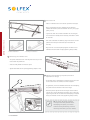
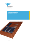
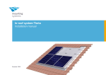
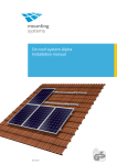
Lambda flat roof system
Installation manual
Artikelnummer: 810-0012
Contents
1
1.1
1.2
1.3
1.4
Introduction
Short description
Intended use
Standards and technical directives
About this manual
1
1
1
1
1
2
2.1
2.2
2.3
2.4
Safety
Basic safety instructions
Working on roofs
Warnings
Operator‘s responsibilities
2
2
2
2
3
3
3.1
3.2
3.3
3.4
Technical description
System overview
Scope of delivery
Technical specifications
Operating conditions
4
4
5
6
6
4
4.1
Planning of the module field
Dimensions
6
6
5
5.1
5.2
Important mounting information
Mounting aids and required tools
Additionally required materials
8
8
8
6
6.1
6.2
6.3
6.3.1
6.3.2
Installation
Preparation work
Installing the system
Installing the modules
Portrait installation
Landscape installation
Lambda Installation manual
Lambda — for universal use on flat roofs
Lambda-MA-ENG-1006
8
8
9
12
12
13
The Lambda flat roof system is a robust mounting system
for PV modules on flat roofs. It consists of aluminium
triangles, aluminium support rails and all necessary
accessories for attaching the modules to the rails and
connecting the components to one another. Further
components such as roof fixation kits or back plates are
also available. With Lambda, both portrait and landscape
module mounting are possible.
1.2 Intended use
The Lambda flat roof system is to be used for the
roof installation of PV modules only. Any other use is
considered improper.
The observance of the information in these assembly
instructions is a part of proper use. Mounting Systems
GmbH is not liable for damage that results from the
non-observance of assembly instructions, in particular
the safety information, or from the improper use of the
product.
1.4 About this manual
Subject
This manual details the installation and assembly of
the Lambda flat roof system. The illustrations in the
manual show the portrait mounting procedure for
framed modules. Should landscape mounting differ
from portrait mounting, this will be clearly emphasised.
Some additional components that are repeatedly
used are also indicated. No description is included for
materials for special substructures that may be required
to accommodate the constructional conditions of the
building in addition to standard materials. These
are always specially manufactured and documented
separately.
User group
This manual is intended for qualified personnel with a
basic knowledge of mechanics, hand tools and mechanical
skills.
1.3 Standards and technical directives
When planned correctly, Lambda fulfills the following
standards and technical directives:
• Eurocode 9 — DIN V ENV 1999-1-1: Design of aluminium
structures
• DIN 1055 — Actions on structures: Basis of design, safety
concept and design rules
Introduction
1
Lambda Installation manual
1. Introduction
1.1 Short description
2. Safety
2.1 Basic safety instructions
The following basic safety instructions and the warning
notes are an essential part of this manual and are of
fundamental importance for handling the product.
Lambda Installation manual
• Ensure that the product corresponds to the static
requirements on-site prior to every assembly and
installation.
• Ensure that the building corresponds to the increased
static requirements due to the PV unit, prior to every
mounting and installation.
• Observe occupational health and safety regulations of
the employer‘s liability insurance association.
• Use fall protection.
• Use protective equipment to guard against falling even
when carrying out short jobs.
• Do not carry materials on to the roof via ladders, but
rather use suitable lifting gear.
2.3 Warnings
The warning notes used in this manual identify safety
related information. They consist of:
• Warning symbol (pictograph)
• Indicator word to denote the danger level
• Information about type and source of the danger
• Wear a hard hat, protective gloves and safety shoes.
• A second person must be present during the entire
installation process, to give assistance in the event of
an accident.
• Information about possible consequences if the danger
is not observed
• Measures for avoiding the danger and for preventing
injuries or property damages
• A copy of this installation manual must be kept in the
direct vicinity of the unit.
2.2 Working on roofs
The heading of the warning notes identifies one of the
following danger levels:
When working on roofs, note the following instructions:
• Pay attention to accident prevention regulations for
working on roofs. If appropriate, use a barrier to protect
against falling parts.
DANGER
• In line with accident prevention regulations, work on
roofs should be carried out using safety harnesses for
individuals or safety scaffolding.
• Observe the relevant local safety regulations.
WARNING
• Before stepping on to the roof, check the load-bearing
capability of all parts which are under stress.
CAUTION
2
Safety
Denotes a major risk, failure to
observe which could lead to serious
injury or death.
Denotes a potentially dangerous
situation which may lead to
moderate to serious physical injury
and property damage.
Denotes a potential risk which may
lead to physical injury and property
damage.
2.4 Operator‘s responsibilities
The system operator has the following safety-relevant
responsibilities:
• Ensure that the installation of the system is only
performed by persons with manual skills and basic
knowledge of mechanics.
Lambda Installation manual
• Ensure that the assigned installation personnel can
evaluate the work assigned to them and can recognize
possible dangers.
• Ensure that the persons commissioned are familiar with
the system components.
• Ensure that the installation manual is accessible during
the assembly. The mounting instructions are an integral
part of this product.
• Ensure that the mounting instructions and in particular
the warnings have been read and understood by the
authorized installation personnel prior to assembly.
• Ensure that the permissible conditions of use (see
chapter 3.4, page 6) have been upheld. Mounting
Systems GmbH will not be held liable for damage which
results from a violation of these conditions.
• Ensure that the roof construction has the required loadbearing capacity, in particular in the vicinity of the force
transmission points.
• Ensure that the durability of the mounted connections
and the root atachments are guaranteed.
• Ensure that any necessary roof penetrations are
professionally sealed.
• Ensure that the appropriate lifting equipment is used for
the mounting process.
• Ensure that only Mounting Systems components are
used, also in case of replacement.
Otherwise the warranty claim is void.
Safety
3
3. Technical description
3.1 System overview
Components:
a Triangle (shown here with foot brackets)
b Triangle (shown here with ground rail)
All system components are described below. The design of
the individual system components may vary.
c X-Stone
d Base rail 13/58
e Splice 13/58 (not visible)
They are dependent on:
f Telescoping end piece 13/58
g Diagonal strut
Type of roof,
Type of module,
Number of modules and
The conditions on site.
h SolRec base plate (optional accessory)
i Module end clamp for landscape installation
j Module clamp
k Module end clamp for portrait installation
Lambda Installation manual
•
•
•
•
e
k
j
f
d
g
c
a
Portrait installation
i
b
h
Landscape installation
4
Technical description
All system parts and requisite
small parts which are required for
installation are included in the
delivery. The precise scope of supply
will depend on the size and
number of PV modules which
you specify when ordering.
No description is included for
materials for special substructures
that may be required in addition to
standard materials to accommodate
the constructional conditions of the
building.
a
b
c
d
e
f
g
h
i
j
k
l
m
n
o
p
q
r
s
t
Lambda Installation manual
3.2 Scope of delivery
a Triangle (shown here with foot brackets)
b Triangle (shown here with ground rail)
c X-Stone*
d Base rail 13/58
e Splice 13/58
f Telescoping end piece 13/58
g Diagonal strut
h SolRec base plate (optional accessory)
i Module end clamp* for landscape
installation, module frames between 32
and 56 mm
j Module clamp*
k Module end clamp* for portrait installation
for frame heights of 35, 43, 46 and 50 mm
l Module end clamp* for portrait
installations for frame heights of
24.5—51mm
mLaminate clamp*
n Laminate end clamp*
o Back plate (optional accessory)
p Concrete anchor (optional fixation material)
q Hanger bolt (optional fixation material)
r Bolt connection, consisting of Allen bolt M8
x 20, self-locking nut M8 and 2 washers
s Anti-slip device for modules, consisting of
nut M6 and Allen bolt M6 x 20
t Quickstone profile nut (not an individual
component, but pre-assembled on the
components marked *)
* with Quickstone
Technical description
5
3.3 Technical specifications
Support profile, base rails
Extruded aluminium (EN AW 6063 T66)
All other profiles
Aluminium (EN AW 6060 T6)
Accessories
Stainless steel (V2A)
Back plate
Aluminium (EN AW 5005)
SolRec base plate
PE
Lambda Installation manual
3.4 Operating conditions
Application range
Flat roof
Roof pitch
0 — 5°, greater pitch subject to prior verification
PV module
Framed, unframed
Roof construction
The suitability of the entire roof construction, in particular at the load transfer
points of the mounting system, must be examined for static, insulation, leak
tightness, and fire protection requirements prior to installation of the PV system.
Permissible roof load
Must be specifically checked for each project.
Attachment method
Must be specifically checked for each project.
Triangle and support rails
Up to 1,900 PA for a 2.5 m2 surface per triangle and a roof pitch up to 5°
Max. row length
12 m
Distance between the triangles
Depending on project planning, portrait installation up to approx. 1.5 m,
landscape installation up to approx. 1.8 m
4. Planning of the module field
4.1 Dimensions
Notice:
The material expansion of a 12 m-row
can be approx. 2 cm. Therefore,
a minimum distance of 10 cm between
the rows is recommended. Furthermore,
for large systems, it is wise to leave
more space at regular intervals as
maintenance paths.
i
In the following, the dimensions of the mounting system
will be given. The exact spacing between the triangles is
project-specific and must be individually defined in the
planning phase.
Width of the unit: Number of horizontal modules x
(module width + 19) + 31mm; maximum 12 m
j
b
e
f
h
g
Portrait installation
6
Technical description • Planning of the module field
a
k
b
c
a
d
Landscape installation
h Drill hole size in the foot brackets: 11 mm or 13 mm, depending on
a Depth of the frame unit: see table A below
selection
b Height of the frame unit: see table B below
i Ground rail, hole pattern for triangle models A and B:
c Pitch: 20°, 25°, 30°
see illustration I below
d Distance between the rows: according to project plan
e Distance to ground: at least 8 cm, depending on module positioning
j Distance between the base rails for portrait installation: Distance
of the clamp points as recommended by the module manufacturer
f Distance between the triangles: according to plan, portrait mounting
(usually marked by the drill holes in the module frame, approx. ½
up to approx. 1.5 m, landscape mounting up to approx. 1.8m
the module length).
g Distance between the foot brackets of the triangle: 955 mm / 1260
k Distance between the base rails for landscape installation: Distance
mm, depending on selected triangle type (model A/B)
of the outer edges of the rails = module width
Depth of the unit, including module
Pitch
Landscape installation
Portrait installation
module length x 0.94; at least 995 mm
20°
A
995 mm
25°
module length x 0.91; at least 995 mm
module length x 0.87; at least 995 mm
30°
Height of the frame unit, including module
B
Pitch
Landscape installation
Portrait installation
20°
534 mm
(module length x 0.34) + 80 mm; at least 534 mm
25°
615 mm
(module length x 0.42) + 80 mm; at least 615 mm
30°
692 mm
(module length x 0.50) + 80 mm; at least 692 mm
Hole pattern: Ground rail B
Hole pattern: Ground rail A
20
545
327
218
20
20
ø 6,1 mm
327
545
327
20
ø 6,1 mm
I
20
545
436
1.110
327
20
20
327
545
545
20
1.457
All dimensions in mm
Planning of the module field
7
Lambda Installation manual
i
5. Important mounting information
5.1 Mounting aids and required tools
5.2 Additionally required materials
You will need the following tools to install the
system:
• 6 mm Allen key
• Combination wrenches 13
• Folding rule / tape measure
• 9 mm metal drill bit
Depending on the system plan, the following additional
materials may be necessary:
• Suitable fixation material for roof
• Material for weighting as ballast, for example gravel,
concrete slabs or other
• Suitable protective mats to protect the roof surface.
Lambda Installation manual
Appropriate tools for the respective
roof mounting variations, e.g.:
• For riveting onto SolRec floor plates: 6.1 mm drill bit,
rivet gun
• For attachment with fix anchors into concrete: 12.5 mm
concrete drill bit, hammer
6. Installation
6.1 Preparation work
1 Preparing the fixation points
• Define and mark the fixation
points, and/or the planned
substructure according to plans,
and prepare for installing the
triangles.
DANGER
Potentially mortal danger
from falls and falling objects
• Protect yourself against
falling.
• Do not remain in the danger
zone.
• Wear a hard hat.
• After the assembly is
complete, ensure secure
positioning of the mounting
system and the modules.
20˚
25˚
2 Preparing the triangles
• Unfold the triangles and pre-mount
both of the support elements with
2 bolts each (self-locking nut M8, 2
washers and M8 x 20 Allen bolt) at
the desired angle
(tightening torque 8 Nm).
• Tighten all of the screw connections
on the triangle (tightening torque
8 Nm).
30˚
Material damage from improper mounting
CAUTION
3
Improperly fastened triangles can bend or collapse.
• Carry out all new bolted connections using the abovementioned materials (bolts, washers and nuts).
• After installation, ensure that all bolted connections are tight.
Mounting the anti-slip protection (only for portrait installation)
• Attach one bolt with M6 nut in each of the lower drill holes of the module
frame as an anti-slip protection, and tighten them by hand.
8
Important mounting information • Installation
6.2 Installing the system
1 Mounting the triangles
• While maintaining the planned
spacing, arrange the triangles so
they are parallel, and fix them
with the designated connecting
materials.
WARNING
Lambda Installation manual
Material damage due to inappropriate material selection
Inappropriate fixation material can cause the triangles to rip out, roof damage and leakage.
• Select appropriate fixation material according to the location, roof state, and system design.
Material damage from improper mounting
WARNING
Improperly fixed triangles can rip out and result in leaks.
• All attachments should be of professional quality.
• After mounting, ensure that the fixation is correct.
2 Fixing the X-stones
• Fix two X-stones per triangle
(see point 4.1 Dimensions) to the
support rail of the triangle at
the specified points. Take care to
observe the differing alignment
of the X-stones for portrait or
landscape installation
(see illustration on the right).
• Insert the Quickstone into the
profile channel so that the form
of the Quickstone fits perfectly
into the profile. The bolt may not
protrude beyond the lower edge of
the Quickstone.
• Fasten the Quickstone loosely with
2 bolt turns.
• Put the X-stone in the desired
position and line it up transversely
to the support rail.
• Tighten the bolt just enough
so that the X-stone does not slide
down. Do not tighten completely.
Portrait installation
Landscape installation
Material damage due to improper mounting
CAUTION
Improperly fastened X-stones may slip or rip out.
• All Quickstone connections must be mounted
according to instructions.
• After mounting, check that the bolted connections
are tight.
Installation
9
3 Install base rail
• Mount 2 horizontal base rail sections per row of triangles.
• Align and position the rails according to the selected
module dimensions (distance between the rails, see page 7
point j and k).
Lambda Installation manual
• Lay the rails with the smooth side down on the triangles
and fasten them loosely to the vertically-mounted x-stones
on the side.
• Take care to observe the differing alignment of the rails for
portrait or landscape installation (see illustration on
the left).
• Align the rails and subsequently tighten the vertical and
horizontal X-stone bolts finally (tightening torque 8 Nm).
Portrait installation
Landscape installation
4 Connecting the individual rails
• The splice should be slid in half-way from the side, on the
back side of the profile rail.
• Slide the next profile rail into the splice.
• Tighten both bolts of the splice (tightening torque 8 Nm).
5 Mounting the telescoping end piece (inclusion is
dependent on design)
• If intended, slide a telescoping end piece into the base rail
at the end of each rail section, but wait to tighten.
• If applicable, mount the flexible element of the telescoping
end piece onto the X-stone of the last triangle.
• After the precise adjustment to the length of the module
surface area, fix the telescoping end piece. This is done by,
tightening the bolt on the end of the telescoping end piece
facing the module surface area (tightening torque 8 Nm).
TIP: It is best not to pre-calculate
and adjust the exact position of the
telescoping end piece, but instead
to do the exact positioning and final
mounting while fixing the last module.
10 Installation
6 Attaching the diagonal struts
• Mount 2 diagonal struts per unit on the left and right
ends of the row.
• Loosely mount one end of the diagonal in the lowest
pre-drilled bore hole of the strut to the outside triangle
with a self-locking nut M8, 2 washers and an allen bolt.
• Fix the second end of the diagonal.
• Tighten both diagonal connections finally (tightening
torque 8 Nm).
• If necessary, shorten any protruding ends of the
diagonals (purely for appearance purposes).
Lambda Installation manual
• Point the strut diagonally to the next triangle in the row
and mark the exact position of that triangle’s uppermost bore hole on the diagonal.
• Drill a hole with diameter of 9 mm at the marked
location.
7
Attaching the back plate
(alternative to the diagonal struts)
• Hold the back plates against the
triangles from behind, and fix
them to the triangle supports with
two drill screws per triangle.
• Allow the back plates to overlap
by 5 cm.
Installation 11
6.3 Installing the modules
6.3.1 Portrait installation
CAUTION
1 Module positioning
Lambda Installation manual
• Place the modules on the rails so
that the slip-guard bolts are in the
lowest rail channel.
Material damage due to
improper mounting
Improperly fastened module
(end) clamps may rip out.
• All Quickstone connections
must be mounted according
to instructions.
• After installation, ensure that
the bolted connections are
tight.
2 Attaching the outer modules
• Insert the Quickstone of the module end clamps in the
top channel of the base rail (the bolt may not protrude
on the under side of the Quickstone) and fasten them
loosely.
• Before tightening, push the modules under the module
clamps and align them.
• Tighten the module end clamps (tightening torque 8
Nm).
3 Attaching the inner modules
• Insert the Quickstone of the module clamp into the top
rail channel of the base rail, slide them on to the previously mounted module and fasten loosely.
• Slide the second module onto the module clamp, align
it, and tighten the bolts (tightening torque 8 Nm).
i
12 Installation
When installing laminates, special
laminate end and/or laminate middle
clamps must be used. The installation
procedure is identical. Slide the laminate
between the rubber lips of the laminate
end clamp before tightening.
6.3.2 Landscape installation
1 Mounting the lower module end clamps for landscape
installation
• Fix two module end clamps per module to the lower base rail.
• The distance between the clamps should be based on
the optimal clamping points of the respective module
specified by the manufacturer (usually marked by the
drill holes in the module frame, approx. ¼ of the
module length from the right and the left).
2 Module positioning
• Place the module in landscape position onto the loosely
mounted lower module end clamps.
• Align the modules. It is not necessary to leave any space
between the individual modules.
• Adjust the height of the lower module end clamp by
means of the slotted hole so that the clamp lies directly
on the module. Finally tighten the clamps in this
position (tightening torque 8 Nm).
3 Mounting the upper module end clamps
Material damage due to improper
mounting
CAUTION
Improperly mounted module end
clamps may slip or rip out.
• All Quickstone connections must be
mounted according to instructions.
• After installation, ensure that the
bolted connections are tight.
• Make sure that the upper edge of the upper rail row is
flush with the modules and that the side rail channels
and the X-stones point upwards (see illustration page
10, point 3). If necessary, correct the positioning of the
base rail.
• Mount two end clamps per module to the upper base
rail, parallel to the positioning of the lower end clamps
and tighten finally (tightening torque 8 Nm).
Installation 13
Lambda Installation manual
• Insert the Quickstone of the end clamp into the side
channel of the rail and fasten loosely.
SOLFEX LTD
UNITS 3 - 5 CHARNLEY FOLD INDUSTRIAL ESTATE
BAMBER BRIDGE
PRESTON
LANCASHIRE
PR5 6PS
U.K.
TEL: 00 44 (0) 1772 312847
E-MAIL: [email protected]
WEBSITE: www.solfex.co.uk
Subject to technical alterations