1
International Journal of Engineering and Advanced Technology (IJEAT)
ISSN: 2249 – 8958, Volume-2, Issue-6, August 2013
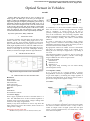
Optical Sensor in Vehicles
Aarathi
Abstract- When the vehicels turns in curve at night, it can
always appear “the blind spot” in the turn, for the lights are
unable to adjust the illumination angle. In order to enhance
safety driving at night, an adaptive front-lighting system (AFS) of
automobile controlled by STC12C5A60AD which is the core of
electric control unit is designed in this work. The AFS is based
on the steering wheel angle and speed changes to adjust light
axis angle to light up the road in the front, so the drivers' security
vision are improved. The work principles of the AFS[6] and
control model and hardware circuits are particularly described..
Keywords- optical sensor, Relay, LDR, LCD.
I.
INTRODUCTION
In vehicles switching the head light up and down when
another vehicles are coming during night need to do
manually. In this work switching ON/OFF of the head
light is made automatically by using light sensors such as
LDR (Light depended resistors).when the LDR senses the
light then it automatically switch the down light else it will
switch to head light .In this work LED((light emitting
diodes) are used for head light and down light indications.
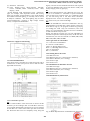
II. THE BLOCK DIAGRAM
AC/D
Regulat
Fil
C
or
te
Adap
(7805)
r
ter
Fig 2: Block diagram of power supply
DC
Outpu
t
A transformer is a device that transfers electrical energy
from one circuit to another through inductively coupled
coils or "windings. A varying current in the first or
"primary" winding creates a varying magnetic field in the
core of the transformer. This increasing magnetic field
induces a increasing electromotive force (EMF) or "voltage"
in the "secondary" winding. This effect is called mutual
induction.
If a load is connected to the secondary circuit, electric
energy or current will flow in the secondary winding of the
transformer and transfer energy from the primary circuit to
the load connected in the secondary circuit.
By appropriate selection of number of turns a transformer
thus allows an alternating voltage to be stepped up by
making Ns more than Np or stepped down , by making it
vice versa
The transformer produces 12 volts D.C. This is given to the
7805-voltage regulator to produce 5 volts D.C. The voltage
ranges of different 78xx series are given below.
VOLTAGE RANGE
LM7805C 5V
LM7812C 12V
LM7815C 15
For high power lamp switching one can connect Relay
(electromagnetic switch)
3.1.2 Regulator (78XX)
It is a 3 pin IC use as a voltage regulator it converts
unregulated DC current in to regulated dc current. Normally
we get fixed output by connecting the voltage regulator at
the output of the filtered DC .It can also be used in circuit to
get low DC voltage from a high DC voltage.
Fig. 1. Block diagram of this work is illustrated.
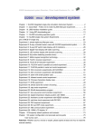
III. HARDWARE AND SOFTWARE PART
Hardware:
Power supply
LDR and driver Unit
Microcontroller
Light control unit
Focus light arrangement
Software:
Keil
Embedded C
Proload burner software
3.1.3 Relay:
3.1.1 Power Supply:
Power supply required for the micro controller 89C51 is 5
volts. The LM78XX series of three terminal regulators is
available with several fixed output voltages making them
useful in a wide range of applications.
Initially a step down transformer is used to step down the
input voltage to be given to the rectifier, which converts A.C
voltage to D.C voltage.
Manuscript received on August, 2013.
Aarathi-Assistant professor in B.K.I.T Bhalki (Karnataka), India.
AC
Power
Fig 3: Relay
A relay is an electrical switch that opens and closes under
the control of another electrical circuit. A relay is able to
control an output circuit of higher power than the input
circuit, it can be considered to be, in a broad sense, a form
of an electrical amplifier.
220
Optical Sensor in Vehicles
Relays are usually SPDT (single pole double through
switch) or DPDT (double pole double through switch) but
they can have many more sets of switch contacts, for
example relays with 4 sets of changeover contacts are
readily available.
Relays thus enables controlling an AC device through DC.
The relay's switch connections are usually labeled COM,
NC and NO:
COM = Common, always connect to this, it is the
moving part of the switch.
NC = Normally Closed, COM is connected to this when
the relay coil is off.
NO = Normally Open, COM is connected to this when
the relay coil is on.
Connect to COM and NO if you want the switched
circuit to be on when the relay coil is on.
Connect to COM and NC if you want the switched
circuit to be on when the relay coil is off.
Fig 4: Relay2
3.2 Light Dependent Resistor(LDR)
To detect the present of an object we have used LDR and a
source
of
light.
LDR
is
a
special type of resistance whose value depends on the
brightness of the light, which is falling on it. It has
resistance of about 1 mega ohm when in total darkness, but
a resistance of only about 5k ohms when brightness
illuminated. It responds to a large part of light spectrum.[2]
1) LDR use should be sensitive before using in the circuits
it should tested with the multimeter.
2) IC should not be heated much while soldering, too
much heat can destroy the IC while placing the IC pin
no 1 should be make sure at right hole.
3) Opposite polarity of the battery can destroy the IC so
check the polarity before switching on the circuits. one
should use diode in series with switch for safety
because diode allows current in only one direction.
4) Each component should be soldered neatly and clean
5) LDR should be adjusted that it should not get light
from streetlight
3.1.3.1 Basic operation of a relay:
An electric current through a conductor will produce a
magnetic field at right angles to the direction of electron
flow. If that conductor is wrapped into a coil shape, the
magnetic field produced will be oriented along the length of
the coil. The greater the current, the greater the strength of
the magnetic field, all other factors being equal.
Fig 5:Internal structure of Relay
If we place a magnetic object near such a coil for the
purpose of making that object move when we energize the
coil with electric current, we have what is called a solenoid.
The movable magnetic object is called an armature, and
most armatures can be moved with either direct current
(DC) or alternating current (AC) energizing the coil. The
polarity of the magnetic field is irrelevant for the purpose of
attracting an iron armature.
Fig 6: block diagram of Relay
A relay is an electrically operated switch. Current flowing
through the coil of the relay creates a magnetic field which
attracts a lever and changes the switch contacts. The coil
current can be on or off so relays have two switch positions
and most have double throw (changeover) switch contacts as
shown in the diagram.
Relays allow one circuit to switch a second circuit which
can be completely separate from the first. For example a low
voltage battery circuit can use a relay to switch a 230V AC
mains circuit. There is no electrical connection inside the
relay between the two circuits, the link is magnetic and
mechanical.
3.3 Light Emitting Diode (LED):
Light emitting diodes, or LEDs, differ from regular diodes
in that when a voltage is applied, they emit light. This light
can be red (most common), green, yellow, orange, blue (not
very common), or infrared. LEDs are used as indicators,
transmitters, etc. Most likely, a LED will never burn out like
a regular lamp will and requires many times less
current.LED are uses to obtain fixed voltage. The voltage
drop of LED is comparatively stable at just about 2v .[6]
3.4 LCD (Liquid Cristal Display)
A liquid crystal display (LCD) is a thin, flat display device
made up of any number of color or monochrome pixels
arrayed in front of a light source or reflector. Each pixel
consists of a column of liquid crystal molecules suspended
between two transparent electrodes, and two polarizing
filters, the axes of polarity of which are perpendicular to
each other. Without the liquid crystals between them, light
passing through one would be blocked by the other. The
liquid crystal twists the polarization of light entering one
filter to allow it to pass through the other.
3.4.1 Features:
(1) Interface
with
either
4-bit
or
8-bit
microprocessor.
(2) Display data RAM
(3) 80x8 bits (80 characters).
(4) Character generator ROM
(5). 160 different 5 x 7 dot-matrix character patterns.
(6). Display data RAM and character generator
RAM may be Accessed by the microprocessor.
221
International Journal of Engineering and Advanced Technology (IJEAT)
ISSN: 2249 – 8958, Volume-2, Issue-6, August 2013
(7) Numerous instructions
(8). Clear Display, Cursor Home, Display ON/OFF,
Cursor ON/OFF, Blink Character, Cursor Shift,
Display Shift.
Several different LCD technologies exists. “supertwist”
types, for example, offer Improved contrast and viewing
angle over the older “twisted nematic” types. Some modules
are available with back lighting, so that they can be viewed
in dimly-lit conditions. The back lighting may be either
“electro-luminescent”, requiring a high voltage inverter
circuit, or simple LED illumination.
Fig 7: block diagram of LCD
high (1) and wait for the minimum amount of time required
by the LCD datasheet (this varies from LCD to LCD), and
end by bringing it low (0) again.[2]
RS:
Line is the "Register Select" line. When RS is low (0), the
data is to be treated as a command or special instruction
(such as clear screen, position cursor, etc.). When RS is high
(1), the data being sent is text data which should be
displayed on the screen. For example, to display the letter
"T" on the screen you would set RS high.
RW:
Line is the "Read/Write" control line. When RW is low (0),
the information on the data bus is being written to the LCD.
When RW is high (1), the program is effectively querying
(or reading) the LCD. Only one instruction ("Get LCD
status") is a read command. All others are write commands,
so RW will almost always be low.
Finally, the data bus consists of 4 or 8 lines (depending on
the mode of operation selected by the user). In the case of an
8-bit data bus, the lines are referred to as DB0, DB1, DB2,
DB3, DB4, DB5, DB6, and DB7.
3.4.5 Logic status on control lines:
• E = 0 Access to LCD disabled
E=1 Access to LCD enabled
• R/W = 0 ,Writing data to LCD
R/W = 0 ,1 Reading data from LCD
• RS = 0, Instructions
RS = 0, 1 Character
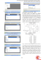
3.4.2 Power supply for lCD driving:
Fig 8: power supply of LCD
3.4.3 PIN DESCRIPTION:
Most LCDs with 1 controller has 14 Pins and LCDs with 2
controller has 16 Pins (two pins are extra in both for backlight LED connections).
3.4.6 Writing data to the LCD:
1) Set R/W bit to low
2) Set RS bit to logic 0 or 1 (instruction or character)
3) Set data to data lines (if it is writing)
4) Set E line to high
5) Set E line to low
3.4.7 Read data from data lines on LCD:
1) Set R/W bit to high
2) Set RS bit to logic 0 or 1 (instruction or character)
3) Set data to data lines (if it is writing)
4) Set E line to high
5) Set E line to low
3.4.8 Initialization by Instructions:
Fig 9: pin diagram of 1x16 lines LCD
Table1: pin description
3.4.4 Control lines of LCD:
EN:
Line is called "Enable." This control line is used to tell the
LCD that you are sending it data. To send data to the LCD,
your program should make sure this line is low (0) and then
set the other two control lines and/or put data on the data
bus. When the other lines are completely ready, bring EN
222
Fig 10: Block Representation of initialization by instruction
Optical Sensor in Vehicles
3.4.9 LCD Display
A Liquid crystal display (LCD) is a low cost, low
power device capable of displaying text and images.
The LCD controller provides a relatively simple
interface between a processor and an LCD. LCDs can
be added quite easily to an application and use as few as
three digital output pins for control.
Figure8.1: Schematic diagram of an
LCD
There are different types of LCDs such as reflective LCD,
absorption LCD, dot matrix LCD. Each type of LCD is able
to display multiple characters. In addition, each character
may be displayed in normal or inverted fashion. The LCD
may permit a character to be blinking or may permit display
of a cursor indicating the” current” character. Such
functionality would be difficult to be implemented using
software.
Thus, an LCD controller is used to provide a simple
interface to an LCD, perhaps eight data inputs and one
enable input. This byte may be a control word, which can be
an instruction or data word The most common connector
used for the 44780 based LCDs is 14 pins in a row, with pin
centers 0.100" apart
3.5 Buzzer
A buzzer or beeper is a signaling device, usually electronic,
typically used in automobiles, household appliances such as
a microwave oven, or game shows.
a ceramic-based piezoelectric sounder like a Son alert which
makes a high-pitched tone. Usually these were hooked up to
"driver" circuits which varied the pitch of the sound or
pulsed the sound on and off.
Go to Project – Select Device for Target „Target1‟ Select
8052(all variants) and click OK
Now we need to check the oscillator frequency:
Go to project – Optionss for Target „Target1‟
IV. SOFTWARE EXPLANATION
4.1 Keil Software
Installing the Keil software on a Windows PC
Insert the CD-ROM in your computer‟s CD drive
On most computers, the CD will “auto run”, and you
will see the Keil installation menu. If the menu does not
appear, manually double click on the Setup icon, in the
root directory: you will then see the Keil menu.
On the Keil menu, please select “Install Evaluation
Software”. (You will not require a license number to
install this software).
Follow the installation instructions as they appear.
Loading the Projects
The example projects for this book are NOT loaded
automatically when you install the Keil compiler.
These files are stored on the CD in a directory “/Pont”. The
files are arranged by chapter: for example, the work
discussed in Chapter 3 is in the directory “/Pont/Ch03_00Hello”.
Rather than using this work on the CD (where changes
cannot be saved), please copy the files from CD onto an
appropriate directory on your hard disk.
Note: you will need to change the file properties after
copying: file transferred from the CD will be „read only‟.
Make sure that the oscillator frequency is 12MHz.
4.2 Configuring the Simulator
Open the Keil Vision2[4]
Go to Project – Open Project and browse for Hello in
Ch03_00 in Pont and open it.
First start a debug session
223
International Journal of Engineering and Advanced Technology (IJEAT)
ISSN: 2249 – 8958, Volume-2, Issue-6, August 2013
The flashing LED we will view will be connected to Port 1.
We therefore want to observe the activity on this port
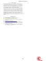
4.2 Description of microcontroller 89S52:
The AT89S52 is a low-power, high-performance CMOS 8bit micro controller with 8Kbytes of in-system
programmable Flash memory. The device is manufactured
Using Atmel‟s high-density nonvolatile memory technology
and is compatible with the industry-standard 80C51 micro
controller. The on-chip Flash allows the program memory to
be reprogrammed in-system or by a conventional
nonvolatile memory programmer. By combining a versatile
8-bit CPU with in-system programmable flash one
monolithic chip; the Atmel AT89S52 is a powerful micro
controller, which provides a highly flexible and costeffective solution to many embedded control applications.
To ensure that the port activity is visible, we need to start
the „periodic window update‟ flag
Fig 11: architecture and pin configuration of microcontroller
Go to Debug - Go
The AT89S52 provides the following standard features: 8K
bytes of Flash, 256 bytes of RAM, 32 I/O lines, Watchdog
timer, two data pointers, three 16-bit timer/counters, full
duplex serial port, on-chip oscillator, and clock circuitry. In
addition, the AT89S52 is designed with static logic for
pertain down to zero frequency and supports two software
selectable power saving modes. The Idle Mode stops the
CPU while allowing the RAM timer/counters, serial port,
and interrupt system to continue functioning. The Powerdown mode saves the RAM contents but freezes the
oscillator, disabling all other chip functions until the next
interrupt
224
Optical Sensor in Vehicles
V. CONCLUSION
The developed system was put under a series of tests for
ascertaining its performance as a protective device and very
satisfactory results were obtained. When the load current
exceeds 10A, the load was turned off. The upper and lower
level responses of this device were also found[5]
to be sufficiently quick, so that the safety of the equipment
protection by the device under any undesired transient
condition of the main supply was ensured. This device had a
very high sensitivity. It was also simple in design, reliable in
operation and cost competitive with any other product
available in the market. From the above analysis, it is
concluded that this device can easily protect electrical
appliances against fluctuation of line voltages and over load
current
REFERENCES
[1]
[2]
[3]
[4]
[5]
[6]
[7]
[8]
Hanwei Electronics Co., LTD, “MQ-5”
Theodore S Rappa port, “Wireless Communications”.
Karnataka State Fire and Emergency Services
Keil Embedded Development Tools for ARM, “User Manual for
LPC2129.
Wikipedia for list of light sensor
www.al-lighting.com/lighting/headlamps/afs
R. Cucchiara and M. Piccardi, “Vehicle detection under day and
night illumination,”International ICSC Symposium on Intelligent
Industrial Automation,1999.
N. Matthews, P. An, D. Charnley, and C. Harris, “Vehicle detection
and recognition in greyscale imagery,” Control Engineering
Practice, vol. 4, pp. 473–479, 1996
225