1
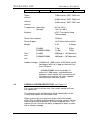
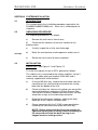
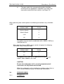
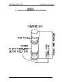
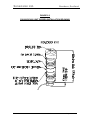
Sonavision Ltd.
Aberdeen, Scotland
OPERATION AND
INSTALLATION MANUAL
DETAILS OF THE EQUIPMENT
PART NUMBER:
2360-10-0001
DESCRIPTION:
SV3000,SV4000 & SV6000 OPERATING
AND INSTALLATION MANUAL
APPROVALS
ORIGINATOR:
ENGINEER:
PRODUCTION:
ISS
DATE
R.J HARDIE
R.J HARDIE
DESCRIPTION
BY
0
DRAFT FOR APPROVAL
1
RELEASE FOR PRODUCTION
2
30/03/10
UPGRADE TO NEW DOCUMENTATION
CHK
RH
3
Issue 2
2360-31-0018
Page 1 of 23
Sonavision Ltd.
Aberdeen, Scotland
4
5
The latest issue of this document is held in electronic form.
This is available from our website www.sonavision.co.uk
COPYRIGHT © SONAVISION LIMITED
AUGUST 2008
The copyright in this document is the property of Sonavision Limited. The document
is supplied by Sonavision Limited on the express terms that it may not be copied,
used, or disclosed to others except as authorised in writing by Sonavision Limited.
Sonavision Limited reserves the right to change, modify and update designs and
specifications as part of their ongoing product development programme.
TECHNICAL SUPPORT
Address
Sonavision Limited
Unit 12 Energy Development
Centre
Aberdeen Science and Energy
Park
Bridge of Don
Aberdeen
AB23 8GD
Scotland
Telephone
+44 (0)1224 707737
Fax
+44 (0)1224 827290
Email
[email protected]
Website
www.sonavision.co.uk
Issue 2
2360-31-0018
Page 2 of 23
Sonavision Ltd.
Aberdeen, Scotland
MAINTENANCE AND WARRANTY POLICY
Sonavision Limited warrants that its products are free from defects at the
time of delivery and subject to the conditions listed below, undertakes to
repair, or at its option replace, any product found to be defective in material
or workmanship within one year after delivery, whichever is less, to the
original purchaser by Sonavision Limited or its authorised representative.
CONDITIONS
1. Sonavision Limited must be immediately notified of any suspected defect
and if advised by Sonavision Limited, the equipment subject to defect
shall be returned to Sonavision Limited, freight prepaid.
2. This warranty does not cover defects which are caused as a result of
improper usage, repair, maintenance, alteration or installation unless
such activities have been undertaken by Sonavision Limited or its
authorised representative.
3. On completion of any warranty work, Sonavision Limited will return the
equipment, freight prepaid.
4. Sonavision Limited retains the sole right to accept or reject any warranty
claim.
SAFETY AND ENVIRONMENTAL STATEMENT
1. Lethal voltages are exposed within the control unit when the top cover is
removed. The unit should always be disconnected from the mains
supply before removing or operating any internal components.
2. The unit should be earthed at all times.
3. The unit contains electrostatically sensitive devices (ESSD). Appropriate
static protection should be used when handling subassemblies.
RELATED DOCUMENTS
Document Number
Issue 2
Document Title
2360-31-0018
Page 3 of 23
Sonavision Ltd.
Aberdeen, Scotland
PREFACE
This manual contains user information for the SONAVISION SV4000, SV6000
and SV3000 Scanning Sonars, and is divided into three sections:
Section 1
An Introduction to the SONAVISION 2360, 2366 and
2367 and tunable variants
Section 2
System Installation Procedures
Section 3
Operating Instructions
Appendix A
only
Transducer Installation Procedure for SV4000 units
Note: Transducer installation by clients must only be
carried out with permission from SonaVision to avoid
invalidating the warranty.
Relevant figures are provided at the rear of each section.
Should you have any comments about this manual, or the product,
SonaVision are most interested in hearing from you as part of our product
improvement scheme.
Issue 2
2360-31-0018
Page 4 of 23
Sonavision Ltd.
Aberdeen, Scotland
1.1.1
1.1.2 CONTENTS
SECTION 1
INTRODUCTION AND GENERAL DESCRIPTION
1.1
1.1.1
1.1.2
INTRODUCTION
Overview
Major Technical Features
1.2
SPECIFICATION
1.3
OVERALL SYSTEM DESCRIPTION
Figure 1.1
Figure 1.2
System Units Layout
System Diagram
SECTION 2
SYSTEM INSTALLATION
2.1
INTRODUCTION
2.2
2.2.1
PACKAGING
Unpacking Procedure
2.3
INSTALLATION
2.4
2.4.1
2.4.2
2.4.3
2.4.4
PRE DIVE CHECK
2360 Unit
Seal Recharging Procedure
2366/2367 Units
Seal Life
Figure 2.1
Figure 2.2
Figure 2.3
Figure 2.4
Figure 2.5
Figure 2.6
Figure 2.7
Figure 2.8
2360 Unit Subsea Installation Drawing
2366/2367 Unit Subsea Installation Drawing
Transducer Orientation 2360 Unit
Transducer Orientation 2366/2367 Unit
Subsea Unit To Host Vehicle Connections
Grease Indicator Position
2360 Dual Unit Subsea Installation Drawing
2366/2367 Dual Unit Subsea Installation Drawing
APPENDIX A
TRANSDUCER INSTALLATION PROCEDURE
Figure A-1
Subsea Unit Sub-assemblies
Issue 2
2360-31-0018
Page 5 of 23
Sonavision Ltd.
Aberdeen, Scotland
SECTION 1 INTRODUCTION AND GENERAL DESCRIPTION
1.1
INTRODUCTION
1.1.1
Overview
Any of the SV4000, SV6000 or the SV3000 (see Figure 1.1)
underwater units are a single assembly which can be mounted
upright, inverted or horizontally on the vehicle.
The surface control unit and subsea unit communicate with each
other via a special duplex serial link, with operational data
supplied by the control unit with sonar data and heading
information supplied from the subsea unit.
The SV4000 unit is capable of operating up to 1,500 metres of
RG108 or equivalent. No adjustments to the system are
required for different lengths of cable.
For the SV6000/SV3000 units using cable lengths in excess of
1,500 metres communications between surface control unit and
subsea unit will require transmission via client supplied
communication interface system.
For the subsea units to be driven from the 2055 surface units or
2054 PC Interface Boxes, note that a special version of software
is fitted to the subsea processor board, it’s number is 8033-XX1000.
The subsea units should be powered directly from the vehicle
with only two wires of screen twisted pair to connect the sonar
communications to topside. A test cable can be ordered which
would allow testing of sonar head directly from control unit or
interface box.
For subsea units to be driven from 2060B, 2100 surface units or
2062, 2102 interface boxes. (Note: These units now replace all
the above units as standard topsides). The software version for
operation with these units can be either 8015-XX-1100 or 8033XX-1000 but will require adjustments to the surface software
selections. Refer to 2060-SOFT manual.
Note that for SV4000, SV6000 and SV3000 subsea units for the
purpose of this manual are shown in all diagrams as fitted with a
standard 500kHz array. It is possible for any of the above units
to have an array of different operating frequencies fitted or to
have a dual head or tunable version in use. These will cause
the units to be visually different from the manual drawings and
will affect the dimensions as seen in Figures 2.7 and 2.8.
1.1.2
Major Technical Features
The following technologies are used within the units:
-
Issue 2
Surface Mount Technology.
2360-31-0018
Page 6 of 23
Sonavision Ltd.
Aberdeen, Scotland
-
Solid State Digitally Controlled Receiver.
-
Composite Transducer Arrays.
For subsea units to be driven from the older 2050 and 2050C control
units power can be supplied by the vehicle or directly from the surface
unit via the same screened twisted pair for sonar communications link,
giving two wire operation. This method of operation is called FSK.
For subsea units being powered directly from the vehicle only two wires
connect the surface unit via a screen twisted pair for sonar
communication only giving two-wire operation. This method of
operation is called RS422. The software version fitted to the subsea
processor board is 8015-XX-1100.
1.2
SPECIFICATION
PARAMETER
500 kHz ARRAY
1MHz PROFILE
ARRAY
200kHz ARRAY
Horz.
Vert.
2.1°
27.0º
1.7°
1.7°
3.0°
20.0°
MDS
<74dB
<74dB
<74dB
Source Level
210dB/µPa
re/1m
210dB/µPa re/1m
210dB/reµPa
@/1m
Pulse Length
100µsec
100µsec
100µsec
Bandwidth
10kHz
10kHz
10kHz
Beamwidth
325kHz-675kHz
Tunable Array
250kHz-500kHz
Tunable Array
PARAMETER
At 325kHz
At 675kHz
At 250kHz
At 500kHz
Beamwidth:Horz.
Vert.
3.3º
41º
1.6º
19.5º
2.6º
30º
1.3º
15º
MDS
80max
83max
80dB
82dB
Source Level
210Typ
212Typ
212
Pulse Length
100µsec
100µsec
210
(min. 207)
100µsec
100µsec
Bandwidth
Issue 2
2360-31-0018
Page 7 of 23
Sonavision Ltd.
Aberdeen, Scotland
Depth:
variants
1,000 metres UNIT 2360 and
6,000 metres UNIT 2366 and
variants
3,000 metres UNIT 2367 and
variants
Temperature: Operating:
Storage:
0°C to +40°C
-20°C to +60°C
Material:
uPVC Transducer Head
Titanium body
Power Consumption:
15 Watts
Power Supply:
18-32 Volts (from vehicle)
Weight:
In Air
In Water
SV4000
SV6000/SV3000
7.7kg
12.4kg
3.5kg
7.5kg
SV4000
390(long) x 107(diameter)
SV6000/SV3000
465(long) x 107(diameter)
Size:
mm
mm
Umbilical Length: SV4000 unit 1,500 metres of RG108 or similar
twisted pair with a d.c. loop resistance of less
than 220 ohms.
SV6000/SV3000 unit using lengths in
excess of 1,500 metres, communications
between surface control unit and subsea unit
will require transmission via client supplied
communication interface system.
1.3
OVERALL SYSTEM DESCRIPTION, see Figure 1.2
The system consists of two units, the surface control unit and
the subsea unit.
The interconnection will depend on which combination of the
surface and subsea units are to be used.
Older systems will have provision to be used in two modes
either FSK or RS422 operation while the newer systems will not
have the provision to operate FSK from the topside units. The
subsea unit will still have the ability to operate on older systems
with a software change.
Issue 2
2360-31-0018
Page 8 of 23
Sonavision Ltd.
Aberdeen, Scotland
The surface unit sends telemetry information to the subsea unit
including range, gain, sector centre, motor speed, transmit
command, etc. The subsea unit responds with the received
sonar data and head orientation.
The subsea unit uses the information supplied from the surface
to control the operation of the motor, the transmit pulse and the
receiver gain.
The surface control unit processes the received sonar data,
displays it and then sends any status changes to the subsea unit
along with the next transmit command.
The user can initiate status changes via the controls on either
the front panel, the remote unit or by utilising the software
controlled menu system.
FIGURE 1.1
SV4000/SV6000/SV3000 SUBSEA UNITS
SV6000/SV3000
Issue 2
SV4000
2360-31-0018
Page 9 of 23
Sonavision Ltd.
2
Aberdeen, Scotland
FIGURE 1.2
SYSTEM DIAGRAM
Issue 2
2360-31-0018
Page 10 of 23
Sonavision Ltd.
Aberdeen, Scotland
SECTION 2 SYSTEM INSTALLATION
2.1
INTRODUCTION
This section details the installation procedure required for the
SV4000/SV6000/SV3000 units. Each unit is checked prior to
shipment.
2.2
UNPACKING PROCEDURE
The unpacking procedure is as follows:
a)
Remove the unit from its transit case.
b)
Check that the contents of the case conform to the
packing notes.
c)
Visually inspect the unit for transit damage.
d)
Notify the manufacturer of discrepancies and/or transit
e)
Retain the transit case for future shipment.
damage.
2.3
INSTALLATION
Subsea Unit - See Figure 2.1 and Figure 2.2
To install the subsea unit on an ROV, proceed as follows:
The subsea unit is connected to the vehicle umbilical, via the 2
metre subsea cable whip, part number 2238-2001 and is
normally supplied with no termination.
a)
Using an M5 Allan key, remove the cover plate from the
connector on the subsea whip and remove the sealing
boot from the bottom of the unit.
b)
Check and clean the subsea unit mating area around the
connector and clean and grease (Silicon Grease, Dow
Corning MS4 Silicone Compound or equivalent) the face
and piston o-rings on the cable whip connector.
c)
Bring the two connectors together, aligning the whip
dowel pin to the subsea unit dowel hole.
d)
Secure connector with the 3 X M5 screws provided on
removing the connector cover plate with Allan key.
NOTE: Please ensure that the three cap screws are
tightened equally thus ensuring correct bottoming of
the connector and that the back up ring is not
trapped across a mating surface.
Issue 2
2360-31-0018
Page 11 of 23
Sonavision Ltd.
e)
Aberdeen, Scotland
The open end of the interconnecting cable should be
terminated to an appropriate underwater connector and
connection made to the host vehicle, see Figure 2.5.
When operating from vehicle power the following connections only should be
made:
SIGNAL NAME
PIN No
RS422+/RS485+
2
RS422-/RS485-
5
+24V
3
0V
4
This option may be used in combination with a 2050C, 2055 or a
2060 control unit.
When operating from a 2050 surface control unit power the following
connections only should be made:
SIGNAL NAME
PIN No
CC+
6
CC-
1
This option is only valid with a 2050 control unit but not with
2050C, 2055, 2060B or the 2100.
CAUTION
Ensure the underwater unit is securely mounted and all
connectors are fully home and secured.
When the underwater unit is installed on a platform other than an
ROV, contact factory for details of necessary connections.
2.4
PRE-DIVE CHECK
2.4.1
SV4000 Unit
Issue 2
2360-31-0018
Page 12 of 23
Sonavision Ltd.
Aberdeen, Scotland
The subsea unit should be washed with fresh water after each
recovery to remove seawater, mud, silt and any other
contaminants.
Also check pre-charged seal indicator pin, see Figure 2.6, has
not fallen to below 5mm from the surface of the end cap. If it
has, follow charging procedure, Section 2.4.2.
The subsea unit contains a high performance rotating seal
mechanism, incorporating an active compensation device. This
seal is pre-charged with lubricant and for this reason it is
important that the components are not removed or loosened in
any way, as any such action would result in a de-pressurisation
of the compensator and risk a possible premature failure of
seals flooding the sonar.
2.4.2
SEAL RE-CHARGING PROCEDURE - see Figure 2.6
The procedure for re-charging the seal assembly is as follows:
a)
Remove the filter port plug (diametrically opposite the
indicator) to expose the grease nipple.
b)
Connect a grease gun, charged with SHELL ALVANIAN
MULTI PURPOSE GREASE, to the grease nipple.
c)
Begin to charge the unit from the grease gun, observing
the position of the indicator.
d)
Stop filling when the indicator is 1-2mm below the surface
of the end cap.
e)
Remove the grease gun.
f)
Pack the filler port with grease and replace the plug.
Note: If the grease cover is not tightened, there is a risk of
flooding to the sonar.
2.4.3
SV6000/SV3000 UNIT
The subsea unit should be washed with fresh water after each
recovery to remove seawater, mud, silt and any other
contaminants.
Inspect the indicator pin in the centre of the transducer cover
plate (see Figure 2.2). This pin should be near flush with the
cover, but must not be more than 3mm below the surface.
If the indicator pin is below the above level, the unit must be
returned to SonaVision Limited or an approved service centre for
maintenance. (See manufacturer for details).
Issue 2
2360-31-0018
Page 13 of 23
Sonavision Ltd.
2.4.4
Aberdeen, Scotland
SEAL LIFE
The shaft and seal sleeve are designed for a service free
maintenance period of 2,000 hours in normal operating
conditions.
SonaVision recommend component replacement at 2,000 hour
intervals, or every two years (whichever is sooner) by returning
the unit to our Service Department or an approved service
centre for inspection and refurbishment.
Issue 2
2360-31-0018
Page 14 of 23
Sonavision Ltd.
Aberdeen, Scotland
FIGURE 2.1
3
Issue 2
SV4000 UNIT SUBSEA INSTALLATION DRAWING
2360-31-0018
Page 15 of 23
Sonavision Ltd.
Aberdeen, Scotland
FIGURE 2.2
SV6000/SV3000 UNIT SUBSEA INSTALLATION DRAWING
Issue 2
2360-31-0018
Page 16 of 23
Sonavision Ltd.
Aberdeen, Scotland
FIGURE 2.3
TRANSDUCER ORIENTATION SV4000 UNIT
Issue 2
2360-31-0018
Page 17 of 23
Sonavision Ltd.
Aberdeen, Scotland
FIGURE 2.4
TRANSDUCER ORIENTATION SV6000/SV3000 UNIT
Issue 2
2360-31-0018
Page 18 of 23
Sonavision Ltd.
Aberdeen, Scotland
FIGURE 2.5
SUBSEA TO HOST VEHICLE CONNECTIONS
Issue 2
2360-31-0018
Page 19 of 23
Sonavision Ltd.
Aberdeen, Scotland
FIGURE 2.6
GREASE INDICATOR POSITION
Issue 2
2360-31-0018
Page 20 of 23
Sonavision Ltd.
Aberdeen, Scotland
APPENDIX A
TRANSDUCER HEAD INSTALLATION PROCEDURE
This procedure describes the actions necessary to install an optional
frequency transducer head on the SV4000 Sonar. The kit consists of the
transducer head and a pre-amplifier.
As the SV6000 and SV3000 are oil filled they must be returned to SonaVision
or an approved service centre for a transducer change.
Before commencing, ensure all power is removed from the system.
The procedure is divided into two sections.
Section One concerns
fitting the transducer head onto the transducer unit.
Section Two
describes how to change the configuration of the surface control unit
tog generate the required transmission frequency.
A-1.0
CHANGE THE TRANSDUCER HEAD - see Figure 1
a)
Remove the six M4 cap screws securing the cover plate, and lift
off the cover plate.
b)
Remove the two M3 cap screws securing the pre-amplifier and
gently prise out the board. Store the board in a package
providing electrostatic protection.
c)
Remove the two M2.5 counter-sunk screws securing the slipring
connector bracket and lift the bracket and connector clear.
d)
Remove the four M4 cap screws securing the transducer head
to the flange and lift the head clear.
e)
Clean, grease with Dow Corning MS4 Silicone Compound (or
equivalent) and replace the o-ring and replace in the flange.
f)
Place the new transducer head on the flange, ensuring that the
dowel pin locates in the keyring hole in the underside of the
head.
Issue 2
2360-31-0018
Page 21 of 23
Sonavision Ltd.
Aberdeen, Scotland
g)
Secure the transducer head by fitting and tightening the four M4
cap screws.
h)
Position the slipring connectors’ bracket in the head cavity and
secure with the two M2.5 counter-sunk screws.
NOTE: Take care not to pinch the conductors when fixing the
connector bracket. Route the cables in a gentle loop around the
mounting pillar.
I)
Gently fit the new pre-amplifier onto the leads mating it to both
the slipring and array ensuring that that array wires (coloured)
are fitted to PL2 and the slipring wires (white) are fitted to PL1.
Secure the board with the two M3 cap screws.
j)
Clean, grease with non-silicon based grease and replace the oring and replace in the cover plate.
k)
Position the cover plate on the transducer head, align the fixing
holes, fit and tighten the six M4 cap screws to secure the cover
plate.
FIGURE A-1
SUBSEA UNIT SUB-ASSEMBLIES
Issue 2
2360-31-0018
Page 22 of 23
Sonavision Ltd.
Aberdeen, Scotland
END OF DOCUMENT
Issue 2
2360-31-0018
Page 23 of 23