1
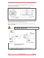
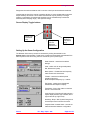
SeaKing Sidescan
Operators Manual
The electronic version of this document is the controlled copy.
Therefore all printed versions of this document are uncontrolled.
Supplied by
Issue 3
TIL – Eng – Spec – 041
SeaKing Sidescan OM
COPYRIGHT
© Tritech International Ltd
The copyright in this document is the property of Tritech International
Limited. The document is supplied by Tritech International Limited on
the understanding that it may not be copied, used, or disclosed to
others except as authorised in writing by Tritech International Limited.
Tritech International Limited reserved the right to change, modify and
update designs and specifications as part of their ongoing product
development programme.
F063.1
Tritech International Ltd
SeaKing Sidescan OM
TABLE OF CONTENTS
Warranty Statement
5
Safety Statements
6
Technical Support
6
SEAKING SIDESCAN SONARS INTRODUCTION
7
Subsea sensor Electrical Installation
8
ST Head Subsea Interconnect Cabling
8
SEAKING Communication Configuration
10
Ground Fault Monitoring Equipment
10
Mechanical Installation
10
USING THE ST SONAR
11
SEAKING sidescan Sonar Operating Notes
12
SCREEN DISPLAY
12
Main Sidescan Sonar Controls........................................................................................12
Setting Up the Sonar Configuration.................................................................................13
Dynamic Range
14
Sonar Slope Control
14
MAINTENANCE OF THE SEAKING SUBSEA UNITS
15
TROUBLE SHOOTING
15
Symptoms:......................................................................................................................15
SEAKING SCU Head Status Codes................................................................................15
Ground Fault Monitoring Equipment ...............................................................................15
SPECIFICATION
Issue 3
16
TIL – Eng – Spec – 041
Page 4 of 16
Tritech International Ltd
SeaKing Sidescan OM
Warranty Statement
Tritech International Limited herein after referred to as TIL
TIL warrants that at the time of shipment all products shall be free from defects in material and workmanship and suitable
for the purpose specified in the product literature.
The unit/system warranty commences immediately from the date of customer acceptance and runs for a period of 365
days. Customer acceptance will always be deemed to have occurred within 72 hours of delivery.
Note: Any customer acceptance testing (if applicable) must be performed at either TIL premises or at one of their
approved distributors unless mutually agreed in writing prior to despatch.
Conditions:
These include, but are not limited to, the following:
1
The warranty is only deemed to be valid if the equipment was sold through TIL or one of its approved distributors.
2
The equipment must have been installed and commissioned in strict accordance with approved technical
standards and specifications and for the purpose that the system was designed.
3
The warranty is not transferable, except or as applies to Purchaser first then to client.
4
TIL must be notified immediately (in writing) of any suspected defect and if advised by TIL, the equipment subject
to the defect shall be returned by the customer to TIL, via a suitable mode of transportation and shall be freight
paid.
5
The warranty does not apply to defects that have been caused by failure to follow the recommended installation or
maintenance procedures. Or defects resulting from normal wear & tear, incorrect operation, fire, water ingress,
lightning damage or fluctuations in vehicles supply voltages, or from any other circumstances that may arise after
delivery that is outwith the control of TIL.
(Note: The warranty does not apply in the event where a defect has been caused by isolation incompatibilities.)
6
The warranty does not cover the transportation of personnel and per diem allowances relating to any repair or
replacement.
7
The warranty does not cover any direct, indirect, punitive, special consequential damages or any damages
whatsoever arising out of or connected with misuse of this product.
8
Any equipment or parts returned under warranty provisions will be returned to the customer freight prepaid by TIL
9
The warranty shall become invalid if the customer attempts to repair or modify the equipment without appropriate
written authority being first received from TIL.
10
TIL retains the sole right to accept or reject any warranty claim.
11
Each product is carefully examined and checked before it is shipped. It should therefore be visually and
operationally checked as soon as it is received. If it is damaged in anyway, a claim should be filed with the courier
and TIL notified of the damage.
Note: TIL reserve the right to change specifications at any time without notice and without any obligation to
incorporate new features in instruments previously sold.
Note: If the instrument is not covered by warranty, or if it is determined that the fault is caused by misuse, repair
will be billed to the customer, and an estimate submitted for customer approval before the commencement of
repairs.
F167.1
Issue 3
TIL – Eng – Spec – 041
Page 5 of 16
Tritech International Ltd
SeaKing Sidescan OM
Safety Statements
Throughout the manual certain safety or operational related comments and
requirements will be highlighted to the operator by indications identified by the
adjacent symbol and text.
Caution!
Technical Support
Contact your local agent or Tritech International Ltd
Mail
Tritech International Ltd.
Peregrine Road,
Westhill Business Park,
Westhill, Aberdeen,
AB32 6JL, UK
Telephone
++44 (0)1224 744111
Fax
++44 (0)1224 741771
Email
[email protected]
Web
www.tritech.co.uk
An out-of-hours emergency number is available by
calling the above telephone number
If you have cause to use our Technical Support service, please ensure that you have the
following details at hand prior to calling:
•
•
•
System Serial Number (if applicable)
Fault Description
Any remedial action implemented
Due to the expansion of equipment capabilities and the fact that new sub-modules are
continually being introduced, this manual cannot detail every aspect of the operation.
Issue 3
TIL – Eng – Spec – 041
Page 6 of 16
Tritech International Ltd
SeaKing Sidescan OM
SEAKING SIDESCAN SONARS INTRODUCTION
The ST SEAKING range of sidescan sonars includes both towfish and ROV versions and are
available with two standard frequencies, 325 and 675kHz. Other frequency options are
available and Tritech should be contacted for more details of these.
The transducer arrays are available in different configurations for various beam shapes.
The electronics for the towfish system are contained within the fish, while the ROV systems
has two separate transducers which are connected with interconnect leads to a dual channel
electronics pod.
A waterblock connector is fastened to the fish or electronics pod, and provides a 4000metre
rated pressure bulkhead. The 6-way underwater connector is secured to the waterblock fitted
to the body tube using four cap screws, this connects to the pins on the PSU/COMMS PCB.
An O-ring seals the connector to the waterblock.
The SEAKING sidescan systems have the facility for the Gain and Time Variable Gain (TVG)
slope to be set-up from the SEAKING Surface Control Unit, to specific user requirements.
ROV Sidescan Installation
25º
Port
Stbd
Front view of vehicle
Side view of vehicle
Notes
1) Electronics pod can be mounted anwhere.
2) Transducers can be connector forward or connector aft.
3) Transducers should be close to pitch centre of vehicle
The SEAKING sidescan transducers are each supplied with their own colour coded
waterblock connector and interconnect cable to the electronics pod. The electronics pod has
its own water block connector and is supplied with a cable tail to connect to the customers
system.
Depending on the specification of the system, this cable will either need to be terminated to a
suitable connector appropriate to the operators equipment, or may be supplied with a cable
assembly to one or more additional connectors.
The waterblock is fastened to the electronics pod, and provides a 4000metre rated pressure
bulkhead. This will protect the electronics from water ingress in case the connector is
damaged or not fitted correctly. The connector may be disconnected from the heads by
unscrewing the four securing screws and removing the connector from the waterblock.
Issue 3
TIL – Eng – Spec – 041
Page 7 of 16
Tritech International Ltd
Caution!
SeaKing Sidescan OM
It is not necessary to remove the water block when removing the
connector or taking the pod apart. When the connector is removed from
the head, the blanking plugs supplied should be fitted to prevent the
ingress of dirt or moisture.
SUBSEA SENSOR ELECTRICAL INSTALLATION
The SeaKing range of Subsea Sensors are designed to work from a smoothed DC power
supply of 18v-36v DC (Absolute Maximum 36v DC).
If using a rectified transformer PSU, the output of the PSU must have a filter capacitor of not
less than 470µF, for each head being powered. If an unregulated PSU is used, then make
sure that the voltage value measured at the head is in the range 18-36v DC, in power on/off
and running conditions. If powering the head(s) down a long lead or umbilical, the maximum
recommended loop resistance of the power line must not exceed 10Ω for one head, 5Ω for
two heads, and 3Ω for three heads. If the supplied voltage is less than 18v dc the head will
not operate correctly.
Caution!
Never try to make SeaKing system heads work down a long cable by
increasing the PSU output voltage above 36v DC.
A 48VDC PSU Option is available that will allow operation up to 70VDC
for long line applications.
Generally the Towfish will require a launch voltage of at least 30VDC at the surface to
guarantee operation beyond 30 metres range.
ST HEAD SUBSEA INTERCONNECT CABLING
The Underwater Connector supplied is 6 way, the wiring code for the ROV version is shown
below.
Caution!
The numbers shown relate to all schematic diagrams, (not a DIN style
format).
Ignore any moulded numbers by the pins in the sonar/profiler head.
1
ARCNET-A (RS-232 Tx)
1
6
2
2
3
3
5
ARCNET-B (RS-232 Rx)
+24v DC
(+24v DC)
0v DC
(0v DC)
4
5
4
Connector
Face View
6
(RS-232 Gnd)
HEAD CHASSIS
Yellow
Blue
Red
Black
Green
Screen
Fig 1.0 Tritech 6-Way Underwater Connector - Wiring Configuration
Pin-outs for optional single-node RS-232 communications are shown in italics.
Issue 3
TIL – Eng – Spec – 041
Page 8 of 16
Tritech International Ltd
SeaKing Sidescan OM
Refer to the document “SeaKing Serial Communication Manual” for more information on
RS232 configuration and baud setup.
The towfish has a different cable with Kevlar re-enforcement as shown below.
1
Comms
1
6
Comms
2
2
5
Connector
Face View
Red
0v DC
4
5
4
Green
+30v DC
3
3
Yellow
Blue
N/C
Screen
6
Alternative Underwater Connector Wiring Configuration - for the old type towfish cable (NOT
Part number S1437). Note the colour changes for certain wires.
Towfish cable Part number S1437 has the same colour designation as fig 1.0, however the
green wire is not present.
If in doubt - buzz it out!!
Caution!
AIFV3B J2.1
D15M
Connector
6w
U/W Connector
Pin 3 Red +24v DC
Pin 4 Black 0vDC
Pin 8 Yellow
Pin 15 Blue
Pin 1 Yellow
Pin 2 Blue
Surface
Termination
Resistor
Subsea
Termination
Resistor
* Fitted in supplied
connector
* Fitted in Junction Box or suitable location
IMPORTANT NOTE :
1) Termination resistors - Surface and Subsea - fitted to
twisted pair to enable good communications. Install
270R Surface and 39R Subsea. Refer to ‘SYSTEM’
section of manual for more details.
SeaKing Sonar ARCNET communications - typical connections
Fig. 1.1 SeaKing Communication Wiring Diagram
Issue 3
TIL – Eng – Spec – 041
Page 9 of 16
Tritech International Ltd
SeaKing Sidescan OM
SEAKING COMMUNICATION CONFIGURATION
All SEAKING systems communicate using ‘ARCNET’ multidrop, networked communications
on the twisted cable pair. It is possible to interface the ARCNET to wide band multiplexor
systems, contact Tritech for details.
IMPORTANT NOTE The ’ARCNET’ does require termination resistors to be fitted at each end
of the umbilical. Normally this is supplied fitted within the D connector at the surface, and is
left for the user to fit at the subsea end in a convenient ‘J’ box. This is the easiest system to
adopt when using multiple sensors on the network. However if just one device is in use it may
be more convenient to fit the resistor inside the subsea unit. Devices fitted with a termination
resistor should be appropriately labelled, but the user can check by measuring the resistance
between pins 1 and 2 on the water block connector.
The SEAKING SCU and SEAKING heads cannot be used with RS-232 / RS-485 AIF Cards
as used in earlier WINSON based SCU-3 systems, and must be used with AIF-SEAKING
ARCNET (AIFV3) Cards.
RS-232/RS-485 Series 2 Sonar, Profiler and other heads cannot be directly used with
SEAKING systems. Contact Tritech or local agent for details.
GROUND FAULT MONITORING EQUIPMENT
The power supply within SEAKING subsea devices includes an electrically isolated DC-DC
converter front end, There is a small capacitive connection to the sonar chassis which should
not noticeably affect any impressed current ground fault indicator (GFI) equipment
MECHANICAL INSTALLATION
Caution!
Although the units are rugged, they should be handled with care,
particularly the connector and transducer heads. It is strongly
recommended that they be positioned where they will receive adequate
protection from impact damage.
A SEAKING sidescan electronics pod should be secured by clamping on the cylindrical body
section. Any metallic clamps should be electrically insulated from the sonar body by means of
rubber or plastic strips or mount brackets of at least 3 mm thickness and extending at least 3
mm beyond the clamp boundary to reduce any galvanic corrosion effect. Non-metallic clamps
are preferable: if metallic clamps are used (especially if they are other than aluminium) they
should be painted or lacquered with at least two or three coatings. Brass or bronze materials
should be avoided unless they have aluminium content as their copper content cause’s
serious corrosion problems when in proximity to aluminium components.
Care should be taken to mount transducers such that the longitudinal axis is as close to the
true vertical as possible in relation to the trim position of the vehicle. The transducers should
be mounted angled down to the sides at according to the beam centre line given in the
specification (-25° to the horizontal for standard units). This is important since errors in the
head alignment can give rise to unreliable results.
Issue 3
TIL – Eng – Spec – 041
Page 10 of 16
Tritech International Ltd
SeaKing Sidescan OM
USING THE ST SONAR
On completion of installation of the sonar on a vehicle, it can be tested in air by powering up
the system and observing that there are no communication errors on the SCU display.
As with any acoustic sonar, the ST sidescan only show echoes of objects that reflect sound
back to the sonar transducer, such that hard shiny surfaces are sometimes only seen when
they are at right angles to the sonar head, and rough seabed textures can blot out smaller
targets completely. The plan view also does not show how high an object is, unless a shadow
is cast, in which case the length of the shadow is related to the height of the object, its range,
and the height of the sonar head.
The SEAKING Sidescan Sonar is normally supplied with one of two operating frequencies,
typically 325 kHz and 675 kHz. The lower 325 kHz frequency is capable of detecting large
targets at ranges in excess of 200 metres. The higher 675 kHz frequency has a narrow beam
and shorter (100m) range for more detailed images of closer targets.
Interpretation of sonar data develops with experience. Sonar reflections of isolated small
objects give no indication of shape or attitude. Man made structures, such as platforms or
rock walls tend to have regular patterns that are easier to identify. Using a sonar is rather like
looking at a world made of shiny black plastic, in the dark, with only a narrow torch beam for
illumination. Remember that when close to large objects, or in a depression in the seabed,
that the viewing range may be severely limited. Very strong reflectors may give multiple
echoes along a bearing line, and are identified by being equispaced in range. If they persist,
reduce the "Gain".
When searching for objects, keep the vehicle heading as steady as possible to stop the image
blurring.
Experience with the sonar will enable the operator to be able to quickly and effectively set the
"Gain", "Contrast" and “Sensitivity” controls to give as even a background as possible, without
swamping the display, and maximise the performance capabilities of the head. Separate
controls are available for each transducer. Although normally the settings would be the same,
under some conditions e.g. sloping seabeds, different settings may be needed from port to
starboard.
The Time Variable Gain (TVG) Slope may be adjusted to improve sonar return balance on
longer ranges.
Issue 3
TIL – Eng – Spec – 041
Page 11 of 16
Tritech International Ltd
SeaKing Sidescan OM
SEAKING SIDESCAN SONAR OPERATING NOTES
The main controls are as described in the SEAKING System manual. Some screen controls
are not active for the sidescan application and are designed for use with other SeaKing
devices.
The Main Areas of the Sidescan Display are identified below:
SCREEN DISPLAY
Main Sidescan Sonar Controls
Controls specific to the sidescan are as follows:-
These control the port(1) and
starboard(2) channel gains TVG slopes,
the range and the contrast settings.
The Gain, Slope and Range controls
correspond to and are operated from the
RAT controls (OR L & R trackball select
buttons); C1=Gain1, C2=Slope1,
C3=Range, C4=Gain2 & C5=Slope2.
The Contrast control is L & R trackball
button operated only.
Gain sets the starting gain for close targets and should be set to obtain good definition of the
seabed close to the transducers. Slope is adjusted to give good definition of targets at longer
ranges.
Issue 3
TIL – Eng – Spec – 041
Page 12 of 16
Tritech International Ltd
SeaKing Sidescan OM
Range sets the maximum distance and is common to both port and starboard transducers.
Contrast sets the size of the receiver’s sampling window. A lower contrast setting (narrower
sample window) will remove a lot of clutter and noise that may be picked up in a larger
window. A combination of Contrast and Sensitivity can be used effectively to select the
desired dynamic sampling range (* See Dynamic Range)
Screen Display Toggle buttons
Display Port
Transducer
Only
Display both
Port and
Starboard
Transducers
Display
Starboard
Transducer
Only
Setting Up the Sonar Configuration
The Sidescan Sonar set-up controls are accessed by clicking the trackball on the
Spanner Icon on the Menu Bar. These Set-up controls are automatically remembered if the
Sonar System is shut down using the ‘Exit’ commands, prior to powering off.
Reset Controls – resets back to default
settings.
Units – select units for range scale(metres,
feet, fathoms and yards).
More Options – Enables the less frequently
used controls and check boxes.
F Reset – reset back to default (tuned
operating) frequency,
Slider bar adjusts frequency by +/- 20kHz.
Flip Display - swaps port and starboard
transducers with respect to display.
Time Marks - Plots a line marker on the time
axis at 1-minute intervals.
Cycle Direction (“Plot Normal” setting shown) Cycles display direction (top to bottom, left to
right, bottom to top, right to left).
Sensitivity, Slope - See ‘Dynamic Range’ and
‘Sonar Slope Control’ sections of manual.
Compass Stab / Inverted Head – controls not
used with standard sidescan configuration.
Issue 3
TIL – Eng – Spec – 041
Page 13 of 16
Tritech International Ltd
SeaKing Sidescan OM
DYNAMIC RANGE
The dynamic range controls should be used with care. If used properly, however, they can
become very useful tools. The Dynamic Range controls - Sensitivity and Contrast -can be
adjusted to set the sampling range of the Sonar Receive Signal, which extends from 0dB to
80dB. The following diagram describes operation;
80dB
26
0dB
RECEIVE SIGNAL
DYNAMIC
RANGE
CONTROL
SCREEN
COLOUR
SCALE
The sonar receiver will accept a return signal in the region of 0 - 80dB. The dynamic range
controls are used to adjust the position of a sampling window within the 0-80dB dynamic
range band of the receive signal.
By switching the Sensitivity control between ‘Low’, ‘Med’ and High’, the position of the
receiver’s sampling window is adjusted within this 0-80dB window. Setting the Sensitivity
control to ‘Low’ will move the sampling window to the lower end of the 0-80dB scale. This will
produce a more saturated display with greater weak-return content. ‘Med’ is the default
setting for this control and will produce the best all-round display. Set the Sensitivity control to
‘High’ to omit background noise and low level returns seen at the receiver.
The Contrast control is used to adjust between three preset widths of sampling window. Set
the Contrast control to ‘High’ to decrease the size of the sampling window and accordingly
increase the sonar display contrast. ‘Med’ is the default setting for this control and will give the
best results under most conditions. Set the control to ‘Low’ to reduce the contrast of the sonar
display.
SONAR SLOPE CONTROL
This sets the slope of the time varying gain which applies more receive gain for distant targets
to compensate for through water losses on the acoustic signal. The normal settings is
medium ('Med'), but if far targets appear weak in comparison with close targets the 'High'
setting should be selected. Conversely if far targets are strong in comparison to near targets
then the 'Low' setting should be used.
Issue 3
TIL – Eng – Spec – 041
Page 14 of 16
Tritech International Ltd
SeaKing Sidescan OM
MAINTENANCE OF THE SEAKING SUBSEA UNITS
There are no user-serviceable parts in the transducers and electronics pod and no
components requiring routine maintenance.
It is recommended that the units be rinsed down with fresh water after each dive and
especially if the unit is not going to be used for extended periods.
Although the anodised aluminium components are very resistant to corrosion, using fresh
water is a simple way of minimising the chance of corrosion.
Wherever possible, avoid any prolonged exposure to extreme climatic and weathering
conditions to reduce any ageing effects on the protective boot and connectors.
TROUBLE SHOOTING
Symptoms:
1. Continuous Status "No Comms" message.
This indicates that there is no communication with the device flagged.
Check the power and communications links to the sonar head for continuity and for correct
polarity, voltage and ensure that the power supply can provide sufficient current to power all
devices. If necessary refer to the service section to check that the head internal fuses have
not blown
Caution!
If a cable flood is suspected, then the conductors will need to be insulation
tested; the subsea electronics and SEAKING SCU must be disconnected.
This is especially critical If a cable insulation tester is used to check
resistance between conductors, as serious damage to the units will
occur if the correct procedure is not followed.
2. No seabed sonar targets observed.
SEAKING Sidescan sonars generally have a vertical beam width of 50 degrees about a
centre line i.e. plus and minus 25 degrees. They should therefore be set with the centre line
angled downwards at 25 degrees to the horizontal. The following guide indicates the
approximate first seabed return for a given height of the transducer off the seabed :
Height
1 metre
2 metres
4 metres
First return
1-2 metres
1.5 -3 metres
3 - 6 metres
SEAKING SCU Head Status Codes
Code
No reply
Busy
Possible Reason or Fault giving Error Code
Subsea units not powered up, or comms fault.
Subsea unit has failed to initialise properly
Ground Fault Monitoring Equipment
The power supply within SEAKING subsea electronics includes an electrically isolated DC-DC
converter front end. There is a small capacitive connection to the sonar chassis which should
not noticeably affect any impressed current ground fault indicator (GFI) equipment.
Issue 3
TIL – Eng – Spec – 041
Page 15 of 16
Tritech International Ltd
SeaKing Sidescan OM
SPECIFICATION
Specifications:
Length
Diameter
Tow Point
947 mm
63 mm
300 mm
from front
Tow Bracket Length
300 mm
Mass
7.0 kg
Weight in Water
4.1 kg
Depth Rating (Standard)
200 m
Depth Rating (Optional)
3000 m
Operating Tow Speed (max) 5 knots
Operating Tow Speed (norm) 2 knots
Transit Tow Speed
0-25 knots
• SeaKing Towfish Sidescan Dimensions
SeaKing 675kHz
Frequency of Operation
Bandwidth
Beam Width (Standard)
Beam Height
Beam Centre Line
SeaKing 325kHz
Frequency of Operation
Bandwidth
Beam Width (Standard)
Beam Height
Beam Centre Line
Transmitter Source Level
• SeaKing ROV Mounted Sidescan : Dimensions
675 kHz
30 kHz
0.45°
50°
25° below
horizontal
325 kHz
15 kHz
0.65°
50°
25° below
horizontal
Transmitter Pulse Length
Receiver Sensitivity
Gain Control Range
Display Dynamic Range
208dB re
1µPascal.m
50-200 µs
2mV R.M.S.
80 dB
40 dB
Data Sampling Rates
5-200 µs
Data Resolution
4-8 bits
Power Requirements
30VDC,
5 Watts
12 VDC to
36 VDC
Power Range
Comm’s protocols
Data rates
Cable Connector
Towfish cable type
ARCNET
multidrop
156.25
kBaud
Tritech 6pin
Kevlar
Re-enforced
• SeaKing ROV Mounted Sidescan : Electronics
Housing Dimensions
Issue 3
TIL – Eng – Spec – 041
Page 16 of 16