1
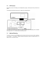
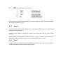
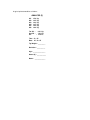
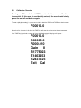
HR1000 USER MANUAL
POULTRY STOCK WEIGHER
Version 1.3
Table Of Contents
1.0
Handling / Storage
1.1
Power Supply
1.1.1
2.0
Battery Charger
1.2
Loadcell
1.3
LCD Contrast
1.4
Indicator Mounting
User Operation
2.1
TARE
2.1.0
House
2.1.1
Print ?
2.1.2
Clear ?
2.1.3
View ?
2.1.4
T (Total)
2.1.5
Av (Average)
2.1.6
CV (Coefficient of Variation)
2.2
ZERO
2.3
Auto Zero Tracking
3.0
Weighing
4.0
Report Printing
5.0
Calibration Overview
5.1
5.2
6.0
Real Time Clock
6.1
7.0
Variables
Gain
Date / Time Setting
Specification
1.0
Handling / Storage
The HR1000 is a precision electronic instrument and requires careful handling. It should be stored
in a dry atmosphere away from direct sunlight.
1.1
Power Supply
The HR1000 is powered by internal rechargeable batteries, the batteries may be charged from the
mains. A 14 hour charge cycle is recommended.
1.1.1
Battery Charger
Important Note :
The Battery Charger is NOT waterproof,
and must NOT be used in a damp
environment.
The battery charger is connected via a two pin lockable plug.
When charging ensure the HR1000 indicator and printer are switched off.
There are NO user serviceable parts contained within the battery charger. Live parts are
enclosed. In the event of a failure return the unit your dealer.
1.2
Loadcell
The loadcell system is attached to the bottom of the indicator. No more than 10 Kg weight should
be placed on the loadcell to avoid mechanical damage to the transducer.
1.3
LCD Contrast
The contrast on the LCD display can be adjusted by varying a trimmer pot on the printed circuit
board.
The location of the (black) trimmer pot is shown on the diagram below :
The contrast may need to be adjusted for optimum viewing angle depending on the indicator
mounting position. This should only be performed by dealer.
1.4
Indicator Mounting
The hook on the top of the HR1000 allows the indicator to be hung at eye level when weighings
are in progress. The indicator is portable allowing the operator to move it to different points in a
poultry house, or to another house.
2.0
User Operation
A diagram of the front panel layout is shown below :
ON
This key turns the unit ON
OFF
This key turns the unit OFF
2.1
TARE This key provides seven functions :
1.
2.
3.
4.
5.
6.
7.
House
Print ?
Clear ?
View ?
T
Av
CV
-
Select house (1 - 4)
Print recorded data
Clear recorded data
View recorded data
Recorded data total
Recorded data average
Coefficient of Variation
When an option is shown the left (TARE) key can be considered as a NO, while the right (ZERO)
key can be considered as a YES.
2.1.0
House
The display shows the currently selected house. The right key (ZERO) may be used to change
the house number from 1 to 4
Once the house number is selected, all functions will now operate using this house number
memory.
When printouts are performed, the house number is shown in brackets to the right of the
ANALYSIS heading, and also at the end of the recording after the House prompt.
2.1.1
Print ?
If Print is choosen, the display will show 'PRINTING' while information is being sent to the printer,
and then automatically return to normal weighing mode.
2.1.2
Clear ?
If Clear is choosen, the display will futher promt :
? SURE !!
The red lamp will flash to warn the operator that data is about to be erased.
The operator can still abort the clear by pressing the NO key (TARE).
If the YES key (ZERO) is pressed then the memory will be cleared and the weighing number will
be reset to 001.
2.1.3
View ?
If view is choosen, the display will show the first weighing in the form :
001
1.56
If the ZERO key is repeatedly pushed, the display will show subsequent data.
The system will cycle around the data as often as required. This allows the user to note all the
weighings if required. (This is usually only necessary if the printer is not available).
The user can abort data viewing at any time by pressing the TARE key.
This is the same data as is printed.
2.1.4
T (Total)
This option shows the total weight of the recorded data, and can be up to 9999.99 kg. This is the
same as the printed total.
2.1.5
Av (Average)
This option shows the average weight of the recorded data, The average weight is calculated as
follows :
Average weight
=
Total weight
----------------------------Number of weighings
The displayed average weight is the same as the printed average.
The average weight can be a maximum of 9.99kg.
2.1.6
CV (Coefficient of Variation)
The percentage coefficient of variation is a mathematical means of expressing the uniformity or
evenness of a flock. The percentage coefficient of variation is calculated as follows :
CV%
=
Weight Range X 100)
---------------------------------Average weight X Factor
Where the Factor is a constant and depend on the size of the sample.
2.2
ZERO
This key sets the scale to zero.
If the zero point has drifted pressing the zero key will correct it.
The zero key is only operational within a small range of the calibrated zero point.
Zero will not be operational if a weight is on the scale and the display will show :
Zero Err
2.3
Auto Zero Tracking
The HR1000 will monitor the slow drift of the zero point and automatically track and compensate
for this error. This feature will only be operational when the displayed weight is close to zero and
the weight remains stable for ten seconds.
3.0
Weighing
Before use the HR1000 indicator batteries should be fully charged. (Typically 14 hours).
The weighing will normally be performed with the printer disconnected, and its portability allows it
to be moved around the house.
The operator should CLEAR the indicator memory, at this stage the weighing number will go to
001.
The ZERO key should be pressed to clear the weight reading. At this stage the display will show :
001 0.00 kg
The operator should now hang the first bird on the hook. The system will wait until the weight has
settled and then record it to memory. The display will now typically show :
002 1.45 kg
The red lamp will light to provide a fast visual indication that the weight has been recorded. (This
is particularily useful in a dark poultry house where the LCD display may be difficult to read).
When the operator removes the bird, the red lamp will go off. At this stage the operator should
perform the next weighing.
The second recording will not be performed until the display has gone to below 50 grams (ie bird
lifted off).
After the second weighing the display will typically read :
003 1.57 kg
As the system is essentially automatic, no keypushes are required during the weighing cycle.
As the weighings are stored permanently in memory, the indicator may be power off at any time
without loss of data. The recording can be continued later if desired.
A maximum of 450 weighings can be stored. Once this limit has been reached the system will
display :
Mem Full
Memory is now full and no more weight recordings can be performed. The operator should now
print out the recorded data and then clear the data.
4.0
Report Printing
The tally roll printer uses standard 50mm paper which can be purchased from most local office
suppliers.
The ribbon has a long life, but if necessary may be purchased from :
DED Ltd
Mill Road
Lydd
Kent
TN29 9EJ
Tel : 01797 320636
The printer will normally only be connected when printing is required. A small toggle switch beside
the printer connector allows the PRINTER to be powered on or off.
To maximise battery life the printer should be switched off when not in use.
Before printing the operator should check the printer is online. ie the GREEN light should be lit on
the printer.
The RED light indicates the printer is powered up.
A typical printout would be as follows :
ANALYSIS (2)
001
002
003
004
005
006
1.50
1.25
1.43
1.37
1.42
1.64
Kg
Kg
Kg
Kg
Kg
Kg
Tot Wt :
8.61 Kg
Avg Wt :
1.43 Kg
CV
: 18.32 %
Time : 12 : 25
Date : 25 / 12 / 97
Tgt Weight : _________
Deviation : __________
Age : _______________
House (2) : ___________
Name : _____________
5.0
Calibration Overview
Warning :
This mode should NOT be entered unless
calibration
is essential. If this mode is accidentally entered, the user should simply
power the unit off and back on again.
To enter calibration mode it is necessary to hold in both the ZERO and TARE keys during power
on. The display will then typically show :
F00010.0
When the first character is flashing, the TARE key will step the display on to the next parameter.
If the TARE key is pushed a number of times the following typical displays will appear :
F00010.0
S00005.0
R000.010
Gain
8
B1778023
Z1463453
S2437325
Exit Cal
The following is a brief description of the displays :
F00010.0
This is the Full scale value which the HR1000 can
display. In this case 10.0 Kg
S00005.0
This is the Span value to be used for calibration. In
this case 5.0 Kg.
R000.010
This is the desired Resolution of the indicator. In
case 10 grams.
D000.000
This is the deadband which may be set. Any weight
below this value will not be recorded.
Gain 4
This is the Gain of the HR1000 loadcell amplifier.
B1778023
This is the current value (in bits) of the A to D
converter, and dynamically changes when the
load is varied.
Z1463453
This is the A to D converter bits which currently
represent the calibrated zero point.
S2437325
This is the A to D converter bits which currently
represent the calibrated span point.
Exit Cal
This gives the user an option to exit the calibration
mode.
this
scale
5.1
Variables
The FULL SCALE, SPAN and RESOLUTION variables can be set as desired in the following way
:
1.
Use the TARE key when the first character is flashing to select the
parameter to be modified.
desired
2.
Press the ZERO key to go into edit mode for the selected parameter.
stage the digit to be modified will be underlined
.
At
3.
digit.
While in edit mode press the TARE key to increment the underlined
4.
When the digit is correct press the ZERO key to select the next digit
modified.
to
this
be
5.
The ZERO key may be pushed until the first digit flashes again. The
ZERO
key will now re-enter the edit mode while the TARE key will
step on to the next
parameter.
5.2
Gain
The A to D converter has a front end amplifier which has a programmable gain which may be set
by the user.
When the Gain variable is selected with the TARE key the ZERO key can now be used to select
the desired gain. The possible gains are :
1
2
4
8
For optimum performance the gain should be set as high as possible, but care should be taken
that the full load signal does not cause the A to D bits to saturate. This may be checked by
looking at the bits display (Bxxxxxxx).
For most common loadcells with a sensitivity of 1 or 2 mV/V a gain of 4 or 8 is usual.
6.0
Real Time Clock
A continually running clock is incorporated in the system. This allows all printouts to be Time and
Date stamped. The clock set mode may be entered by holding in the TARE key during power up.
The following sections describe how to set the date and time.
6.1
Date / Time Setting
The display will typically show the following :
Year
97
If the TARE key is pressed when the first character is flashing the display will advance to the
month display.
If the ZERO key is pressed edit mode for the year will be entered. At this stage the digit to be
modified will be underlined.
While in edit mode if the the TARE key is pushed the underlined digit is incremented.
When the digit is correct press the ZERO key to select the next digit to be modified.
The ZERO key may be pushed until the first character flashes again. The ZERO key will now reenter the edit mode for the year while the TARE key will step on to the month.
The following parameters will typically be displayed :
Year
Month
Day
Hrs
Min
97
03
22
13
26
Once the minutes are set and TARE is again pushed, the display will show WAIT while the clock
is being set.
The clock is battery backed and will continue running even when powered off.
7.0
Specification
Size
165mm X 140mm X 50mm
Enclosure
Stainless steel 304 grade with front panel keyboard
membrane
Display
Eight character LCD display.
Character size 7mm X 8mm
Lamp
3 mm red led (High Intensity)
Keys
ON, OFF, ZERO, TARE
Loadcell
'S' type (20kg)
Display
Resolution
1000 divisions (10 gram)
Calibration
Full Scale
Span
Resolution
Amp Gain
Zero Weight
Span Weight
Battery
Charger
Mains charger 12V DC (NOT WATERPROOF)
Batteries
Eight AA rechargeable batteries
0 to 9.9 kg in 0.1kg increments
0 to 9.9 kg in 0.1kg increments
10g
1, 2, 4, 8
Recorded with no weight loaded
Recorded with span weight loaded
Connections
Printer :
Charger:
5 pin lockable plug
2 pin lockable plug
Memory
The following data is held during power down :
Zero point
Tare weight
All printer weight data
Weight Total
Weight Average
Coefficient of Variation
Loadcell
Exitation voltage : 5 Volts DC
Resolution
16 Million bits internal
Printer
DPN233-24-V.24
Interface
Serial
Paper
50 mm width