1
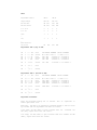
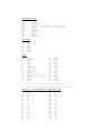
HYTEC ELECTRONICS LTD
5 Cradock Road, Reading, Berkshire, RG2 0JT, U.K.
Tel: +44 (0) 118 9757770 Fax: +44 (0) 118 9757566
Email: [email protected]
VAT Reg No. 285 2479 27
Web Site: www.hytec-electronics.co.uk
[1Q]
User Manual and Parts List
DAC 670 MK5 CAMAC OPTO
ISOLATED DUAL 18 BIT DAC
(18 Bit Binary Resolution - 18 Bit
Absolute Accuracy)
Also at 64, Amy Street, Leicester, LE3 2FB, U.K. (Sales & Service - North)
Directors: R.R.T.Tatham, G.S.Cross, Secretary: R.R.Tatham
Registered Office: 5, Cradock Road, Reading, Berkshire, RG2 0JT Incorporated in England No. 1246940
Issue: 2
Doc: Hytec DAC 670
Doc no.: 55
Page 1
Author: RRTT
Date: 25.11.98
DAC 670 MK5 CAMAC OPTO ISOLATED DUAL 18 BIT
(18 Bit Binary Resolution - 18 Bit Absolute Accuracy)
DESCRIPTION
Overview
The 670 Mk5 is high precision Dual 18 bit optically isolated Digital to
Analog Converter (DAC), designed to be used as a accurate voltage
source or as the “fine trim" on a high voltage system, such as the
focus control on an electron microscope. It may also be used to provide
very accurate ramp voltages to test ADC systems. General applications
include Automatic test equipment, scientific
instrumentation, beam
positioners and very high quality digital audio.
Description
It is a single width CAMAC module, which contains two completely
separate opto-isolated 18 bit DACs.
Each converter circuit includes facilities such as references and power
regulators so as to make them totally separate be truly Isolated the
module needs to be powered by two transformer isolated, + 21 - 30 Volt
_
stabilised power supplies, connected via the two 37 way Cannon
sockets.
However, the CAMAC power supplies may be selected, if
desired, at the loss of isolation.
The data for the DAC is stored in to counting registers formed from
parallel data entry up/down synchronous counters.
These counting registers may be loaded, incremented or decremented and
read via CAMAC Command.
In addition, four optically isolated digital inputs allow either
register to be incremented or decremented via the front panel.
Each time the data stored in the DAC data register is altered an
automatic micro sequence is started that transfers the data from the
register into the main DAC in such a way as to minimise transmission
glitches from the analog output.
This circuit also triggers a monostable multivibrator that is used to
drive an opto isolator to provide a digital output signal for each
DAC for the whole time the Analog value from the DAC is in transition,
changing from one value to the next. This is very useful when testing
ADCs to know when the output is not 'True'.
The data from the data registers is passed through opto- isolators and
fed into the two separate hybrid laser trimmed DAC chips which contain
data latches and current to voltage amplifiers.
The Analogue output is passed in voltage form from the DAC outputs into
a precision power amplifier working at unity gain.
This has been
included so that a fully sensing four wire output system can be
provided,
together
with
allowing high output currents without
self-heating effects on the DACs.
As can readily be seen to get near 18 bit performance over any
reasonable length of output lines, a fully sensing circuit
is
necessary.
Consider the case, when used on +10V full scale 1 LSB bit
is about 38 uV. A 30 m ohms wire and connector resistance with a 5 mA
load would give a 150 uV error, 4 bits.
To help get over these problems. The output amplifier has two stages.
The first is a very temperature stable and low noise high gain
operational amplifier within the DAC chip, with a + 5mA drive
_
capability. The second is a high power unity gain power driver. A wire
link allows the first amplifier alone to be used for low current work
and the power buffer together with the precision amplifier for high
power work. In either case a fully symmetrical differential amplifier
circuit is used.
Precision temperature matched resistor networks
inside the DAC chip have been employed so as to give peak performance.
The power output driver amplifier is capable of providing + 50mA.
There are two output options where sense links
one set at a time, i.e. if Lemo output is used
of the Lemo cable, if the 37 way Cannon output
will be at its far end. Note: the 37 way plug
give the analog power inputs.
must be fitted, but only
fit links at the far end
is chosen then the links
must always be used to
A test socket is supplied with each unit, just to get it going. It
does not give isolated outputs but does power up the system.
(Try
minimize the output current used to avoid heating up the module).
to
The DACs have four programmable signal ranges, which may be selected
via CAMAC Commands. (F30 Ax Bit sets) The first two are Unipolar 0V to
10V and 0V to 5V, if the output is being externally powered by floating
supplies, this may be referenced so as to be 0 to +10V or 0 to -10V
etc, It is coded in straight binary. The second two ranges are + 10V
and + 5V coded in 2's Compliment binary. (Bit 18 MSB). Other types of
coding may wire linked, see the circuit diagram for details.
As two separate multiturn trim components are used for each range,
there is no change in setup, between ranges, however, due to the use
of relays, there is a delay time of up to 10 mS between goings from one
output range to the other. This delay is only present when going from
Range to Range not value to value!
SPECIFICATION
Analog Output
Full 4 wire Sense Circuit
Mode A
Mode B
+ 5 mA Output Current all Ranges
_
+ 50 mA Output Current all Ranges (standard)
Note: one pair (only) of sense links must be made externally to the
unit, either via the Lemo or 37 way Cannon socket.
If not fitted
uncontrolled voltages, up + 15 V may come from the outputs.
_
Setting Time
10V step
LSB change
45 uS +1/2 LSB (= 0.00019 %) of final value
6 uS
+1/2 LSB (= 0.00019 %) of final value
(Glitch energy is 500 mV x 500nS for major carry)
Output Noise
Band Width
0 - 100KHz
60 uV RMS Bipolar
20 uV RMS Unipolar
Temperature Coefficients
Gain
Offset
+ 5 ppm of FSR /oC max.
+ 1 ppm of FSR /oC max.
(5 C - 40 C)
(5 C - 40 C)
_
Voltage Range
Software Set
See Chart for details.
NOMINAL OUTPUT VOLTAGE VALUES
0.00000 V to +9.99996 V
0.00000 V to +4.99998 V
-10.00000 V to +9.999924 V
-5.00000 V to +4.999962 V
Isolation voltage
500 Volts peak to
peak.
peak
max. Normal Working voltage + 250 V peak to
Note: Due to the packing density used in the module it is not to be
used to isolate Mains voltages etc. If it is used in a High voltage
system always put it at the low voltage end of the circuit, and please
take all safety precautions.
Output Accuracy
True 18 bit absolute accuracy at 20oC ambient.
No missing Code 0oC-50oC.
(After 20 min warm-up).
Isolated Digital Output (set via F30/F28 functions)
4 Per DAC
OFF state 0 - 30 V on sink 5 mA at 0.5 V
DAC output stable pulse output unstable signal
TTL signal isolated to the DAC in question supply.
transition)
Sinks 8 loads
Low = 1 (DAC in
Isolated Digital Inputs
4 per DAC
Input TTL compatible 0 - 1 mA = logic "0"
8 - 20 mA = logic "1"
Reverse diode protected, current limited by 270 ohms resistor.
Normally the + end is taken to +5 V and - end to the TTL output.
Isolated Digital Control Inputs
Increment DAC (if enabled)
Decrement DAC (if enabled)
Set DAC LAM (if selected by wire link option)
0 - 1 mA = logic "0"
8 - 20 mA = logic "1"
"D" TYPE PLUG
Input Bit 4 (+I)
Input Bit 3 (+I)
Input Bit 2 (+I)
Input Bit 1 (+I)
Bit A3(Bit 4)Open Coll.O/P
Bit A2(Bit 3)Open Coll.O/P
Bit A1(Bit 2)Open Coll.O/P
Bit AO(Bit 1)Open Coll.O/P
LAM input (+I)
Decrement Data input (+I)
Increment Data input (+I)
Isolated Analog Earth(Ret)
CAMAC -24V Output (Non Iso)
Camac 0V Output (Non Iso)
Camac +24V Output (Non Iso)
Isolated Analog Earth
Isolated +5V Line(ret.P22)
Main Analog power output
Main Analog power output
\
| \
|
\
+|O 19 \
| 37 O \+|O 18
|
| 36 O |+|O 17
|
| 35 O |+|O 16
|
| 34 O |+|O 15
|
| 33 O |+|O 14
|
| 32 O |+|O 13
|
| 31 O |+|O 12
|
| 30 O |+|O 11
|
| 29 O |+|O 10
|
| 28 O |+|O 9
|
| 27 O ||O 8
|
| 26 O |+
|O 7
|
| 25 O ||O 6
|
|
24 O||O 5
|
|
23 O|+
-|O
4 |
|
22 O|+|O
3 |
|
21 O|-|O
2 |
|
20 O|+
+|O
1 /
|
/
| /
|/
Input Bit 4 (-I)
Input Bit 3 (-I)
Input Bit 2 (-I)
Input Bit 1 (-I)
Bit A3 (Bit 4)output emitter(-I)
Bit A2 (Bit 3)output emitter(-I)
Bit A1 (Bit 2)output emitter(-I)
Bit A0 (Bit 1)output emitter(-I)
LAM input (-I)
Decrement Data Input(-I)
Increment Data Input(-I)
Data valid open Coll.O/P(Ret.P8)
-24V Power input (21-30V) Ret.@P22
Isolated Analog Earth
+24V Power input(21-30V (Ret.@ P4)
Isolated Analog Earth
Main Analog power sense return
Main Analog power sense return
AS VIEWED FROM FRONT OF MODULE (MK2 upside down)
Notes
+I shows a current input paired to -I, normally driven by 10mA at 3V.
(21-30V) + The floating stabilised input voltage range.
Open Coll. + Open Collector transistor, collector, (NPN transistor).
@PX = PL1/2 Pin Number X
O/P = Output
Ret. = Return
Non Iso. = Non Isolated.
670 MK2 FUNCTION CODES
F0
A0
Read DAC 'A' Counting Register, gives 18 bits of data,
gives 'X' and 'Q'. (Note if LK3 and LK4 are made then 20
bit data is possible).
F0
A1
Read the DAC 'B' Counting Register, gives 18 bits of
gives 'X' and 'Q'.
F0
A2
Read the opto-isolated digital data inputs, data field 8
bits. Bits 1-4 are from DAC 'A' input socket. Bits 5-8 are
from DAC 'B' input socket.
Both sockets are 37 way
Cannons, gives 'X'.
data,
See the 670 Control data Chart for both F0 A2 and F0 A3.
F0
A3
Read the state of the bit set control lines, 16 bit data
field, gives 'X' .Note: Data Read back bits are Sub address
plus 1.
Bits 1-4 are opto isolated data output lines
(via PL1).
Bits 5-8 are
(via (PL2).
for
DAC
'A'
opto isolated data output lines for DAC 'B'
Bits 9-12 are control bits for DAC 'A' (See F28 and F30 for
details)
Bits 13-16 are control bits for DAC 'B' (See
for details)
F28
and
F30
Bits 1-4 may be used as desired by the program.
Bits 5-8 may be used as desired by the program.
Bit 9 is used by DAC A to control Unipolar or Bipolar
operation
"0"= Unipolar, "1"= Bipolar.See table for detail.
Bit 10 when set to "1" enables the front panel increment of
DAC 'A'.
Bit 11 when set to "1" enables the front panel decrement of
DAC 'A'.
Bit 12 is used by DAC A to control its output range,"0"= 0V
- 10V or + 10V. "1" = 0V -5V or + 5V. See table for
_
_
detail.
Bit 13 is used DAC B to control
operation
or 0V - 5V, "1" = + 10V or + 5V.
_
_
Bit
DAC
Unipolar or Bipolar
"0" = 0V - 10V
14 when set to"1" enables the front panel increment of
'B'.
Bit 15 when set to "1", enables the front
of DAC 'B'.
panel
decrement
Bit 16 is used by DAC B to control its output range,
"0"= 0 - 10V or + 10V. "1" = 0 - 5V or + 5V operation. See
table for details.
F2
A0
Read and Clear DAC 'A' Counting Registers, 18 bits of data
gives 'X' and 'Q' (Note: Data field may be extended to 20
bits via LK3 and 4).
F2
A1
Read and Clear DAC 'B' Counting Registers, 18 bits of data
gives 'X' and 'Q' (Note: Data field may be extended to 20
bits via LK3 and 4).
F2
A3
Read and Clear DAC 'A' Counting Registers, also
'B' LAM, gives 'X' and 'Q'.
F8
A0
Test LAM, 'Q' = DAC 'A' LAM set and enabled, gives 'X'.
F8
A1
Test LAM, 'Q' = DAC 'A' LAM set and enabled, gives 'X' .
F8
A15
Test all LAM's in the module, 'Q' = DAC 'A' or 'B' LAM set,
gives 'X'.
F9
A0
Clear DAC 'A' Counting Register, gives 'X'.
F9
A1
Clear DAC 'B' Counting Register, gives 'X'.
F9
A2
Clear all 16 bit set lines to zero, gives 'X'.
F9
A15
Clear both DAC 'A' and 'B' Counting Registers, Clear and
disable all LAM's same action as ZS2 on Dataway, gives 'X'.
F10
A0
Clear DAC 'A' LAM, gives 'X'.
F10
A15
Clear both DAC 'A' and 'B' LAM's, gives 'X'.
F16
A0
Overwrite the DAC 'A' Counting Register, 18 bit data field,
(Note: Data field may be 20 bits if LK3 and LK4 are made)
gives 'X' and 'Q'.
F16
A1
Overwrite the DAC 'B' Counting Register, 18 bit data field,
(Note: Data field may be 20 bits if LK3 and LK4 are made)
gives 'X' and 'Q'.
F16
A2
Overwrite the DAC 'A' Counting Register and clear
'A' LAM, gives 'X' and 'Q'.
F16
A3
Overwrite the DAC 'B' Counting Register and clear the DAC
'B' LAM, gives 'X' and 'Q'.
F24
A0
Disable DAC 'A' LAM, gives 'X'.
F24
A1
Disable 'B' LAM, gives 'X'.
F24
A15
Disable DAC 'A' and 'B' LAM, gives 'X'.
F25
A0
Increment the DAC 'A' Counting Register by 1, independent
of the state of the bit set enable, gives 'X' and 'Q'.
F25
A1
Increment the DAC 'B' Counting Register by 1, independent
of the state of the bit set enable, gives 'X' and 'Q'.
F25
A2
Decrement the DAC 'A' Counting Register by 1, independent
of the state of the bit set enable, gives 'X' and 'Q'.
F25
A3
Decrement the DAC 'B' Counting Register by 1, independent
of the state of the bit set enable, gives 'X' and 'Q'.
F26
A0
Enable DAC 'A' LAM, gives 'X'.
F26
A1
Enable DAC 'B' LAM, gives 'X'.
F26
A15
Enable both 'A' and 'B' LAM's, gives 'X'.
clear
the
DAC
DAC
F27
A0
Test the DAC 'A' LAM before enable latch, 'Q' = "1" if
set, gives 'X'.
F27
A1
Test
set,
F27
A2
Test the DAC 'A' Output is stable, 'Q'= "1" if it is, gives
'X'.
F27
A3
Test the DAC 'B' Output is stable, 'Q' = 1 if it is,
'X'.
NOTE:
Hytec bit set commands on the 670 are controlled by individual
F30 (set) and F28 (clear) commands via sub address, each command
gives the "X" response:F30 Ax set that bit only, ie F30 A6 sets bit 6, which Reads back
via R7.
F28 Ax clears that bit only,ie F28 A6 clears bit set bit 6 and
read back R7.
All bits are clear simultaneously by the clear commands F9 A2 and
the general clear Z.S2 Also cleared by the power up Clear system.
All F28 & F30
sub
the DAC 'B' LAM before enable latch,'Q' = "1" if LAM
gives 'X'.
address
codes
0
-
15
give
the
"X"
gives
response.
F28 A0-A3 'Clear'
F30 A0-3 'Set '
DAC 'A' Bit set opto outputs via PL1.
(Read back via F0 A3, A0=Bit 1, A3 = Bit R4 when
set) (ie The sub address number plus 1 gives F0 A3
Read back bit number).
F28 A4-A6 'Clear'
F30 A4-A7 'Set'
DAC 'B' Bit set opto output via PL2 (Read back via
F0 A3, A4 = Bit R5, A7 = Bit R8 when set,)
F28 A8 'Clear'
F30 A8 'Set'
Bit set DAC 'A' Mode. Clear= Unipolar.
Bipolar. Read back bit R9.
Unipolar coded in straight binary bit 18 MSB.
+ 10V Range coded 2's complement Binary.
_
F28 A9 'Clear'
F30 A9 'Set'
Front panel increment of the data value in
DAC 'A's' data Register/Counter via PL1 opto input.
(Read back via F0 A3 bit R10).
F28
Set = Enable front panel decrement of the data
value in.
DAC 'A's' data register/ counter, via PL1 opto
input. (Read back via F0 A3 bit R11).
A10
'Clear'
F30 A10 'Set'
F28 A11 'Clear'
F30 A11 'Set'
F28 A12 'Clear'
F30 A12 'Set'
_
LAM
F28 A13 'Clear'
F30 A13 'Set'
F28 A14 'Clear'
F30 A14 'set'
F28
A15
'Clear'
F30 A15 'Set'
DAC A Range control, Clear= 0 to 10V or + 10V mode.
_
Set= 0 to 5V or + 5V range. Read back via F0 A3 bit R12.
Bit set DAC 'B' Mode 'clear' = 0 - 10V or + 10V mode.
0 - 10V mode, Straight Binary code Bit 18MSB.
Set = + 10V Range bit, code = 2's complement Binary
_
(Read back via F0 A3 + 10V =R 13 set).
Set = Enable front panel increment of the
data value in DAC 'B' data register/ counter, via
PL2 opto input. (Read back via F0 A3 bit R 14)
Set = Enable front panel decrement of the
data value in DAC 'B's' data register/ counter, via
PL2 opto input. (Read back via F0 A3 bit 15)
DAC
B
range
control bit, clear = 0 to 10V or +
_
10V.
Set= 0 to 5V or + 5V range. Read back via F0 A3 bit_
16.
670 LINK CHART
(See 670 Circuit Diagram)
LK1
___
A-C
___
LAM is set on DAC 'A'
by
an
external
Current
(5uA) into the opto input pair on PL1 pin 11 (+)
and 29 (-). Equivalent circuit 1.6V Zener diode
with 270 Ohm Resistor.
LK1
___
A-B (standard)
___
LAM
is
set
after
a preset time ( 50uS) after
command which has altered the state of the DAC
'A', when the 'New' D.C. value will be true and
stable.
LK2
___
A-C
___
LAM is set on DAC
'B'
by
an
external
Current
(5mA) into the opto input pair on PL2 pin 11(+)
and 29(-). Equivalent circuit 1.6V Zener diode
with 270 Ohm resistor.
LK2
AB
_________
(standard)
LAM
is
set after a preset time (50us) after a
command which has altered the state of the DAC
'B', when the 'New' D.C. value will be true and
stable.
LK3
___
Open as standard when closed makes both the
Register 19 bits
extra to the DAC)
LK4
___
Open as standard
long.
when
Data
(Does not do anything
closed
makes
both
Data
Registers 20 bits long (given LK3 also closed).
LK5
___
Open-
Special
Function
Expansion
option,not
implemented.
LK6
___
LK6
___
A-C (Standard)
___
A-B
___
This link adds in the high power (+ 50mA) Driver
_
circuit on DAC 'A'.
This mode takes out the
High
power
driver
and
restricts
the available output current to + 5mA,
_
it does improve the Noise performance and reduces
the internal temperature rise in the module.
LK7
___
LK7
___
A-C (Standard)
___
A-B
___
This Link adds in the High power (+ 50mA)
_
circuit on DAC "B".
This
mode
takes
Driver
out the High power driver and
restricts the available output current to + 5mA,
_
it does improve the noise performance and reduces
the internal temperature rise in the module.
Note
Each DAC has links on the internal +5V +18V +15V
and -18V & -15V power line, these are for Test
purposes and must normally be made.
+5V Power has been made available on pin 3 of PL1
and 2 it must be restricted to 50 mA max. to
avoid overheating.
Table
Programme Control
DAC A
DAC B
Output Range
Bit Set
Bit Set
F30 Ax Sets
F28 Ax Clears
A8
A8
A12
A12
A15
A15
0 to 10 V
0
0
0
0
0 to 5V
0
1
0
1
+10V
_
1
0
1
0
+5V
_
1
1
1
1
R9
R12
R13
R16
Read back bit
Via F0 A3
A11
A11
Adjustments DAC A (Top of PCB)
VR
1
0 - 10V
Gain
VR
VR
VR
VR
3
2
4
6
- 10V
- 5V
- 5V
10V
Offset
Gain
Offset
Gain
VR
8
10 V
Offset
VR7
VR
5
5 V
Gain
VR
7
0
0
0
+
_
+
_
+
_
+
_
PCB LAYOUT PATTERN SET UP VOLTAGES
__________________ _______________
A
B
A
B
VR1 VR2
9.999962 V + 4.999981 V
VR3 VR4
0.000000 V
0.000000 V
VR5 VR6
4.999962 V + 9.999924 V
5 V
Offset
VR8
-5.000000 V - 10.000000 V
Adjustments DAC B. (Bottom of PCB)
VR
9
0 - 10V
Gain
VR
VR
VR
VR
11
10
12
14
- 10V
- 5V
- 5V
10 V
Offset
Gain
Offset
Gain
VR
16
10 V
Offset
VR15 VR16
VR
13
5 V
Gain
VR
15
0
0
0
+
_
+
_
+
_
+
_
PCB LAYOUT PATTERN SET UP VOLTAGE
__________________ ______________
A
B
A
B
VR9 VR10
9.999962 V + 4.999981 V
VR11 VR12
0.000000 V
0.000000 V
VR13 VR14
4.999962 V + 9.999924 V
5 V
Offset
-5.000000 V - 10.000000 V
Adjustment Procedures
First let the module warm up for
normal operational load.
20
minutes
into
an
equivalent
to
Basically, the DAC to be adjusted is switched between 0 and full scale
by software and the adjustments are made as follows:0-10V range, set VR3 (VR11) to give 0.000000V then
VR1 (VR9), repeat until both are correct.
set
9.999962V
via
0-5V range, set VR4 (VR12) to give 0.000000V then set 4.999981V via VR2
(VR10), repeat until both are correct.
+10V range and +5V range, it will be found the the adjustment
_
_
potentiometer on each range interact and a strategy of halving the
apparent areas on each adjustment together with a lot of patience
should produce the correct result with repeated adjustments.
+10V range, set VR8 (VR16) to give -10.000000V then set +9.999924V
_
VR6 (VR14), repeat until both are correct.
via
+5V range, set VR7 (VR15) to give -5.000000V then set VR5 (VR13) to
_
give 4.999962V, repeat until both are correct.
Parts List: 670
Page 1
PARTS LIST FOR HYTEC 670 MK V
Integrated Circuits
1
2
3
4
5
6
7
8
SN74LS123N
SN74LS132N
SN74LS32N
SN7414N
SN7401N
SN74LS32N
SN74LS08N
N82S100 (P670 P8)
9
10
11
12
13
14
SN74LS123N
SN74LS123N
SN74LS123N
SN74LS375N
1
SN74LS279N
1
SN74S188N(P670/P114) 1 (S)
S
S
SN74S188N(P670/P15) 1 (S)
S
S
SN74S188N (P670/P1)6 1 (S)
S
S
SN74622N
1
SN74S244N
6
SN74S244N
SN74S244
F93L34B
2
F9334B
ILQ05
2
ILQ05
SN74LS132N
DM8092N
1
SN74LS08N
1
SN74LS622N
SN74LS244N
SN74LS244N
SN74LS244N
SN74S240N
1
HP2531
23
HP2531
HP2531
HP2531
SN74LS14N
SN74LS14N
SN74LS14N
15
16
17
18
19
20
21
22
23
24
25
26
27
28
29
30
31
32
33
34
35
36
37
38
39
4
2
2
5
1
2
1 (S)
S
S
40
41
42
43
44
45
46
47
SN74LS14N
SN74193N
SN74193N
SN74193N
SN74193N
SN74193N
N8234B
SN75452N
48
49
50
51
52
53
HP2630
SN74193N
SN74193N
SN74193N
SN74193N
SN74193N
54
HP2630
55
HP2531
56
57
58
59
60
61
61
63
64
65
66
67
68
69
70
71
72
73
74
75
76
77
78
79
80
81
82
HP2531
HP2531
HP2531
HP2531
HP2531
HP2531
HP2531
HP2531
HP2630
HP2630
HP2531
HP2531
HP2531
HP2531
HP2531
HP2531
HP2531
HP2531
HP2531
HP2630
AD1139K *
2
AD1139K *
BUF634 (on special PCB)
OP 07C
BUF634 (on special PCB)
OP 07C
SN74S188N
(S)
10
1
1
5
(S) = socketed
S
S
* = AD1139J for 17 bit units (absolute accuracy) Normal 18 bits.
Voltage Regulations
VReg
VReg
VReg
VReg
VReg
VReg
VReg
VReg
VReg
VReg
1
2
3
4
5
6
7
8
9
10
uA7818C )
uA7918C )
uA7818C )
All mounted on the Rear panel
uA7918C )
With double mica insulator Kits
uA7815C
uA79L15C
LM2931A T5.0
uA7815C
uA79L15C
LM2931A T5.0
Transistors
TR1
TR2
TR3
TR4
TR5
TR6
TR7
ZTX314
2N3903
2N3903
2N3903
2N3903
2N3903
2N3903
(1)
(6)
Diodes
D1
D2
D3
D4
D5
D6
D7
D8
D9
D10
D11
D12
D13
D14
D15
D16
IN5401
1
BZY88C3V0
1
IN914
7
IN914
IN914
IN914
HP5082-2811
4
HP5082-2811
HP5082-2811
HP5082-2811
4
IN4004
IN4004 * (fit backwards)
IN4004
IN4004 * (fit backwards)
IN4004
IN914
D17
D18
D19
D20
D21
D22
D23
D24
D25
D26
D27
D28
D29
D30
D31
D32
IN4004
IN914
IN4004
IN914
IN4004
IN914
IS121
1S121
1S121
1S121
1S121
1S121
IN4004
IN4148
IN4148
IN4148
* = fit back to front not as shown on the ident screen.
Note: 1N4148 or 1N914 or 1N916 may be used,in place of each other.
Resistors - all Mullard MFR25 +1% 50ppm Metal Film
R1
R2
R3
R4
R5
R6
R7
R8
R9
R10
R11
R12
R13
R14
R15
R16
R17
R18
22K
10K
220
27K
15K
220
1K
1K
1K
1K
560
560
560
560
270
270
560
560
1
5
6
1
5
8
6
44
R41
R42
R43
R44
R45
R46
R47
R48
R49
R50
R51
R52
R53
R54
R55
R56
R57
R58
270
270
270
270
270
270
270
270
270
270
270
270
220
220
270
270
270
270
R19
R20
R21
R22
R23
R24
R25
R26
R27
R28
R29
R30
R31
R32
R33
R34
R35
R36
R37
R38
R39
1K
1K
470
470
180k
180K
10K
15K
10K
4.7K
2.2K
1K
1K
15K
270
270
270
270
270
270
270
R40
270
R80
R81
R101
R84
41.2K + 0.25% Vishay
_
2.15 + 0.25% Vishay
_
1M ohm + 5% film (low TC)
_
15K
R85
15K
R105
R86
1K + 2%
_
1K
50 + 2%
_
68 + 2%
_
68 + 2%
_
47 2.5W or BZX 70 C7V5
R106
1K + 2%
_
1K + 2%
_
51 + 2%
_
68 + 2%
_
68 + 2%
_
47 2.5W or BZX70 C7V5
R107
R108
NOT FITTED
NOT FITTED
R109
NOT FITTED
R110
NOT FITTED
R111
NOT FITTED
3.3K
20K + 2%
_
41.2K + 0.25% Vishay
_
41.2K + 0.25% Vishay
_
41.2K + 0.25% Vishay
_
2K + 0.25% Vishay
_
1M ohm + 5% film low TC
_
Not fitted
Not fitted
R112
R113
NOT FITTED
NOT FITTED
R114
NOT FITTED
R115
NOT FITTED
R116
NOT FITTED
R117
100K ohms
R118
820
R82
R83
R87
R88
R89
R90
R91
R92
R93
R94
R95
R96
R97
R98
R99
R100
R59
R60
R61
R62
R63
R64
R65
R66
R67
R68
R69
R70
R71
R72
R73
R74
R75
R76
R77
R78
R79
2
2
5
R102
R103
R104
270
270
270
270
270
270
270
270
270
270
270
270
270
270
270
270
220
220
3.3K
20K
41.2K + 0.25% Vishay
_
41.2K + 0.25% Vishay
_
Resistor Packs (all common power unless noted)
RP1
RP2
RP3
RP4
RP5
RP6
RP7
1K
1K
1K
10K
330
330
270
(9 pin)
(9 pin)
(9 pin)
(10 pin)
(8 pin 4R's)
(8 pin 4R's)
(9 pin)
4
1
2
2
RP8
RP9
RP10
RP11
RP12
2.2K
2.2K
3.3K
3.3K
560
(10 pin)
(10 pin)
(10 pin)
(10 pin)
(9 pin)
4
Variable Resistors
VR1
VR2
VR3
VR4
VR5
VR6
VR7
VR8
VR9
VR10
VR11
VR12
VR13
VR14
VR15
VR16
50K
50K
50K
50K
50K
50K
50K
50K
50K
50K
50K
50K
50K
50K
50K
50K
Muliturn
"
"
"
"
"
"
"
"
"
"
"
"
"
"
"
BOURNS
BOURNS
BOURNS
BOURNS
BOURNS
BOURNS
BOURNS
BOURNS
BOURNS
BOURNS
BOURNS
BOURNS
BOURNS
BOURNS
BOURNS
BOURNS
3262
3262
3262
3262
3262
3262
3262
3262
3262
3262
3262
3262
3262
3262
3262
3262
16
Capacitors
C1
C2
C3
10uF 35V M.C.T
47uF 20V M.C.T
22uF 6V M.C.T
C4
C5
C6
C7
C8
C9
22uF 6V M.C.T
330pf 63V Ceramic
56pf 63V Ceramic
2.2nF +10% 63V Ceramic
__
2.2nF 63V Ceramic
2.2nF 63V Ceramic
C10
2.2nF 63V Ceramic
C22
C11
2.2nF 63V Ceramic
C23
C12
2.2nF 63V Ceramic
C24
C25
C37
C31
15 MFD +20% 16V Tant Bead
_
15 MFD +20% 16V Tant Bead
_
10 MFD +20% 25V Tant Bead
_
47 MFD +20% 6.3V Tant Bead
_
10 MFD +20% 25V Tant Bead
_
10 MFD +20% 25V Tant Bead
_
0.1 MFD +80% -20% 100V
C32
Mono Ceramic
0.1 MFD +80% -20% 100V
C26
C27
C28
C29
C30
C33
C34
C35
C36
C50
C52
1
1
2
C13
C14
C15
3
1
6
C16
C17
C18
C19
C20
C21
C38
C39
C40
C41
C42
C43
C44
Mono Ceramic
10 MFD +20% 25V Tant Bead
C45
_
10 MFD +20% 25V Tant Bead
C46
_
0.1 MFD +80% -20% 100V
C47
Mono Ceramic
0.1 MFD +80% -20% 100V
C48
Mono Ceramic
C49
10 MFD +20% 25V Tant Bead
_
10 MFD +20% 25V Tant Bead
_
0.1 MFD +80% -20% 100V Mono
330pf 63V Ceramic
330pf 63V Ceramic
820pf +10% 63V Ceramic
_
820pf 63V Ceramic
180pf 63V Ceramic
220pf 63V Ceramic
180pf 63V Ceramic
2
2
220pf 63V Ceramic
6.8 MFD +20% 35V Tant Bead 4
_
6.8 MFD +20% 35V Tant Bead
_
10 MFD +20% 25V Tant Bead 12
_
10 MFD +20% 25V Tant Bead
6.8 MFD +20% 35V Tant Bead
_
6.8 MFD +20% 35V Tant Bead
_
10 MFD +20% 25V Tant Bead
_
10 MFD +20% 25V Tant Bead
_
15 MFD +20% 16V Tant Bead
_
15 MFD +20% 16V Tant Bead
_
10 MFD +20% 25V Tant Bead
_
47 MFD +20% 6.3V Tant Bead
_
10 MFD +20% 25V Tant Bead
_
10 MFD +20% 25V Tant Bead
_
0.1 MFD +80% -20% 100V Mono
Ceramic
0.1 MFD +80% -20% 100V Mono
Ceramic
C51
0.1 mfd +80% -20% 100V Mono
Ceramic
Ceramic
Note: All ceramic Caps. <330 pF are + 2% 63 Volts.
_
All ceramic Caps. >330 pf but <2200 pF are +10% 63V.
_
MCT = Metal cased Tantalum.
Plugs
PL1
PL2
37 Way Cannon 'D' type plug, with female screw lock retention.
37 Way Cannon 'D' type plug, with female screw lock retention.
Sockets
SK3
SK4
4 Pole Lemo RA0304) mating part LEMO F0304NY
4 Pole Lemo RA0304) "
"
"
"
Relays
RL1)
RL2)
RL3)
RL4)
RL5)
RL6)
RL7)
RL8)
RL9)
RL10)
RL11)
RL12)
Single Pole Change Over Farnell No. 224-480
(Siemens Part No. V23026-A1001-B201 (5V Coil))
Dual Pole Change Over Farnell No. 177-825
(Ormron G6H H-2100 (5V Coil))
Single Pole Change Over Farnell No. 224-480
(Siemens Part No. V23026-A1001-B201)
Dual Pole Change Over Farnell No. 177-825
(Ormron G6H-2100)
LED
1 off Red 0.2 inch + clip
Chassis Kit
1 off Benney CM 1 Kit (long screen)
1 off Jacking Screw
I.C. Sockets
1 off 28 pin turned pin low profile (IC8)
4 off 16 pin turned pin low profile (IC14-16 and IC82)
Heat Sink
2 off Hytec special of Elantec Power Buffers
Fuses
FS1
FS2
FS3
FS4
FS5
FS6
FS7
1A
1A
3A
0.25A
0.25A
0.25A
0.25A
-
0.5A
0.5A
0.5A
0.5A
Fuse Holders
6 off normal
6 off IC socket type
P.C.B.
1 off 670 issue 5
Note : There are wire mods to this PCB, under IC's.