1
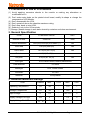
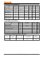
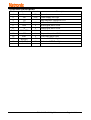
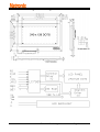
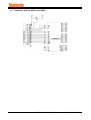
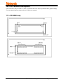
LCD Module User Manual
Customer
:
MASS PRODUCTION CODE
: TG240128D-01XA0
DRAWING NO.
: m-TG240128D-01XA0_A00
Approved By Customer:
Date:
Approved By
Checked By
TG240128D-01XA0_A00
Prepared By
Page 1 of 11
Contents
1. Precautions in Use of LCD Moudule-----------------------------------P3
2. General Specification-------------------------------------------------------P3
3. Absolute Maximum Ratings-----------------------------------------------P3
4. Electrical Characteristics--------------------------------------------------P4
5. Backlight Information-------------------------------------------------------P4
6. Optical Characteristics-----------------------------------------------------P5
7. Interface Description--------------------------------------------------------P6
8. Contour Drawing & Block Diagram--------------------------------------P7
9. Application circuit----------------------------------------------------------P8
10.LCD Function Description -----------------------------------------------P9
11. LCD RAM map -----------------------------------------------------------P9
12. Standard Character pattern -------------------------------------------P10
13. Revision records------------------------------------------------------P11
TG240128D-01XA0_A00
Page 2 of 11
1. Precautions in Use of LCD Module
(1) Avoid applying excessive shocks to the module or making any alterations or
modifications to it.
(2) Don’
t make extra holes on the printed circuit board, modify its shape or change the
components of LCD Module.
(3) Don’
t disassemble the LCM.
(4) Don’
t operate it above the absolute maximum rating.
(5) Don’
t drop, bend or twist LCM.
(6) Soldering: only to the I/O terminals.
(7) Storage: please storage in anti-static electricity container and clean environment.
2. General Specification
ITEM
STANDARD VALUE
UNIT
Number of dots
240X128
Dots
Outline dimension
144.0(W)X104.0(H)X13.0MAX.(T)
mm
View area
114.0(W)X64.0(H)
mm
Active area
107.95(W)X57.55(H)
mm
Dot size
0.40(W)X0.40(H)
mm
Dot pitch
0.45(W)X0. 45 (H)
mm
LCD type
STN,Yellow-Green,Positive,transflective
View direction
6 o’
clock
Backlight
LED, Yellow-Green
Controller
LC7981
Interface
8-bit parallel
3. Absolute Maximum Ratings
SYMBOL
MIN.
MAX.
UNIT
Operating Temperature
TOP
-20
-
+70
℃
Storage Temperature
TST
-30
-
+80
℃
VI
-0.3
-
VDD +0.3
V
Supply Voltage For Logic
VDD
0
-
5.5
V
Supply Voltage For LCD
VDD-VEE
0
-
20.0
V
ITEM
Input Voltage
TG240128D-01XA0_A00
TYPE
Page 3 of 11
4. Electrical Characteristics
ITEM
SYMBOL
Logic Voltage
VDD-VSS
Supply Volt.For LCD
VDD-VO
CONDITION
Ta=25℃
MIN.
TYPE
MAX.
UNIT
4.5
5.0
5.5
V
---
18.0
---
V
Input High Volt.
VIH
-
VDD -2.2
-
VDD
V
Input Low Volt.
VIL
-
0
-
0.8
V
Output High Volt.
VOH
-
VDD –0.3
-
VDD
V
Output Low Volt.
VOL
-
0
-
0.3
V
Supply Current
IDD
-
---
---
mA
20.0
5. Backlight Information
Absolute Maximum ratings (Ta=25℃)
Symbol
Conditions
Rating
Unit
Reverse voltage
Vr
-
5.0
V
Reverse Current
Ir
Vr=5.0V
80
uA
180
mA
240
mA
Item
Absolute maximum forward Current
Ifm
Peak forward current
Ifp
Power dissipation
Pd
380
mW
Operating Temperature Range
Toper
-30~+80
℃
Storage Temperature Range
Tst
-40~+90
℃
I msec plus 10% Duty Cycle
Electrical/Optical Characteristics (Ta=250C,If=160mA)
Color
Yellow-Green
Wavelength
λp(nm)
---
Spectral line half
widthΔλ(nm)
---
Operating Voltage(v)
(±0.15V)
3.1
TG240128D-01XA0_A00
Forward
Current (mA)
120
Page 4 of 11
6. Optical Characteristics
ITEM
SYMBOL CONDITION
MIN
TYPE
MAX
UNIT
(V)θ
CR≧2
10
-
120
deg.
(H)φ
CR≧2
-45
-
45
deg.
Contrast Ratio
CR
-
-
5
-
-
Response Time
T rise
-
-
200
300
ms
T fall
-
-
150
200
ms
View Angle
TG240128D-01XA0_A00
Page 5 of 11
7.Interface Description
Pin No.
Symbol
Level
Description
1
VSS
0V
2
VDD
3
V0
4
RS
5
R/W
H/L
L
6
7~14
E
L
DB0~DB7
H/L
15
/CS
L
Chip enable,active LOW
16
17
/RST
A(LED+)
L
+5V
LCM reset,active LOW
Anode of LED Backlight
18
K(LED-)
0V
Cathode of LED Backlight
Ground
5.0V
Power supply for Logic
Variable Input Negative voltage for LCD
H :Command L:Data
Write signal,active LOW
Read signal,active LOW
8-bit Data bus
TG240128D-01XA0_A00
Page 6 of 11
8. Contour Drawing & Block Diagram
TG240128D-01XA0_A00
Page 7 of 11
9. Application circuit
9.1
Interfaces with the 6800-series MPU
TG240128D-01XA0_A00
Page 8 of 11
10. LCD Function Description
The LCD built-in Sanyo LC7981. LC7981 is controller LSI for the liquid crystal dot matrix graphic display.
*For more detail features, please refer to LC7981 user manual
11. LCD RAM map
TG240128D-01XA0_A00
Page 9 of 11
12. Standard Character pattern
TG240128D-01XA0_A00
Page 10 of 11
13. Revision records
Version
Ref.pages
A00
All
Revision Items
New release
TG240128D-01XA0_A00
Date
2011.12.19
Page 11 of 11