1
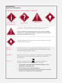
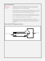
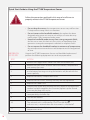
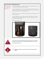
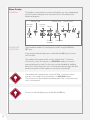
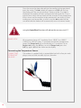
Man 239 PT100 Temperature Sensor User Manual Soil Instruments Limited has an ongoing policy of design review and reserves the right to amend these specifications without notice. Man239 - PT100 Temperature Sensor - MN0814 - Rev1.0.3 1 What’s this manual about? This manual tells you about the PT100 Temperature Sensor and how to use it to measure temperature in concrete, rock and soil. Who does this apply to? Installers, field engineers and technicians using the PT100 Temperature Sensor QUESTION 2 Welcome! Thank you for choosing the PT100 Temperature Sensor. This manual has been written to help you utilise all of the functions of the PT100 Temperature Sensor. Please read this manual thoroughly before use to help avoid any problems and keep it handy when using the PT100 Temperature Sensor. PT100 Temperature Sensor The PT100 Temperature Sensor is used to monitor temperature in concrete, rock and soil. The sensor is ideal for monitoring temperature during concrete curing, for evaluating seasonal variations within ground and structures and to interpret temperature related stress and volume changes in dams. The PT100 Temperature Sensor consists of a platinum element that changes resistance with temperature and the resulting resistance change is converted to temperature using a handheld readout or data acquisition system. The element incorporates platinum as this is a superior, chemically inert material that has the most stable resistance over the largest temperature range. This allows for a more predictable change in resistance with a higher degree of accuracy and repeatability over a far wider temperature range. PT100 Temperature Sensors provide high accuracy with low drift, making them more suitable than Vibrating Wire and Thermocouple sensors for precision applications. 3 Contents PART I – OVERVIEW6 Introduction:7 Important Information7 Product7 Changes7 Warranty7 Disposal7 System Description8 Things You Need to Know About the PT100 Temperature Sensor 8 Features8 Benefits8 System Components9 The PT100 Temperature Sensor9 Details of the PT100 Temperature Sensor 9 Quick Start Guide to Using the PT100 Temperature Sensor 10 Before You Go to Site:10 When You Are in the Field: 11 PART II –DETAILED PT100 TEMPERATURE SENSOR USER GUIDE 12 Operating the Handheld Readout 13 Installing the Batteries into the Handheld Readout 13 Menu Display14 Overview14 On and Off Functions14 Max/Min Recorder15 Open Circuit 15 Out of Range15 Display Hold15 Setting the Temperature Unit15 Speedread Function15 Range Lock16 Connecting the Temperature Sensor16 Connecting to Readout Via Lead 16 Connecting the Sensor to a Datalogger 17 4 PART III – MAINTENANCE GUIDE 18 Maintaining the PT100 Temperature Sensor 19 Cable Maintenance19 Battery Replacement19 PART IV – APPENDICES20 Appendix A - Datalogger Wiring Diagram 21 PRECISELY MEASURED instrumentation and monitoring 5 Part I – Overview Contents This section contains the following topics. TOPIC Introduction: Important Information Product Changes Warranty Disposal System Description Things You Need to Know About the PT100 Temperature Sensor Features Benefits System Components The PT100 Temperature Sensor Details of the PT100 Temperature Sensor Quick Start Guide to Using the PT100 Temperature Sensor Before You Go to Site: When You Are in the Field: 6 SEE PAGE 7 7 7 7 7 7 8 8 8 8 9 9 9 10 10 11 Introduction: Important Information The following symbols are used throughout the manual IMPORTANT INFORMATION QUESTION WARNING TIP ! Important: Failure to adhere to the warnings in this manual may result in network disruption and possible data loss. Failure to observe the warning may result in injury, product malfunction, unexpected readings or damage to the product that may invalidate its warranty. WARNING Tips give additional information that may be helpful when using a PT100 Temperature Sensor TIP PRODUCT CHANGES Soil Instruments has an on-going policy of design review and reserves the right to amend the design of their product and this instruction manual without notice. WARRANTY Refer to our terms and conditions of sale for warranty information. The batteries are a consumable item and are excluded from the warranty. DISPOSAL Products marked with the symbol are subject to the following disposal rules in European countries: • This product is designated for separate collection at an appropriate collection point • Do not dispose of as household waste • For more information, contact Soil Instruments or the local authority in charge of waste management. WEE/DE3326WV 7 System Description Things You Need to Know About the PT100 Temperature Sensor FEATURES • • • • • High accuracy and repeatability Predictable change in resistance Long-term stability over a wide temperature range Suitable for manual or remote reading and datalogging Strong, screened and flexible cable • Precise, high quality data • Reliable data that is easy to interpret • Suitable for long-term monitoring due to stable, drift free readings • Can be read with a handheld readout or automated using System Components data acquisition software, such as ‘Argus’ monitoring software • Can be used with long cable lengths (up to 600m) BENEFITS 8 System Components THE PT100 TEMPERATURE SENSOR The Soil Instruments PT100 Temperature Sensor uses a three wire configuration to minimise the effects of lead resistance, therefore providing higher accuracy and repeatability. The two leads to the sensor are attached to adjoining arms with a lead resistance in each arm of the bridge, which cancels out any resistance errors as the two lead resistances are precisely the same. The PT100 temperature sensor consists of a 100Ω platinum sensing resistor (RTD) connected to a 4 core polyurethane cable encapsulated within a 10mm diameter Stainless Steel housing. The sensing element has a theoretical sensing range of -200 to +650°C however its practical range is limited by the connecting cable and housing construction, therefore our recommended range is -20 to +100°C. Details of the PT100 Temperature Sensor R1 R2 Vb Resistance element RT Lead resistance S Power supply R3 Bridge output 9 Quick Start Guide to Using the PT100 Temperature Sensor Follow the precautions outlined in this manual at all times to properly maintain the PT100 Temperature Sensor. WARNING • Do not drop the sensor; the temperature sensor may malfunction if subjected to strong shocks or vibrations • Do not immerse the handheld readout; the readout has been designed to be water resistant to rain and jets of water but may malfunction if fully immersed under water • Keep the handheld readout away from strong magnetic fields; do not use or store this device in the vicinity of equipment that generates strong electromagnetic radiation or magnetic fields • Do not expose the handheld readout to extremes of temperature; do not expose to extreme hot or cold temperatures for long periods of time BEFORE YOU GO TO SITE: STEP ACTION 1 Remove the rugged outer rubber case from the readout unit 2 3 Remove the two screws at either side of the battery compartment and remove the cover Insert two AA batteries into the readout following the instructions on the battery housing, ensuring the batteries are placed with the correct polarity 4 Replace the battery compartment cover 5 Replace the two screws, making sure they are fully tightened 6 Replace the rubber case 7 8 9 10 11 10 Unpack the PT100 Temperature Sensor and handheld readout and perform the following equipment test and setup procedure. Carefully line up the four pin plug with the socket on the top of the readout and push together; once inserted, tighten up the thumb screw on the plug until secure Connect the pre-prepared wires from the temperature sensor to the corresponding crocodile clips Turn on the readout Select the desired temperature units by pressing the key. The selected unit is confirmed by °C or °F on the display and once set, is retained when the instrument is switched off Check the readout is displaying a stable reading for the temperature sensor Ensure the screws holding the battery compartment are securely tightened when inserting or changing the batteries to maintain the waterproof rating. WARNING WHEN YOU ARE IN THE FIELD: Soil Instruments recommend a basic skill level for using the PT100 Temperature Sensor. STEP ACTION 1 Place the PT100 Temperature Sensor into the medium to be monitored 3 Connect the pre-prepared wires from the temperature sensor to the corresponding crocodile clips Turn on the readout 4 Check and record the reading displayed on the readout 5 Wire the senor into a datalogger if using an automated system 2 The readout will automatically switch off after 12 minutes unless any key is activated or the instrument is in MAX/MIN mode. This function can be disabled by holding down the ¯ key when the unit is switched on TIP Please refer to Part IV –Appendix A – Datalogger Wiring Diagram in this manual for more details. 11 Part II – Detailed PT100 Temperature Sensor User Guide Contents This section contains the following topics. TOPIC Operating the Handheld Readout Installing the Batteries into the Handheld Readout Menu Display Overview On and Off Functions Max/Min Recorder Open Circuit Out of Range Display Hold Setting the Temperature Unit Speedread Function Range Lock Connecting the Temperature Sensor Connecting to Readout Via Lead Connecting the Sensor to a Datalogger 12 SEE PAGE 13 13 14 14 14 15 15 15 15 15 15 16 16 16 17 Operating the Handheld Readout INSTALLING THE BATTERIES INTO THE HANDHELD READOUT The handheld readout is supplied with a rubber rugged case (IP65/67) with a belt clip attached to the underside. To install the batteries you must first remove the rubber case from the readout. Once the case is removed, you will find instructions for correct battery polarity on the back of the readout. Remove the two screws at either side of the battery compartment and remove the cover. Insert the batteries ensuring they are fitted with the correct polarity before replacing the cover. Replace the screws and tighten securely to maintain waterproofing. Replace the rubber case. Ensure the screws holding the battery compartment are securely tightened when inserting or changing the batteries to maintain the waterproof rating. WARNING If the symbol appears on the display, replace the batteries. IMPORTANT INFORMATION 13 Menu Display OVERVIEW The display screen presents a variety of options via icons, depending on the function selected; a full icon overview is illustrated in the following diagram. Multifunction Multifunction Time Log HH:MM Numeric Entry Battery Yes Range Fast Celsius Channel Selection ON AND OFF FUNCTIONS Multifunction N S Cal Enter Fahrenheit The handheld readout is switched on and off using the ON and OFF keys. If you require the backlight, press and hold the ON key to activate this function. The readout will automatically switch itself off after 12 minutes of inactivity, unless the device is in MAX/MIN mode, or any key is pressed during this time. This function can be disabled by holding down the ¯ key when the unit is switched on; the function will then be de-activated until the readout is manually switched off. The readout will automatically switch off after 12 minutes unless any key is activated or the instrument is in MAX/MIN mode. This function can be disabled by holding down the ¯ key when the unit is switched on. TIP To turn on the backlight, press and hold the ON key. TIP 14 MAX/MIN RECORDER The MAX/MIN recorder stores the maximum and minimum temperature readings. To start MAX/MIN recorder, press the ¯ key. The readout will display alternating ˄˅ symbols and the current reading. Press the ¯ key again to display the maximum temperature reading; the ˄ symbol will be displayed. Press the ¯ key again to display the minimum temperature reading; the ˅ symbol will be displayed. To reset the MAX/MIN recorder function switch the readout off. Some functions may be unavailable when information is stored in MAX/MIN mode to prevent the parameters mixing whilst recording. WARNING OPEN CIRCUIT If the sensor is not properly connected, the readout will display O-C for open circuit until the problem is resolved. if the readout is in MAX/MIN mode, O-C will continue to be displayed, even after the open circuit has been cleared. WARNING OUT OF RANGE If the sensor is out of range, the readout will display OUT. DISPLAY HOLD The ¯ key will hold the display and prevent any changes. When activated, the ¯ symbol will appear on the display, press the ¯ again to return to the normal display. SETTING THE TEMPERATURE UNIT The readout has the option of displaying readings in °C (Centigrade) or °F (Fahrenheit). The desired unit is set by pressing the key. When the required unit is selected, the display will show °C or °F, respectively and the setting will be retained. SPEEDREAD FUNCTION The SpeedRead function can be used to measure poor thermal conductivity items as it enables an indicative reading within 14 seconds; however, using this function will reduce the accuracy to ±2°C. To correctly use the SpeedRead method, the sensor must be in good thermal contact with the medium to be measured, prior to activating the SpeedRead function. The difference between the initial sensor temperature and the medium under test is first required using a steep temperature gradient. 15 Once the sensor has been placed into the medium to be monitored, press the >> key. The symbol will appear and FASt will flash on the display until the correct reading is shown and the ¯ symbol is displayed. The reading will then automatically hold until the ¯ key is pressed, after which normal mode will be resumed. If the temperature of the sensor and the medium to be monitored is too similar, a faster reading may not be possible, in which case the symbol will be cancelled and the readout will automatically return to normal mode. using the SpeedRead function will reduce the accuracy to ±2°C. WARNING RANGE LOCK All instruments have a 0.1° resolution from -199.9°C to +199.9°C (-199.9°F to +392.8°F) and a 1° resolution outside this temperature range. The Range Lock will set the display to 1° resolution. To set Range Lock, press the A/R key, to cancel Range Lock, press the A/R key again; A/R will be shown on the display. Connecting the Temperature Sensor CONNECTING TO READOUT VIA LEAD 16 The readout is supplied with an expandable lead with a four pin male plug at one end and crocodile clips on the other. Carefully line up the four pin plug with the socket on the top of the readout and push together; once inserted, tighten up the thumb screw on the plug until secure tightened. Ensure the four pin plug and socket connection are properly aligned before pushing together to avoid damage to the connector pins. WARNING If the symbol appears on the display, replace the batteries. IMPORTANT INFORMATION To turn on the backlight, press and hold the ON key. TIP CONNECTING THE SENSOR TO A DATALOGGER There are three ways to connect the sensor to a datalogger depending on the cable length and the precision required. You can find the three options and wiring for each in Appendix A. Please refer to Part IV –Appendix A – Datalogger Wiring Diagram in this manual for more details. 17 Part III – Maintenance Guide Contents This section contains the following topics. TOPIC Maintaining contents the PT100 Temperature Sensor Cable Maintenance Battery Replacement TOPIC Introduction Important Information System Description Things you need to know about the MAlog System Components Quick Guide to using the MAlog 18 SEE PAGE 19 19 19 SEE PAGE 8 8 9 9 9 10 Maintaining the PT100 Temperature Sensor Follow the precautions outlined in this manual at all times to properly maintain the PT100 Temperature Sensor. WARNING CABLE MAINTENANCE The PT100 Temperature is a sensitive piece of equipment and must be handled with care; ensure that you adhere to the following precautions when handling the instrument to maintain full working order: • Do not drop the sensor; the temperature sensor may malfunction if subjected to strong shocks or vibrations • Do not immerse the handheld readout; the readout has been designed to be water resistant to rain and jets of water but may malfunction if fully immersed under water • Keep the handheld readout away from strong magnetic fields; do not use or store this device in the vicinity of equipment that generates strong electromagnetic radiation or magnetic fields • Do not expose the handheld readout to extremes of temperature; do not expose to extreme hot or cold temperatures for long periods of time BATTERY REPLACEMENT The symbol on the readout display indicates that the battery levels are low and the batteries need replacing. The readout requires two AA batteries. STEP 1 ACTION Remove the waterproof outer rubber case from the readout unit 2 Remove the two screws at either side of the battery compartment and remove the cover 3 Insert two AA batteries into the readout following the instructions on the battery housing, ensuring the batteries are placed with the correct polarity 4 5 6 Replace the battery compartment cover Replace the two screws, making sure they are fully tightened Replace the rubber case 19 Part IV – Appendices Contents This section contains the following topics. TOPIC Appendix A - Datalogger Wiring Diagram 20 SEE PAGE 21 Appendix A - Datalogger Wiring Diagram LOWER PRECISION Lower Precision Measurements (or short cable length) Datalogger Wiring Red + White = SE Black + Green = Excitation (Ex) Current limiting 10kΩ resistor: Tolerance @25°C: ±5% Power rating: 0.25W 10k Completion resistor: Tolerance @25°C: ±0.01% Single Ended (SE) PT100 Ground ( HIGH PRECISION Temperature coefficient: 0 - +60°C: 4 ppm/°C -55 - +125°C: 8 ppm/°C Power rating: 0.25W ) High Precision Measurements (or medium to long cable length) Datalogger Wiring Red = H White = L Black = Excitation (Ex) Current limiting 10kΩ resistor: Tolerance @25°C: ±5% Power rating: 0.25W 10k Completion resistor: Tolerance @25°C: ±0.01% Single Ended H L PT100 Temperature coefficient: 0 - +60°C: 4 ppm/°C -55 - +125°C: 8 ppm/°C Power rating: 0.25W 21 VERY HIGH PRECISION Very High Precision Measurements (or very long cable length) Datalogger Wiring Red = L1 White = H2 Green = L2 Black = Excitation Vx Current limiting 10kΩ resistor: Tolerance @25°C: ±5% Power rating: 0.25W 10k H1 Completion resistor: Tolerance @25°C: ±0.01% 100Ω L1 H2 PT100 L2 22 Temperature coefficient: 0 - +60°C: 4 ppm/°C -55 - +125°C: 8 ppm/°C Power rating: 0.25W SUPPORT www.itmsoilsupport.com +44 (0) 1825 765044 23 Bell Lane, Uckfield, East Sussex TN22 1QL United Kingdom t: f: +44 (0) 1825 765044 +44 (0) 1825 744398 e: [email protected] w: www.itmsoil.com Soil Instruments Ltd. Registered in England. Number: 07960087. Registered Office: 5th Floor, 24 Old Bond Street, London, W1S 4AW 24