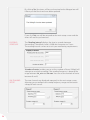
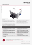
1
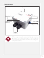
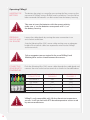
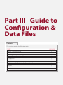
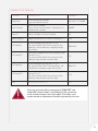
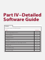
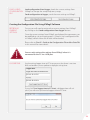
Man 235
VWlog2
User Manual
Soil Instruments Limited has an ongoing policy of design review and reserves the right to amend these specifications without notice.
Man235 - VWlog2 - MN0814 - Rev1.0.0.
1
What’s this manual about? This manual tells you about the two channel VWlog2 and
how to use it to take readings.
Who does this apply to?
Installers, field engineers and technicians who need to install,
commission and maintain a VWlog2 system.
QUESTION
2
Welcome!
Thank you for choosing VWlog2.
This manual has been written to help you utilise all of the
functions of VWlog2. Please read this manual thoroughly
before use to help avoid any problems and keep it handy
when using VWlog2.
VWlog2
VWlog2 is a two channel Datalogger, which reads and logs
most commercially available Vibrating Wire (VW) sensors
and optional thermistor temperature sensors. Data is stored
as a CSV file onto the internal memory.
The VWlog2 contains 4MB of non-volatile internal memory
which is sufficient for up to 50,000 readings per channel,
equating to 5.7 years of data sampling at hourly intervals.
The internal memory in VWlog2 operates as a USB mass
storage device, which is accessible through a mini USB
interface, allowing data to be easily transferred from VWlog2
to a PC or mobile device via drag-and-drop, using the same
action as a file on the PC’s hard drive.
The included VWlog2 software enables the user to easily setup
the VWlog2 parameters, such as date and time, sweep frequency
range and excitation voltage.
VWlog2 is housed in a waterproof, rugged, die-cast aluminium
enclosure, providing a rating of IP68 and all electronics are
encased in an impervious sealing compound to avoid
water damage.
With these features, VWlog2 is ideal for long-term and
remote monitoring projects including those in harsh
or damp environments.
3
Contents
PART I – OVERVIEW6
Introduction:7
Important information7
Product7
Changes7
Warranty7
Disposal7
System Description8
Things You Need to Know About VWlog2
8
Features8
Benefits8
System Components8
The VWlog28
Quick Start Guide 10
Before You Go to Site:
10
When You Are in the Field:
10
When You Need to Collect Data:
10
PART II – DETAILED VWLOG2 USER GUIDE
11
Operating VWlog2 12
Inserting the Batteries12
Preparing VWlog2 and VW Sensors 12
Connecting Sensors with Temperature
12
Connecting Sensors without Temperature
13
LED Sequence 13
PART III – GUIDE TO CONFIGURATION & DATA FILES
14
VWlog2 Configuration File15
Overview15
VWlog2 Configuration File15
Format of the Configuration File
16
Properties16
Sections16
Line Terminators, Spaces and Comments
17
Contents of Configuration File (“xxxxvwl.cfg”)
17
Data File17
Overview17
Format of the Data File
19
4
PART IV – DETAILED SOFTWARE GUIDE
20
VWlog2 Software21
Connecting VWlog2 to Your PC
21
Software Overview21
Software Functions22
Logger Time22
Logging Schedule22
Channel 1 22
Channel 2 22
Load & Send Configuration File
23
Creating the Configuration File Using VWlog2 Software
23
Retrieving Current Settings23
Logger Time23
Logging Schedule24
VW Channel Setup24
Sweep Frequency Range25
Excitation Voltage25
PART V – MAINTENANCE GUIDE
26
Maintaining the VWlog2 System
27
Routine Maintenance27
Battery Maintenance27
PART VI - APPENDICES28
Appendix A - Firmware Update
29
Appendix B – Frequently Asked Questions
30
PRECISELY MEASURED
instrumentation and monitoring
5
Part I – Overview
Contents
This section contains the following topics.
TOPIC
Introduction:
Important information
Product
Changes
Warranty
Disposal
System Description
Things You Need to Know About VWlog2
Features
Benefits
System Components
The VWlog2
Quick Start Guide Before You Go to Site:
When You Are in the Field:
When You Need to Collect Data:
6
SEE PAGE
7
7
7
7
7
7
8
8
8
8
8
8
10
10
10
10
Introduction:
Important information
The following symbols are used throughout the manual
IMPORTANT
INFORMATION
QUESTION
WARNING
TIP
! Important: Failure to adhere to the warnings in this manual
may result in network disruption and possible data loss.
Failure to observe the warning may result in injury, product
malfunction, unexpected readings or damage to the product
that may invalidate its warranty.
WARNING
Tips give additional information that may be helpful when
using VWlog2.
TIP
PRODUCT
CHANGES
Soil Instruments has an on-going policy of design review and
reserves the right to amend the design of their product and
this instruction manual without notice.
WARRANTY
Refer to our terms and conditions of sale for warranty information.
The batteries are a consumable item and are excluded from
the warranty.
DISPOSAL
Products marked with the symbol are subject to
the following disposal rules in European countries:
• This product is designated for separate collection at an
appropriate collection point
• Do not dispose of as household waste
• For more information, contact Soil Instruments or the local
authority in charge of waste management.
WEE/DE3326WV
7
System Description
Things You Need to Know About VWlog2
FEATURES
• Reads two Vibrating Wire (VW) sensors and optional thermistor
temperature sensors
• 4 MB internal memory; reads up to 50,000 readings per channel,
equating to five years of data sampling at hourly intervals
• IP68 rated, rugged, die-cast aluminium enclosure
• Low power requirement; 2 x D Cell batteries last up to two years
• Easy configuration and firmware upgrade via mini-USB to
USB cable
• True USB interface; data downloaded via drag-and-drop
• Reads any user definable frequency sweep range between
1700 to 6000 Hz.
BENEFITS
• Reads most types of commercially available Vibrating Wire
(VW) sensors
• Optional 15V excitation ensures quality readings from sensors
with long cables
• Ideal for long-term monitoring in harsh and damp environments
• Allows data collection immediately after sensor installation
• Fast setup and download time
• Versatile and economical
• All electronics sealed to protect from static and water damage.
System Components
THE VWLOG2
The VWlog2 is a rugged two channel Datalogger that will energise and
read up to two Vibrating Wire (VW) sensors and optional thermistor
temperature sensors and then store the readings internally for retrieval
via a mini-USB to USB cable.
All settings are stored in a configuration file that is uploaded to VWlog2
via a mini-USB to USB cable. Once uploaded, these settings are saved
internally and will be used until a new configuration file is uploaded.
8
Details of VWlog2
Top cover
Channel number
indicator (1)
USB indicator
Channel number
indicator (2)
Serial number
USB protective cap
Cable glands
Soil Instruments recommends carrying out a functionality test before
going to site. After installing the software and sending the configuration
file to VWlog2, wire in a Vibrating Wire (VW) sensor and allow VWlog2 to
take several readings. Download the data and check the readings and
configurations are correct.
TIP
9
Quick Start Guide
Take care to insert the batteries with the correct polarity;
make sure +/- on the batteries corresponds with +/- on
the battery housing.
WARNING
BEFORE YOU
GO TO SITE:
• Remove the top cover of VWlog2 using a Phillips head screwdriver
• Insert 2 good quality, 1.5V Alkaline D Cell batteries into VWlog2
battery housing
• Install Soil Instruments VWlog2 software provided on disc
• Connect VWlog2 to your PC or laptop using the mini-USB to
USB cable
• Create the configuration file using VWlog2 software
• Send the configuration file to VWlog2
• Unplug the USB cable and replace the protective cap
• Replace the top cover.
VWlog2 has no on/off switch. It will start reading and storing data
as soon as the batteries are inserted.
IMPORTANT
WHEN
YOU
• Remove the top cover of VWlog2 using a Phillips head screwdriver
INFORMATION
ARE IN THE
• Connect up to two Vibrating Wire (VW) sensors (each can be with
FIELD:
an optional built-in thermistor temperature sensor) to the wiring
terminals in VWlog2
• Insert 2 x D Cell batteries into VWlog2 battery housing
• Replace the top cover
• Leave VWlog2 in a non-submerged and safe location.
WHEN YOU
NEED TO
COLLECT DATA:
• Connect VWlog2 to your PC or laptop using the mini-USB to
USB cable
• Use drag-and-drop to transfer the data file to your PC or laptop
• View the data in a spreadsheet or text editor.
If using a text editor, Soil Insruments recommends ‘NotePad++’
because it will display the lines in a more organised fashion using
a column format.
TIP
10
Please refer to ‘Part II – Detailed VWlog2 User Guide’ in this manual for
more details.
Part II –
Detailed VWlog2
User Guide
Contents
This section contains the following topics.
TOPIC
Operating VWlog2 Inserting the Batteries
Preparing VWlog2 and VW Sensors
Connecting Sensors with Temperature
Connecting Sensors without Temperature
LED Sequence SEE PAGE
12
12
12
12
13
13
11
Operating VWlog2
INSERTING THE
BATTERIES
The battery housing is accessed by unscrewing the four screws on the
top cover of VWlog2 using a Phillips head screwdriver. Once the lid has
been removed the batteries can be inserted into the battery housing.
Take care to insert the batteries with the correct polarity;
make sure +/- on the batteries corresponds with +/- on
the battery housing.
WARNING
PREPARING
VWLOG2 AND
VW SENSORS
Loosen the cable glands by turning the outer connection in an
anti-clockwise direction.
Strip the Vibrating Wire (VW) sensor cable, making sure an adequate
length of the internal cables are exposed to wire into the VWlog2
sensor terminals.
Only a competent person trained in the use of VWlog2 and
Vibrating Wire sensors should connect the sensors.
WARNING
CONNECTING
SENSORS WITH
TEMPERATURE
Push the Vibrating Wire (VW) sensor cable through the cable gland and
connect the wires to the sensor terminals as shown in the table below.
SENSOR
CONNECTIONS
VW Sensor +
SENSOR TERMINAL:
CHANNEL 1
VW1
SENSOR TERMINAL:
CHANNEL 2
VW2
VW Sensor -
VW1
VW2
VW Thermistor +
Tmp1
Tmp2
VW Thermistor -
Tmp1
Tmp2
Shield
Shld
Shld
VWlog2 is only compatible with 3 K ohm thermistor temperature
sensors. It will not work with RTD-based temperature sensors used
by some manufacturers.
WARNING
12
CONNECTING
SENSORS
WITHOUT
TEMPERATURE
Push the Vibrating Wire (VW) sensor cable through the cable gland
and connect the wires to the sensor terminals as shown in the
following table.
SENSOR
CONNECTIONS
VW Sensor +
SENSOR TERMINAL:
CHANNEL 1
VW1
SENSOR TERMINAL:
CHANNEL 2
VW2
VW Sensor -
VW1
VW2
Not used
Tmp1
Tmp2
Not used
Tmp1
Tmp2
Shield
Shld
Shld
Once Vibrating Wire sensors have been connected to VWlog2,
ensure the cable glands are thoroughly tightened to maintain
a watertight seal.
WARNING
LED SEQUENCE
LED SEQUENCE
Once the VWlog2 has been installed and the batteries inserted, the
following LED sequence will occur, informing you of the logger status.
DESCRIPTION
Batteries inserted, Logger
functioning
LOGGER STATUS LED
‘Heartbeat’ – flashing every 7
seconds
2
Logger taking a reading
Solid red light (based on reading
interval)
3
Logger connected to PC
Solid red light
1
Your Logger is now ready to use.
Please proceed to the following sections;
‘Part III – Guide to Configuration & Data Files’ and
‘Part IV – Detailed Software Guide’ in this manual for details on
how to configure the logger and use the software to retrieve data.
13
Part III – Guide to
Configuration &
Data Files
Contents
This section contains the following topics.
TOPIC
VWlog2 Configuration File
Overview
VWlog2 Configuration File
Format of the Configuration File
Properties
Sections
Line Terminators, Spaces and Comments
Contents of Configuration File (“xxxxvwl.cfg”)
Data File
Overview
Format of the Data File
14
SEE PAGE
15
15
15
16
16
16
17
17
17
17
19
VWlog2 Configuration File
OVERVIEW
The VWlog2 configuration file holds information on how and when the
Vibrating Wire (VW) sensors are read.
The configurable parameters within the VWlog2 configuration file are
as follows;
• Reading interval
• Timer start (not currently used, reserved for future use)
• Timer end (not currently used, reserved for future use)
• Number of retries
• Sweep frequency range
• Excitation voltage.
The sweep frequency range and excitation voltage can be individually
modified for both channels.
The configuration file is retrieved from VWlog2 and modified using Soil
Instruments VWlog2 software. Once the settings have been modified to
suit your requirements, the new configuration file is sent back to VWlog2.
VWlog2 will use the new settings on the next data cycle.
Please refer to ‘Part IV – Detailed Software Guide‘ in this manual for
more details.
VWLOG2
CONFIGURATION
FILE
The VWlog2 configuration file is a text file that holds information on
how the Vibrating Wire (VW) sensors are read.
The filename is “xxxx.cfg”, where; “xxxx“ is the VWlog2 ID
(four character serial number found on the silver label).
More details on the content and format of “xxxx.cfg” are shown in the
following table.
On power up, VWlog2 reads the information in “xxxx.cfg” and uses this
information to read the sensors and save the data to its memory.
SECTION
AVAILABLE
PROPERTIES
VALID
VALUE
[Schedule] Reading_Interval 30 to 3600
DESCRIPTION
RECOMMENDED
VALUE
Time (in seconds)
3600
between the readings
Timer_start
0...23:00...59
Not currently used,
00:00
reserved for future use
Timer_end
0...23:00...59
Not currently used,
00.00
reserved for future use
15
SECTION
AVAILABLE
PROPERTIES
VALID
VALUE
DESCRIPTION
RECOMMENDED
VALUE
0 to 5
Number of times to re-take
the reading if the reading
frequency is beyond the
range between Hz_min
and Hz-max
3
[Channel1] Hz_min
1700 - 6000
(integer)
Swept freq min in Hz
>=1700
Hz_max
1700 - 6000
(integer)
Swept freq max in Hz
>=6000
Excitation_
Voltage
5 to 15
Excitation voltage in V
5
[Channel2] Hz_min
1700 - 6000
(integer)
Swept freq min in Hz
>=1700
Hz_max
1700 - 6000
(integer)
Swept freq max in Hz
>=6000
Excitation_
Voltage
5 to 15
Excitation voltage in V
5
[Schedule]
Num_Retry
Format of the Configuration File
PROPERTIES
The basic element contained in a CFG file is the property.
Every property has a name and a value, delimited by an equals sign (=).
The name appears to the left of the equals sign.
name=value
The text value must be quoted by using double quotes;
name=”value”
The property names are not case sensitive and cannot contain space
between characters. If a property is skipped or is not included in the
configuration file, the default values of this property will be assumed.
SECTIONS
Properties have been grouped into sections. The section name appears
on a line by itself, in square brackets ( [ and ] ). All properties after the
section declaration are associated with that section. There is no explicit
“end of section” delimiter; sections end at the next section declaration,
or the end of the file. Sections may not be nested.
[section]
The section names are not case sensitive and cannot contain space
between characters. If the same section appears more than once in
the same file, or if the same property name appears more than once
in the same section, then the last occurrence prevails.
16
If there is an unrecognised section name, the entire section (with all its
properties) will be skipped. Within a known section, all unrecognised
properties will be skipped.
If a section is skipped, or is not included in the Logger Configuration File,
the default values of all the properties in the section will be assumed.
LINE
TERMINATORS,
SPACES AND
COMMENTS
Lines are terminated by a CR+LF (carriage return + line feed).
Semicolons (;) at the beginning of the line indicate a comment.
; comment text
Comments, empty lines and spaces at the beginning of a line will
be ignored.
The name of the configuration file is “xxxx.cfg”, where; “xxxx” is the
VWlog2 ID (four character serial number found on the silver label).
CONTENTS OF
An example of the VWlog2 configuration file is shown below;
CONFIGURATION
FILE
; VVlog2_V1
(“XXXXVWL.CFG”)
; Config file
; 15 August 2014
; Author: Soil Instruments
;
[Schedule]
Reading_Interval=3600
Timer_start=00:00 (not currently used, reserved for future use)
Timer_end=00:00 (not currently used, reserved for future use)
Num_Retry=0
[Channel1]
; The external channel #1 - VW Rod-Ex
Hz_min=1700
Hz_max=3400
Excitation_Voltage=5
[Channel2]
; The external channel #2 - VW Rod-Ex
Hz_min=1700
Hz_max=3400
Excitation_Voltage=15
Data File
OVERVIEW
The data file is transferred from VWlog2 to your PC or laptop via
drag-and-drop and can be viewed via a spreadsheet or in a text
editor on your PC.
17
If using a text editor, we recommend ‘NotePad++’ because it will
display the lines in a more organised fashion using a column format.
TIP
Once connected, VWlog2 appears as a removable storage device on
your PC or laptop as shown below.
When you open VWlog2, two data files are displayed; a text document
and a CSV file. The files may be transferred to your PC or laptop by
dragging-and-dropping.
The CSV file can be opened in ‘Excel’.
TIP
Example of a data file
18
FORMAT OF THE DATA FILE
COLUMN
DESCRIPTION
EXAMPLE
Date/Time
Date and time of reading
(yyyy-mm-dd hh:mm:ss)
2013-02-13 17:30:00
Serial Number
Sensor serial number.
There sensor serial number is displayed as a
hexadecimal number
0x000A
Vbatt(V)
Battery voltage at time of reading
3.0
Board Temp(°C)
Logger temperature at time of readings in °C
22.8
Sensor reading from channel 1 in Hz.
The value will be “NAN” if no sensor or the
reading is still outside the sweeping range
after retries
3059.669
Thermistor temperature sensor reading from
channel 1 in °C.
The value will be “NAN” if no sensor or the
reading is beyond the normal range
21.1
Sensor reading from channel 2 in Hz.
The value will be “NAN” if the reading is still
outside the sweeping range after retries
3088.827
Thermistor temperature sensor reading from
channel 2 in °C.
The value will be “NAN” if no sensor or the
reading is beyond the normal range
21.4
Reserved for future use
N/A
CH1 freq(Hz)
CH1 temp(°C)
CH2 freq(Hz)
CH2 temp(°C)
Flags
There are two other files to be aware of, “TIME.TXT” and
“xxxx.LOG” (where “xxxx” is the VWlog2 ID four character
serial number found on the silver label). These files must
not be moved or deleted and should be ignored by the user.
WARNING
19
Part IV – Detailed
Software Guide
Contents
This section contains the following topics.
TOPIC
VWlog2 Software
Connecting VWlog2 to Your PC
Software Overview
Software Functions
Logger Time
Logging Schedule
Channel 1
Channel 2
Load & Send Configuration File
Creating the Configuration File Using VWlog2 Software
Retrieving Current Settings
Logger Time
Logging Schedule
VW Channel Setup
Sweep Frequency Range
Excitation Voltage
20
SEE PAGE
21
21
21
22
22
22
22
22
23
23
23
23
24
24
25
25
VWlog2 Software
CONNECTING
VWLOG2 TO
YOUR PC
Connect VWlog2 to your PC or laptop using the mini-USB to USB cable.
The mini-USB port on VWlog2 is housed within a protective, watertight
cap which can be found on the right hand side of the unit.
When the VWlog2 is connected to your PC, a solid red light will be visible
next to the USB input.
Once connected, VWlog2 appears as a removable storage device on your
PC or laptop.
If VWlog2 is scheduled to read a sensor, the USB connection will
be temporarily disrupted while the reading is taken. This ensures
that no data is missed during connection. Once data has been
successfully recorded, the USB connection will be re-established.
IMPORTANT
SOFTWARE
INFORMATION
OVERVIEW
Soil Instruments VWlog2 software helps you to modify the logger
configuration file.
The name of the configuration file is “xxxx.cfg”, where; “xxxx” is the
VWlog2 ID (four character serial number found on the silver label).
When you start the software you will be presented with the setup screen.
The software version is displayed at the top of the form after the software
name as shown in the screen shot below.
21
Software Functions
LOGGER TIME
Logger time when connected to PC; displays the date and time
from VWlog2 when it is connected to your PC.
PC time; displays the date and time from your PC. This will be
updated automatically.
Sync logger time to PC time; synchronises the time from VWlog2
to the time from your PC.
LOGGING
SCHEDULE
Reading Interval (seconds); the time (in seconds) between
the readings.
Timer starts at (hh:mm); not currently used, reserved for future use.
Timer ends at (hh:mm); not currently used, reserved for future use.
Number of retries; the number of times VWlog2 will attempt to take
readings if the measured reading is outside the set sweep frequency.
CHANNEL 1
Sweep frequency range; allows you to select the Start Hz and
End Hz sweep frequency range for channel 1.
Excitation Voltage; allows you to select the excitation voltage
for channel 1 (5 or 15 V).
CHANNEL 2
Sweep frequency range; allows you to select the Start Hz and
End Hz sweep frequency range for channel 1.
Excitation Voltage; allows you to select the excitation voltage
for channel 2 (5 or 15 V).
22
LOAD & SEND
Load configuration from logger; loads the current settings from
CONFIGURATION VWlog2 to change the sweep frequency range.
FILE
Send configuration to logger; sends the new settings to VWlog2.
Creating the Configuration File Using VWlog2 Software
RETRIEVING
CURRENT
SETTINGS
To start, you will need to retrieve the current settings from VWlog2
by clicking on the ‘Load configuration from logger’ button.
Once the current settings from VWlog2 are displayed, the parameters can
be modified to suit your requirements. If there is not a configuration file
in VWlog2, default values for all fields will be loaded.
Please refer to ‘Part III – Guide to the Configuration File and the Data File’
in this manual for more details.
You can only retrieve the settings from VWlog2 when it is
connected to the PC via a USB port.
WARNING
LOGGER TIME
Synchronising logger time to PC time ensures that there is no time
drift and enables you to update to daylight saving time.
If you click ‘Sync logger time to PC time’, a dialogue box will ask
you if you want to synchronise logger time to PC time.
23
By clicking ‘Yes’, the times will be synchronised and a dialogue box will
inform you that the times have been updated.
If you click ‘No’, you will be returned to the main setup screen and the
times will not be synchronised.
LOGGING
SCHEDULE
The ‘Reading Interval’ displays the time in seconds between
the readings. The default value is 3600 which equates to 1 hour.
The reading interval can be set to suit your monitoring requirements.
‘Number of retries’ enables you to set the number of times VWlog2 will
attempt to re-take the reading if the reading frequency is beyond the
range between Hz_min and Hz-max. You can set the number of retries
between 0 and 5.
VW CHANNEL
SETUP
24
The two channels are displayed separately in the main setup screen,
allowing you to configure the sweep frequency range and excitation
voltage of each sensor.
SWEEP
FREQUENCY
RANGE
To change the sweep frequency range you can either click on the boxes
of ‘Start (Hz)’ and ‘End (Hz)‘ or click the ‘....’ button. This will open a new
window where you can select one of the pre-defined sweep ranges or
you can type in custom ‘Start Frequency‘ and ‘End Frequency’. Once
you have selected the sweep range, click ‘Apply‘ to save the settings.
Reserved for future use.
Reserved for future use.
Soil Instruments recommend you consult the manufacturers’
manual for the recommended sweep frequency range for the
particular instrument being used.
IMPORTANT
INFORMATION
A narrower sweep band will produce a better quality signal.
TIP
EXCITATION
VOLTAGE
You can select the 15 V DC excitation option if the sensor has a
long cable. As a guide, a cable is considered long if it is over 200m
(600 ft), however, Soil Instruments advise that you consult the
manufacturers’ manual for the recommended excitation voltage
for the particular instrument being used.
25
Part V –
Maintenance
Guide
Contents
This section contains the following topics.
TOPIC
Maintaining the VWlog2 System
Routine Maintenance
Battery Maintenance
26
SEE PAGE
27
27
27
Maintaining the VWlog2 System
ROUTINE
MAINTENANCE
VWlog2 is manufactured with multilayer circuit boards containing
surface mounted components. For this reason there are no parts
which require routine maintenance other than the replacement
of the batteries and recalibration of VWlog2.
Ensure the protective cap of the USB port and cable glands
are securely tightened so that VWlog2 remains watertight.
WARNING
BATTERY
MAINTENANCE
VWlog2 is powered by 2 x D Cell batteries. VWlog2 battery status can
be logged at regular intervals to monitor the battery levels, avoiding
loss of power and therefore loss of data by making sure you replace
the batteries in a timely manner.
When replacing the batteries, make sure you run all the start-up tests
to confirm that VWlog2 is fully functioning.
Take care to insert the batteries with the correct polarity;
make sure +/- on the batteries corresponds with +/- on
the battery housing.
WARNING
Battery life is dependent on the following factors;
• Battery type/quality
• Sensor reading frequency
• Ambient temperature
Soil Instruments advise that with both channels active, two new
D Cell alkaline batteries will keep VWlog2 in operation for two
years while reading two Vibrating Wire (VW) sensors and two
temperature sensors every hour.
The minimum voltage of VWlog2 is 2V, but please be aware that
this is for VWlog2 only and not for any sensors attached to it.
Please refer to the manufacturers’ manual for your sensors for
further information.
WARNING
27
Part VI Appendices
Contents
This section contains the following topics.
TOPIC
Appendix A - Firmware Update
Appendix B – Frequently Asked Questions
28
SEE PAGE
29
30
Appendix A - Firmware Update
You can update VWlog2 firmware locally. The firmware will be supplied
by Soil Instruments as a binary file with a “hex” extension. The typical
filename is “xxxx.hex”.
To perform a firmware update:
STEP
ACTION
1
Rename the latest firmware file such as “xxxx.hex” to “image.hex”
2
Connect VWlog2 to the PC using a mini-USB to USB cable
3
Copy “image.hex” to VWlog2 memory which appears as a removable drive
4
Disconnect VWlog2 from the PC
5
VWlog2 will now be updated to the new firmware
6
VWlog2 will then delete “image.hex” from its memory
29
Appendix B – Frequently Asked Questions
Why is VWlog2 not showing as a removable drive on my PC
or laptop?
QUESTION
Firstly, make sure the mini-USB is correctly inserted into VWlog2.
When VWlog2 is connected to your PC, a solid red light should be
displayed to the right of the USB port. If the mini-USB to USB cable
is correctly inserted but there is still no red light, you may have a
faulty USB port on your PC. Check this by plugging into a different
USB port if one is available, alternatively try a different PC. If after
these checks VWlog2 is still not connecting, you may have a faulty
mini-USB to USB cable, in which case you can try a different cable.
If the problem still persists please contact our support team.
Why is VWlog2 not working after I have replaced
the batteries?
Check that the batteries are new and have been inserted with the
correct polarity. The problem may be caused by cable damage or a
bad connection from the battery housing to the wiring terminal.
You can check this by using a Multimeter to test the battery power.
If the batteries have full voltage but VWlog2 is still not functioning,
please contact our support team.
What sweep frequency range should I use for my Vibrating
Wire (VW) sensors?
You should avoid using VWlog2 default sweep frequency range
(1700 - 6000 Hz) because it is too wide for good quality reading using
zero-crossing method. Below is a table showing the sweep frequency
ranges for various VW sensors manufactured by Soil Instruments.
This table is a reference for Soil Instruments VW sensors only, for
non-Soil Instruments sensors please refer to the manufacturers’
recommended sweep frequency range.
Sweep Frequency Ranges for Soil Instruments Vibrating Wire Sensors
30
INSTRUMENT
CATALOGUE CODE
SIGNAL RANGE
VW Piezometer
VW Pressure Cell
VW Settlement Cell
VW Load Cell
VW Temperature Sensor
VW Weir Sensor
W4, W9
P6, P9, P10
S8
L2
T3
W10
1700 - 3400 Hz
1700 - 3400 Hz
1700 - 3400 Hz
2000 - 3000 Hz
2000 - 3500 Hz
2000 - 3500 Hz
SUPPORT
www.itmsoilsupport.co.uk
+44 (0) 1825 765044
31
Bell Lane, Uckfield, East Sussex
TN22 1QL United Kingdom
t:
f:
+44 (0) 1825 765044
+44 (0) 1825 744398
e: [email protected]
w: www.itmsoil.com
Soil Instruments Ltd. Registered in England. Number: 07960087. Registered Office: 5th Floor, 24 Old Bond Street, London, W1S 4AW
32