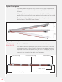
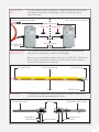
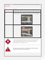
1
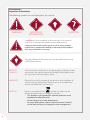
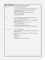
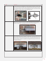
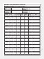
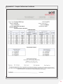
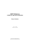
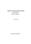
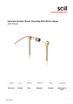
Man 246
MEMS BEAM
SENSOR
User Manual
Soil Instruments Limited has an ongoing policy of design review and reserves the right to amend these specifications without notice.
Man246 - MEMS Beam Sensor - MN1114 - Rev1.0.0
1
What’s this manual about? This manual tells you about the MEMS Beam Sensor and
how to use it to measure vertical rotations of structures.
Who does this apply to?
Installers, field engineers and technicians who need to
install and acquire readings from MEMS Beam Sensors.
2
Welcome!
Thank you for choosing the MEMS Beam Sensor.
This manual has been written to provide you with relevant
information and to guide you in the best practice for the
use and installation of a MEMS Beam Sensor in order for you
to get the most out of our product.
Please read this manual thoroughly before use to help
avoid any problems and keep it handy when installing a
MEMS Beam Sensor.
MEMS Beam Sensor
The MEMS Beam Sensor is designed to measure vertical
rotations of structures.
There are two options available for the MEMS Beam Sensor;
a Standard Beam Sensor which is an independently cabled
sensor that connects to a Datalogger or a Smart Beam Sensor
which is an inter-connecting sensor. The Sensors are available
in either aluminium or Glass Reinforced Plastic (GRP).
Both sensor types deliver a large measuring range with high
sensitivity and relative immunity from the effects of long
cable lengths and require no zero level adjustment.
Each sensor incorporates an on-board microprocessor which
performs an automatic temperature compensation of the tilt
(g) data, delivering reliable, accurate and stable data.
The data can be directly imported into our web-based
monitoring software, providing a near real time tilt data that
is constantly updated and available to view from any PC or
mobile device with an internet connection.
3
Contents
PART I – OVERVIEW6
Introduction:8
Important Information8
Product8
Changes8
Warranty8
Disposal8
System Description:9
Things You Need to Know about MEMS Beam Sensors
9
Features9
Benefits9
Applications9
System Description10
System Components10
Smart MEMS Beam Sensor 10
Connection Box11
Standard MEMS Beam Sensor
11
Anchor Kit11
PART II – MEMS BEAM SENSOR INSTALLATION GUIDE
12
Installing a MEMS Beam Sensor 14
Smart MEMS Beam Sensor Installation
15
Wiring Table19
Standard MEMS Beam Sensor Installation
19
PART III - STANDARD MEMS BEAM SENSOR WIRING &
PROGRAMMING GUIDE24
Wiring the Standard MEMS Beam Sensors
26
Overview26
Wiring Table26
Function Test27
Logger Programming27
Data Reduction28
PART V –APPENDICES30
Appendix A - Sample Installation Record Sheet
32
Appendix B – Sample Calibration Certificate
33
4
PRECISELY MEASURED
instrumentation and monitoring
5
Part I – Overview
6
Contents
This section contains the following topics.
TOPIC
Introduction:
Important Information
Product
Changes
Warranty
Disposal
System Description:
Things You Need to Know about MEMS Beam Sensors
Features
Benefits
Applications
System Description
System Components
Smart MEMS Beam Sensor
Connection Box
Standard MEMS Beam Sensor
Anchor Kit
SEE PAGE
8
8
8
8
8
8
9
9
9
9
9
10
10
10
11
11
11
7
Introduction:
Important Information
The following symbols are used throughout this manual
WARNING
IMPORTANT
INFORMATION
TIP
QUESTION
! Important: Failure to adhere to the warnings in this manual
may result in network disruption and possible data loss.
Failure to observe the warning may result in injury, product
malfunction, unexpected readings or damage to the product
that may invalidate its warranty.
Tips give additional information that may be helpful when using
a MEMS Beam Sensor.
8
PRODUCT
CHANGES
Soil Instruments Limited has an on-going policy of design review
and reserves the right to amend the design of their product and
this instruction manual without notice.
WARRANTY
Please refer to Soil Instruments Limited terms and conditions of
sale for warranty information. Batteries are a consumable item
and are excluded from any warranty.
DISPOSAL
Products marked with the symbol are subject to the
following disposal rules in European countries:
• This product is designated for separate collection at an
appropriate collection point
• Do not dispose of as household waste
• For more information, contact Soil Instruments Limited
or the local authority in charge of waste management.
System Description:
Things You Need to Know about MEMS Beam Sensors
FEATURES
• Inter-connecting Smart Sensors
• Accurate and precise measurements using MEMS sensors
• Multiple beams installed in a chain give a complete
displacement profile
• Measures tilt along the whole length of the beam
• Measures vertical rotation
• Large measuring range.
BENEFITS
• Fast onsite installation with minimal cable management;
reduces cable and Datalogger costs
• Easy to automate using data acquisition system and ‘ARGUS’
monitoring software
• Removes the need for manual monitoring
• Recoverable and reusable
• Suitable for safety critical applications
• Fast onsite installation; no zero level adjustment required.
APPLICATIONS
•
•
•
•
•
•
•
•
Brick and stone buildings
Heave and settlement due to adjacent construction activities
Bridges and dams
Impounding and loading effects in the short or long-term
Pipelines
Differential levels
Tunnels
Vertical rotation and track deformation.
9
System Description
The MEMS Beam Sensor measures rotation of structures in the vertical
plane and is mounted horizontally in beams typically 1 to 2.5 metres
in length.
When multiple beams are placed end to end, a differential displacement
profile of the structure from anchor point to anchor point can be derived.
The diagram below depicts the positive (+) and negative (-)
displacement of the MEMS Beam Sensor.
System Components
SMART MEMS
BEAM SENSOR
The Smart MEMS Beam Sensor operates on a single cable system.
Each Beam connects to the next using an inter-connecting cable with
a plug connection at the end which attaches to the opposing socket
mounted within the next beam. Once the chain is complete, the final
cable attaches to a connection box. A four core armoured cable then
connects the connection box back to a Datalogger.
Fork end fixing
Protective housing
Slot end fixing
MEMS Sensor
Inter-connecting plug
10
Cable
Inter-connecting socket
CONNECTION
BOX
The Smart Beam Sensor incorporates a cable and plug which connects
each beam to the next, culminating in either a left or right hand
connection box.
Right Hand Connection Box
Left Hand Connection Box
Cable connector
CANbus terminating plug
Cable gland
Mounting plate
Flexible cable
gland
STANDARD MEMS The Standard MEMS Beam Sensor is supplied with a specified cable
BEAM SENSOR
length that is individually wired into a Datalogger.
Both sensors are available in either aluminium or GRP (Glass Reinforced
Plastic). Once installed, the sensors are ready to take measurements;
no zero level adjustment is required.
Fork end fixing
Protective housing
Cable
ANCHOR KIT
Slot end fixing
MEMS Sensor
The anchor kit supplied by Soil Instruments has either an expanding
shell M10 anchor or a groutable M10 anchor.
Groutable Anchor
Standard nut
Metal washer
Lock nut
Spacer washer
Expanding Shell Anchor
Standard nut
Metal washer
11
Part II – MEMS
Beam Sensor
Installation Guide
12
Contents
This section contains the following topics.
TOPIC
Installing a MEMS Beam Sensor
Smart MEMS Beam Sensor Installation
Standard MEMS Beam Sensor Installation
Wiring Table
SEE PAGE
14
15
19
19
13
Installing a MEMS Beam Sensor
Follow the precautions outlined in this manual at all times
to ensure the correct working order of your instrument.
WARNING
It is essential that the equipment covered by this manual is
handled, operated and maintained by competent and suitably
qualified personnel.
IMPORTANT
INFORMATION
To guide you in the competence required for installing each
instrument in our product range, Soil Instruments provide you with
a recommended skill level in all of our manuals and datasheets.
TIP
Soil Instruments recommend an intermediate skill level for installing
a MEMS Beam Sensor.
The nominal beam length will have been specified at the time
of ordering. The beam (gauge) length will be displayed on the
sensor product label.
IMPORTANT
INFORMATION
14
SMART MEMS
BEAM SENSOR
INSTALLATION
STEP
To install a Smart MEMS Beam Sensor, follow the steps outlined below.
ACTION
1
Hold the beam up against the structure to be monitored with a spirit
level along the top face, level and mark the centre of each end fitting
2
Remove the beam and drill two holes to approximately 60mm depth.
Once the hole has been drilled remove the excess dust from the hole.
3
Install the chosen anchor type.
(Groutable anchor shown above)
If using an expanding shell anchor, insert and set with a setting tool.
If using a groutable anchor, grout and wait the required time for
setting (with quick set adhesive such as Hilti HIT-HY 150 this is
approximately thirty minutes at 20°C).
TIP
Take every precaution to ensure that the hole is drilled straight
into the structure and not at an angle to it.
WARNING
15
Before drilling the hole, measure the length of the shell anchor
against the drill bit and mark the bit with tape to ensure you drill
the whole to the correct depth.
TIP
Make sure the hole is drilled to the correct depth to receive the
anchor. If the hole is too shallow, remove the anchor and carefully
re-drill to the sufficient depth. If the hole is too deep, you will need
to drill a new hole that is the correct depth.
WARNING
STEP
16
ACTION
4
Thread and secure an M10 nut on both anchors, followed by a metal
washer.
5
On the first anchor that will accept the end beam, add two spacer
washers with the inserts facing each other, followed by a metal
washer and an M10 lock nut.
STEP
ACTION
6
On the second and subsequent anchors, add two spacer washers with
the inserts facing each other, then add the further two spacer washers
in the same manner, so the second and third washers are back to back,
followed by a metal washer and an M10 lock nut.
7
Slide the left hand fork of the first beam between the two spacer
washers so the fork is resting on the inserts of the washers.
8
Place the right hand slot fixing of the beam over the anchor, between
the second set of spacer washers, so the slot is resting on the inserts
of the washers. Place the fork end of the second beam between the
first two spacer washers as before and repeat this process for all the
subsequent beams.
9
Once the chain installation is complete, repeat step 2 for the final
fixing of the end beam.
17
STEP
10
ACTION
When all the beams within the chain are installed, connect each beam
to the next using the inter-connecting plug, ensuring the connection
is fully tightened.
The nylock nut should be tightened so that the beams, including
the end Beam, do not rattle around, but you should be able to
move them back and forth with a small amount of force.
WARNING
STEP
18
ACTION
11
Check with a spirit level that both horizontal axis of the beam are
level (i.e. both along and across the beam), it may be necessary to
loosen the large bolt which attaches the end fitting to the beam by
approximately one turn and rotate the beam to achieve the level.
Once level, carefully re-tighten the end fitting bolts.
12
Install the Datalogger within a reasonable distance of the MEMS Beam
Sensor using suitable fixings for the medium it is to be attached to.
13
Connect the CANbus terminating plug to the last beam in the array.
14
Connect the MEMS Beam Sensor into the connection box, then
connect the armoured cable using the following wiring table.
15
Wire the armoured cable into the Datalogger.
WIRING TABLE
STANDARD MEMS
BEAM SENSOR
INSTALLATION
STEP
CONNECTION BOX
DATALOGGER SIM
ARMOURED CABLE
CONDUCTOR COLOUR
SW Power
SW Power
Brown
Ground
Ground
Blue
Can H
Can H
Grey
Can L
Can L
Black
Screen
Screen
Screen
To install a Standard MEMS Beam Sensor, follow the steps
outlined below.
ACTION
1
Hold the beam up against the structure to be monitored with a spirit
level along the top face, level and mark the centre of each end fitting
2
Remove the beam and drill two holes to approximately 60mm depth.
Once the hole has been drilled remove the excess dust from the hole.
3
Install the chosen anchor type.
(Groutable anchor shown above)
If using an expanding shell anchor, insert and set with a setting tool.
If using a groutable anchor, grout and wait the required time for
setting (with quick set adhesive such as Hilti HIT-HY 150 this is
approximately thirty minutes at 20°C).
TIP
19
Take every precaution to ensure that the hole is drilled straight
into the structure and not at an angle to it.
WARNING
Before drilling the whole, measure the length of the shell anchor
against the drill bit and mark the bit with tape to ensure you drill
the whole to the correct depth.
TIP
Make sure the hole is drilled to the correct depth to receive the
anchor. If the hole is too shallow, remove the anchor and carefully
re-drill to the sufficient depth. If the hole is too deep, you will need
to drill a new hole that is the correct depth.
WARNING
20
STEP
4
ACTION
Thread and secure an M10 nut on both anchors, followed by a metal
washer.
5
On the first anchor that will accept the end beam, add two spacer
washers with the inserts facing each other, followed by a metal
washer and an M10 lock nut.
STEP
6
ACTION
On the second and subsequent anchors, add two spacer washers with
the inserts facing each other, then add the further two spacer washers
in the same manner, so the second and third washers are back to back,
followed by a metal washer and an M10 lock nut.
7
Slide the left hand fork of the first beam between the two spacer
washers so the fork is resting on the inserts of the washers.
8
Place the right hand slot fixing of the beam over the anchor, between
the second set of spacer washers, so the slot is resting on the inserts
of the washers. Place the fork end of the second beam between the
first two spacer washers as before and repeat this process for all the
subsequent beams.
21
STEP
ACTION
Once the chain installation is complete, repeat step 2 for the final
fixing of the end beam.
9
The nylock nut should be tightened so that the beams, including
the end Beam, do not rattle around, but you should be able to
move them back and forth with a small amount of force.
WARNING
STEP
ACTION
10
Cable-tie the sensor cables to the beam leaving a suitable amount of
slack at the joints to allow for movement.
11
Check with a spirit level that both horizontal axis of the beam are
level (i.e. both along and across the beam), it may be necessary to
loosen the large bolt which attaches the end fitting to the beam by
approximately one turn and rotate the beam to achieve the level.
Once level, carefully re-tighten the end fitting bolts.
12
Install the Datalogger within a reasonable distance of the MEMS Beam
Sensor using suitable fixings for the medium it is to be attached to.
13
Wire the MEMS Beam Sensors into the Datalogger.
Please refer to ‘Part III - Standard MEMS Beam Sensor Wiring and
programming Guide’ in this manual for more details.
Take extreme precaution when wiring the MEMS Beam Sensor to
ensure the conductors are correctly wired into the Datalogger,
especially the red power conductor and all of the output
conductors. Always wire the sensor with the power switched off.
WARNING
22
23
Part III Standard MEMS
Beam Sensor
Wiring &
Programming
Guide
24
Contents
This section contains the following topics.
TOPIC
Wiring the Standard MEMS Beam Sensors
Overview
Wiring Table
Function Test
Logger Programming
Data Reduction
SEE PAGE
26
26
26
27
27
28
25
Wiring the Standard MEMS Beam Sensors
Follow the precautions outlined in this manual at all times
to ensure the correct working order of your instrument.
WARNING
OVERVIEW
The Standard MEMS Beam Sensor can be read by most commercially
available Dataloggers, however, Soil Instruments can supply a fully built
and configured Datalogger with an enclosure, custom logging program
and a variety of communications options from a simple direct link to
satellite modem.
Please refer to datasheet ‘D1 – Dataloggers’ for more details.
Whatever the chosen reading method the sensor wiring remains
the same.
The cable has four conductors, and a shield. The shield is not connected
at the sensor end of the cable and so should be connected to ground
at the Datalogger for maximum resistance to induced voltages and
interference. The sensor is a differential device, therefore a high and
low reading must be taken. The conductor colour codes are detailed
in the following table;
Take extreme precaution when wiring the MEMS Beam Sensor to
ensure the conductors are correctly wired into the Datalogger,
especially the red power conductor and all of the output
conductors. Always wire the sensor with the power switched off.
WARNING
WIRING TABLE
CONDUCTOR COLOUR
IDENTIFICATION
Red
Power+ (10-16V DC)
Black
Ground
White
Signal high
Green
Signal low
Bare wire
Screen (drain)
The sensors are supplied with a 4 core cable with a
polyurethane jacket.
IMPORTANT
INFORMATION
26
FUNCTION TEST
It is recommended to carry out a function test of the sensors
immediately after installation at zero degrees tilt the sensor output
is approximately 0 VDC
Once all the sensors have been wired into the Datalogger, apply power
to the sensors and wait for 3 seconds. Take a minimum of 50 readings
at differential voltage at a minimum 100 millisecond and then average
these readings.
• Power the sensors on and wait for 3 seconds
• Take a minimum of 50 readings (differential voltage) at
minimum 100 millisecond intervals
• Average the readings.
LOGGER
PROGRAMMING
Soil Instruments MEMS Beam Sensors are designed to be read by
Campbell Datalogger systems. Other Dataloggers can be used, but the
basic reading and excitation architecture outlined in this section must
be followed.
Sensors should be read via a multiplexer (Campbell AM416 or
AM16/32) and the following sequence must be used to ensure best
sensor performance:
• Activate multiplexer
• Switch to first channel
a)
Switch on power supply to sensor (Campbell loggers use
the switched 12Volt option)
b)
Let the sensor warm up for at least 3 seconds
c)
Take a minimum of 50 differential measurements and store the average
d)
Switch power to the sensor off
e)
Switch to the next channel
• Repeat step a) through e) for the next sensor
• De-activate multiplexer
Sensors can be left powered when not being read, however, for
maximum life, this is not recommended. This is not possible when
using multiplexer units, therefore, the above sequence should
be observed.
When long cable lengths are being used, ensure the settling
time for the Datalogger measurements are increased to achieve
optimal performance.
TIP
27
If in any doubt, please contact Soil Instruments support for advice.
The performance of the sensors as calibrated is not guaranteed
unless the above protocols are used.
WARNING
Soil Instruments can supply full logger programs and wiring
diagrams at an extra cost, please contact Soil Instruments
support for details.
TIP
DATA REDUCTION
The MEMS Beam Sensor is calibrated over ±10 arc degrees
(approximately ±175mm/metre) and has a DC voltage output
dependant on tilt.
The calibration certificate supplied with the sensor contains the
following information;
• Instrument Type
• Serial Number
• Range
• Calibration Data (both raw and reduced)
• Conversion Formula • FS Error % at each calibration point
• Wiring Code
Please refer to ‘Appendix B – Sample Calibration Certificate’ in this
manual for more details.
The MEMS Accelerometer chip used in the Beam Sensor is calibrated
for temperature as part of the micro-machine manufacturing process
by the chip manufacturer. As well as the MEMS tilt element, the sensor
contains a microprocessor and a look up table to apply correction
for temperature changes to the silicon substrate within the sensing
element. Soil Instruments has no control over this process other than
by the QA procedures followed by the chip manufacturer, which
specify the correction and rejection criteria.
The sensor output is therefore corrected automatically for the effects
of temperature on the accelerometer chip. Soil Instruments do not
offer the sensor with an on-board temperature sensor. If temperature
measurement is desired, then a separate temperature sensor must be
installed additional to the Beam Sensor.
28
29
Part V –
Appendices
30
Contents
This section contains the following topics.
TOPIC
Appendix A - Sample Installation Record Sheet
Appendix B – Sample Calibration Certificate
SEE PAGE
32
33
31
Appendix A - Sample Installation Record Sheet
MEMS BEAM SENSOR INSTALLATION RECORD SHEET
Date:
Length:
Site:
String No:
Location:
Hz/V/Tilt:
Installed By:
No. Of Sensors:
Location
32
Sensor
number
Serial
number
Gauge
length
Mux
number
Mux
Channel
Data
Logger
Notes
Appendix B – Sample Calibration Certificate
33
SUPPORT
www.itmsoilsupport.com
+44 (0) 1825 765044
34
35
Bell Lane, Uckfield, East Sussex
TN22 1QL United Kingdom
t: +44 (0) 1825 765044
f: +44 (0) 1825 744398
e: [email protected]
w: www.soil.co.uk
Soil Instruments Ltd. Registered in England. Number: 07960087. Registered Office: 3rd Floor, 17 Hanover Square, London W1S 1HU
36