1
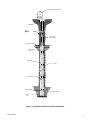
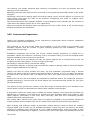
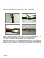
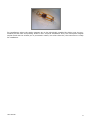
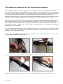
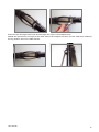
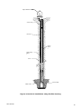
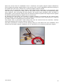
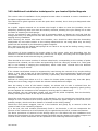
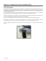
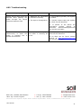
Magnetic Extensometer User Manual Man 007 2.1.1 04/08/2013 Philip Day Chris Rasmussen Chris Rasmussen Manual No. Revision Date Originator Checked Authorised for Issue User Manual 1 Contents Section 1 : Overview ....................................................................................................................................... 3 Section 2 : Installation Techniques ........................................................................................................... 5 2.01 2.02 2.03 2.04 2.05 Section 3 : 3.01 3.02 3.03 3.04 Section 4 : 4.01 4.02 Section 5 : 5.01 5.02 Section 6 : 6.01 6.02 User Manual Borehole preparation .................................................................................................................... 5 Grouting/Backfilling ...................................................................................................................... 5 Instrument Preparation ................................................................................................................ 6 Additional preparation for pre-located Spider Magnets ........................................................ 9 Additional preparation for Flexible Sleeved installations .................................................... 11 Instrument Installation. ....................................................................................................... 13 Safety ............................................................................................................................................. 13 Installation .................................................................................................................................... 13 Additional installation techniques for pre-located Spider Magnets .................................. 15 Additional installation techniques for Flexible Sleeved instruments ................................ 16 Extension of the Magnetic Extensometer through fill ............................................... 17 Access tube extension ................................................................................................................ 17 Installation of Plate Magnets..................................................................................................... 18 Reading procedure .................................................................................................................. 19 Taking Readings .......................................................................................................................... 19 Data Reduction............................................................................................................................. 19 Maintenance and Troubleshooting .................................................................................... 20 Maintenance.................................................................................................................................. 20 Troubleshooting ........................................................................................................................... 21 2 Section 1 : Overview The Magnetic Extensometer System is a geotechnical tool used to measure settlement and heave of soils and rock within foundations and embankments. The instrument consists of permanently polarised ferrous magnets, sealed into two types of settlement targets known as spider and plate magnets. The settlement targets are anchored within the surrounding soil or rock material at levels where movement is to be monitored and are free to slide co-axially along a central, plastic access tube, in the direction of expected movement. A third type of target, a datum magnet, maybe rigidly fixed to the lower end of the access tube beyond the zone of expected ground movement and used as a reference for the settlement targets. Readings are taken using a magnet settlement probe connected to a measuring tape, which is lowered down the plastic access tube and detects the magnetic field of the settlement targets. The level of each settlement target relative to a datum position is noted via the measuring tape, to an accuracy of 1.0 millimetre. A set of datum readings for each target are taken before construction commences and the comparison of subsequent readings taken during and after construction with this datum set, will provide the magnitude and direction of ground movement at each settlement target level during the monitoring period. A diagram of the overall installation arrangement is shown in Figure 1. User Manual 3 Magnet settlement Probe Fill Material Plate Mounted Magne t Telescoping Access Tubing Original Ground Level Spider Sprung Magnet Bore Hole Grout Access Tubing Datum Magnet Stable Ground End Cap Figure 1: Typical borehole and fill installation. User Manual 4 Section 2 : Installation Techniques The installation procedures described in this text are intended as a general guide and flexibility in their interpretation and application will be required, depending on individual site and installation circumstances. 2.01 Borehole preparation The diameter of the borehole should be specified, of between 65 and 225mm depending on settlement target or ‘spider magnet’ model selected. The final depth of the installation and therefore borehole depth should also be specified, along with the precise levels within the borehole of the spider magnets and the fixed datum magnet. Depths of up to 200m are typical. The borehole is normally formed in soils using shell and auger or rotary drilling, with or without casing, depending on soil stability and with a borehole verticality of within 25 of vertical. If casing is required to support the borehole, the exact length of each length of casing and the order of installation must be carefully noted during drilling, as it must be gradually withdrawn from the ground during instrument installation, so that it’s lower end remains above and clear of the installation level of spider magnets, at any one time. When an assembly involves the installation of magnets at close centres or installation in unstable ground conditions, it is important to know precisely the depth of the bottom of the casing so that each spider magnet maybe released immediately the casing clears its installation level and so avoiding the release of a spider magnet within insufficiently cleared casing or the borehole collapsing below over cleared casing, before the spider magnet has been installed at its desired level. 2.02 Grouting/Backfilling Grouting Grout is usually a water based cement-bentonite mix, providing a compressible seal to the borehole. A design of grout mix should be previously determined to match as closely as feasible the compressive strengths of the materials into which the Magnetic Extensometer is to be installed. Given the type of equipment we are installing in a borehole, it is always preferable to pre-grout the borehole by tremmie pipe and to lower the instrument assembly through the liquid grout - not only will it be extremely difficult to negotiate a tremmie tube past pre-installed spider magnets, but also the grout will support the instrument via buoyancy during the installation, reducing the risk of dropping the instrument in the borehole or glued access tube joints parting due to the weight of the installation hanging on a freshly glued joint. Should tube buoyancy become excessive leading to floating of the installation, clean, fresh water maybe poured slowly into the access tube assembly to counteract this. Backfill Alternatively, sand or pea gravel may be used as a post installation backfill through free-draining, granular materials or where re-sealing of the borehole is not essential. This requires that the Magnetic Extensometer equipment be installed into the open borehole before backfilling starts, necessitating that a lowering cord, sufficiently strong be attached to the bottom length of the access tube, which will support the weight of the instrument from below during assembly for installation, until it reaches the base of the borehole. User Manual 5 The lowering cord maybe sacrificed after lowering is completed, as it will not interfere with the operation of the instrument. Backfilling will keep pace with the rate of removal of casing and the sequential release of the spider magnets. Overfilling could lead to settling within the drilling casing, which could be difficult to remove and under filling could leave the walls of the borehole unsupported and liable to collapse, both, scenarios better avoided. Care should be taken with granular backfills, to avoid bridging of the backfill and the creation of voids within the backfill column due to over-rapid filling. Water poured down the borehole after the placement of every 0.5m’s worth of fill, will discourage bridging and benefit the installation. 2.03 Instrument Preparation Careful and complete preparation of the instrument’s components before borehole installation commences is particularly important. The quantities of 3m long access tubes are calculated to suit the depth of the borehole, and amassed, together with the number of spider magnets specified for the installation, a datum magnet and two end caps. Installation equipment will include the chosen release method equipment of release pin or pneumatic cutters and sufficient connecting cord or pneumatic tubing to reach the deepest spider magnet installation from the top of the borehole. PVC glue is used to fix the bottom end cap, the datum magnet and to cement joints of the 3m lengths of access tube together, to form a single rigid length. No bonding is required for EC inclinometer casing. For pushdown magnets, a placing head and sufficient lengths of placing tubes to reach the deepest spider magnet installation are required. Making sure that all gluing surfaces are clean, dry and preferably de-greased using a solvent cleaner, the datum magnet is glued to the bottom length of tubing, 0.5 to 1.0m above the bottom or female end of the access tube. The bottom end cap is then glued onto the female end of the tube. Setting time for the glue will depend on temperature conditions and so the equipment should be handled accordingly, ensuring that the glued fittings are not disturbed and remain dry until they have set sufficiently. The position of the ground level relative to the last length of access tubing once installed to the correct depth, should be calculated and marked with a band of coloured tape. If pneumatic cutters are being used to release the spider magnets, they should be lubricated (by dismantling if necessary) and checked for smooth and free operation before final fitting to their spider magnet, particularly if they have been previously used and their mechanism possibly contaminated with hardened grout. The cutting piston should move freely when air pressure is applied to the pneumatic tubing and excess pressure should exhaust from the air release holes when the piston has fully displaced. After verifying that sufficient length of pneumatic release tubing is fitted to reach the installed magnet depth, plus at least 2m, all available pneumatic cutters may then be fitted to the spider magnets, by wrapping nylon fishing line of 11 kg (25lb) breaking strain, around the spurs in each leaf spring leg and fastening all together, with the nylon line of the upper loop passing through the User Manual 6 two holes at the bottom of the pneumatic cutters’ body and using the slipknot arrangement as shown in photograph 1 below, which will allow all legs to release when the top loop of nylon line is cut. To assist, the leaf spring legs of the spider magnet are supplied with a cable tie positioning the legs in their pre-release position. Once the slipknot arrangement has bean made the cable tie can be cut and removed just prior to installation leaving the legs in position as shown below. Ensure that the three round apertures, in the main body of the spider magnet, indicating the location of the target’s magnets, will be facing upwards when the spider magnet is installed in the ground and that the pneumatic cutter is incorporated into the upper loop of nylon line. Three legged spider magnets will also be installed with their legs pointing upwards. Similarly, if release pins are to be used, all available pins with sufficient pull cord attached, maybe fitted to their spiders, using the rubber bands supplied for binding the spider magnets legs in their restrained positions, either once or twice around depending upon required level of retention, as shown below in photograph 2. Note For dry installations the pins should be greased so that they slide freely through the loops on the rubber bands. User Manual 7 For installations where the spider magnets are to be individually installed by sliding over the preinstalled access tube and pushing down to their required installation level, the first spider magnet maybe fitted with its release pin or pneumatic cutters, but other than this, the instrument is ready for installation. User Manual 8 2.04 Additional preparation for pre-located Spider Magnets For installations where the spider magnets are pre-located on the access tubing with or without the use of the flexible sleeving (Cat.No.2E2.19), the lengths of access tubing need to be labelled according to their order of installation in the borehole and then the positions of the spider magnets on each of these marked access tubes, calculated relative to their borehole installation level. Mark the access tubes with coloured tape at each spider magnet position and then locate a spider magnet, pre-loaded with its release pin or pneumatic cutters and connecting cord or tubing. The length of the release cord or pneumatic tubing connecting each installed spider magnet back to the working platform level will have been calculated, allowing an extra 2 to 3m for working with. Each release cord/tube needs to be marked at its upper end, according to the order of ‘release’ of the spider magnets, starting with ‘1’as the first or lowest spider to be released and working progressively up the borehole. The pre-located spider magnets can be temporarily secured in their position on the access tube using the rubber bands wrapped once around the access tube and then around the spider legs as indicated in the photographs, below. For securing the pneumatic released magnets, tape the body of the magnet to the access tube using a water degradable adhesive tape. Ensure the short loop is in line with the release pin hole in the magnet body. Wrap the long section of the rubber band over the spring legs and back to meet the short end. User Manual 9 Insert the pin through both loops and through the hole in the magnet body. Repeat the process for the legs at the other end of the magnet and then cut the cable ties releasing the leg tension onto the rubber bands. User Manual 10 2.05 Additional preparation for Flexible Sleeved installations The overall flexible sleeve installation arrangement is shown in Figure 2, over. At least a day before installation to allow for setting time, the base weight should be filled with wet concrete to increase its overall weight. A lowering cord of sufficient strength to support the complete instrument weight and of twice the length of the borehole plus at least 4m, will be required to lower the additional weight of this type of installation down the borehole. Un-fully-set glued joints, as during installation, will not support the hanging weight of this equipment. Once the spider magnets have been positioned on the previously determined marks of the labelled access tubes, as for the pre-located spider magnets. The flexible sleeving then needs to be cut into lengths to suit the distance between the fitting at the top of the base weight and the position of the deepest spider magnet and the subsequent inter-magnet distances. Lengths are measured and cut with the flexible sleeving in natural tension. A sharp knife and good wire cutters will be required to cut the flexible tubing. Connections between the spider magnets and the flexible sleeving are made by screwing the threaded rubber cuffs onto either end of the lengths of cut sleeving, slipping one of the supplied hose clips over each cuff, pushing the cuffs onto the magnet body and securing by tightening the hose clips. Connections for lengths of sleeving straddling joints between successive lengths of access tubing are prepared before installation, by securing one end of the sleeving to its spider magnet, the connection at the other end made during installation after making the glued joint of the access tubing which the flexible sleeve straddles. Supporting the spider magnets in position with cord is particularly useful with the flexible sleeving installation, as before release of the spider magnet leaf spring anchors into the surrounding borehole material, the weight of the freely moving assembly of flexible sleeving and magnets tends to drag down the whole assembly, displacing the magnets from their intended installation level, so any support of the magnets prior to their release assists in relieving some of this weight. Individual ‘lifting cords’ should be attached to each spider magnet, which extend back to the surface and are numbered accordingly at the surface, in the same way that the spider release cords are prepared. This will enable the whole magnet and flexible sleeve assembly to be pulled back into position or individual magnet’s vertical positions adjusted when the assembly slumps down. The cords should be tied securely around the main body of each magnet, so that the pulling force acts directly and only on the body and not the flexible sleeving which could be pulled off its fitting to the magnet. As the pulling cords are attached to the magnets, they will not be retrievable and will become part of the borehole backfill. They will have no effect on the performance of the instrument. User Manual 11 Magnet Settlement Probe Access Tubing Bore Hole Flexible Sleevin g Spider Sprung Magne t Grout Sinker Weight Stable Ground Figure 2: Borehole installation using flexible sleeving. User Manual 12 Section 3 : Instrument Installation. 3.01 Safety It should be emphasised here that the restrained leaf spring legs of a spider magnet represent a hazard and a possible cause of injury, should the legs unexpectedly release when in close proximity to personnel. Always keep faces and especially eyes out of the range of released spider magnet legs radius i.e. at least 400 mm away from a restrained spider magnet. This is particularly important when the restraining cable tie has been removed, immediately before installation in the borehole, when it is solely the nylon fishing line restraining the legs which could break if over stressed. 3.02 Installation Once the instrument preparations, borehole drilling and depth verification and any pre-grouting have been completed, we are ready to start installation of the equipment. For push down spider magnets, the required number of access tube lengths are glued together, using PVC cement, as the lengths are inserted into the borehole, starting with the prepared bottom length with its end cap and datum magnet. Ensure the surfaces to be glued are clean, preferably with a solvent de-greaser and dry. Fill the access tube as necessary with clean water during installation to overcome buoyancy. Continue until the required numbers of access tubes are joined and the bottom of the tube reaches the base of the borehole, the correct installation depth confirmed by the previously measured ground level mark on the tube, coinciding with ground level. Any excess stick-up of the access tubing may now be reduced to a convenient level for both drilling team and instrument engineer, by cutting with a hacksaw or similar. An end cap should be fitted whilst not working with the access tubing, to prevent ingress of soil or grout during the casing removal procedure. Start removing casing from below the level of the installation level of the lowest spider magnet and halt when removed to 0.5m above this level. Place the first prepared spider magnet with its attached release mechanism, allocated as the deepest target, over the access tube and remove the temporary leg binding cable tie, so that the spider legs are held bound only by the nylon fishing line. Ensuring that the spider magnet is orientated with its pneumatic cutter or eye of the release pin uppermost, use the placing tubes and attached placing head to push the spider magnet to the required installation level, indicated by the arrival of the mark, taped onto the placing tube, at ground level. Joints between placing tubes are made as tubes are lowered down the borehole, by threaded couplings. Care should be taken whilst descending the spider magnet that its connecting release cord or pneumatic cutter tubing does not snag at ground level, as it is feeds into the borehole. Snagging of the cord or tube could produce excessive pull on the nylon fishing line or release pin and leading to premature release of the spider magnet out of position. The correct level of the spider magnet should be confirmed by reading its position using the settlement probe and adjusted accordingly. User Manual 13 Once the correct level for installation level is confirmed, the spider magnet maybe released by firmly holding the spider magnet down at its correct level via the installation tubes and pulling on the release pin cord until it comes free, confirming spider magnet release. Similarly, for the pneumatic cutter system, after checking the cleanliness of the pneumatic tube end and fitting, screwing the fitting into the pneumatic control unit fitting and tightening lightly with a spanner, then connecting the foot pump to the control unit’s schraeder valve, as shown in photograph 4, the pneumatic tubing down the borehole should be pulled with slight tension against the placing tubing holding the magnet at the correct level. By pumping the foot pump, the increase in system pressure is monitored via the control unit’s pressure gauge, until the piston in the cutter displaces, cutting the nylon restraining line, releasing the spider magnet and liberating the pneumatic cutter. The release cord or pneumatic cutter tubing may now be retrieved from the borehole, carefully coiled and washed clean of grout ready for future use. The above procedures of removal of the drilling casing to 0.5m above the next installation level followed by the spider magnet installation will be repeated for all remaining settlement targets. User Manual 14 3.03 Additional installation techniques for pre-located Spider Magnets The correct order of installation of the prepared access tubes is essential to ensure installation of the spider magnets at there correct level. The tubes will be glued together as with the push down method, but in their pre-designated order of installation. As a spider magnet mounted on an access tube length is about to enter the borehole, the two temporary restraining cable ties must be carefully removed, allowing the nylon fishing line to take the strain of retaining the leaf springs. Cut too, the adhesive tape binding the coil of pneumatic tubing or release pin cord and lead the tubing/cord away in a straight line from the borehole. This will help prevent the cords/tubes from tangling during installation. While lowering the access tube down the borehole, care should be taken that the descending tubes/cords are not under tension or the trailing tubes/cords do not snag whilst they are being pulled into the borehole by the descending spider magnets. Also, make sure that the magnet leaf springs do not catch on the top of the drilling casing, causing the nylon restraining line to break. The process of gluing together the access tubes in the correct order and descending into the borehole is continued until the access tube reaches its full depth, coinciding with the taped ground marker on the last access tube arriving at ground level. There should be the correct number of release tubes/cords, corresponding to the number of spider magnets to be released, at the surface and protruding from the casing by at least 2 m. Take great care in not twisting or tangling the cords/tubes, which could make removal from the borehole difficult after magnet release. If the release cords/tubes cannot be supported by hand during the removal of any surplus drilling casing, it may help to tape all of them together to the top of the extensometer access tube with Denso tape, to prevent accidental loss of a cord (in particular) down the borehole, before its spider magnet is released. Removal of casing from below to 0.5 m. above the lowest spider magnet may now take place, taking care not to snag, tangle or break the release cords/tubes at all stages. Once the casing is clear of the lowest magnet, its release cord or tube is selected from the assembly at the surface and the magnet released as with the push down magnets by gently pulling the cord against the resistance of the temporary securing tape or rubber band. Once released, the now redundant release cord can now be pulled completely from the borehole, thereby reducing the clutter at the top of the borehole. Should the cord snag as it is being pulled up the borehole, only very gentle force should be used to attempt to free it. Excessive force could prematurely release an upper magnet on which the cord is probably caught, which could be a disaster if released in the drilling casing. Should the cord remain snagged, leave it in the borehole and gently try to remove it after the release of each of the remaining magnets. If, in the end, the cord remains permanently fixed in the borehole, it will not compromise the function of the instrument at all and should only be regarded as the loss of a release mechanism. The above procedures of removal of the drilling casing to 0.5m above the next installation level followed by the selection of the relevant release cord/tube and the release of the spider magnet and removal of the release mechanism will be repeated for all remaining settlement targets. User Manual 15 3.04 Additional installation techniques for Flexible Sleeved instruments Due to the additional weight of this instrument, a lowering cord of sufficient strength must be used to support the access tube assembly as it is lowered to the bottom of the borehole. Once the base weight is brought to the side of the borehole, the cord, which should be at least twice as long as the borehole’s depth, is fed through the two eyelets and then preferably tied to a convenient part of the drilling rig. The assembly may now be lowered into the borehole by feeding through the long, unfastened length of the cord, pausing as each access tube is added to make up the length of the instrument. Again, the order of installation of the numbered access tubes is essential for a successful installation. It is advised that the made up access tubes with their fitted spider magnets and flexible slinky sleeving are carefully laid out in order of installation next to the drill rig prior to installation commencing, so that during installation the access tubes fall readily to hand in their correct order. With the flexible sleeving compressed along its length to expose the end of the access tube, the glued joint between the ends of the access tubes can be made. Once the glued joint is secure, the flexible sleeving may be released and pulled back over the joint to the magnet to which it is designed to be attached, where its rubber cuff is pushed on to the fitting of the spider magnet and secured by tightening the hose clip. Continue with this process until the whole instrument is installed and the base weight sitting on the base of the borehole. Once the weight has been relieved from the lowering cord, the cord maybe recovered, by pulling the free end of the cord down the borehole, through the eyes in the base weight and back-up the borehole, by pulling from its fixed end. The process of casing removal and release of spider magnets, as with the pre-located magnet installation process, may now take place with the use of the magnetic reed-switch probe to verify the location of each spider magnet and the inevitable upward adjustment by pulling on the lifting cords. It is advisable to use equal tension on all cords above the spider magnet to be released at the same time, when pulling the assembly back to its correct vertical position, so that the load required for lifting is distributed throughout the assembly and not just on one magnet trying to raise the assembly’s weight. Once pulled back into its correct position, the magnet is released its legs biting into the borehole wall and providing an anchor for the flexible sleeving below to hang from. The effort required to pull the flexible tube assembly in to position will diminish as the release of spider magnets progresses up the borehole and the amount of unsupported assembly diminishes. User Manual 16 Section 4 : Extension of the Magnetic Extensometer through fill 4.01 Access tube extension The vertical extension of extensometer access tubing through and placement of settlement targets within fill material, as during the construction of an embankment for example, involves the use of a telescoping access tube system, catalogue items 2E 2.2 and 2.3, to accommodate the high degree of settlement experienced within fill, without buckling the access tube and the Plate Magnet, item 2E1.9, as settlement targets. Figure 3 shows the arrangement of the alternating smaller and larger diameter, 2 m. long, telescoping access tubes and their internal initial overlap and placement of the sealing ‘O’ rings. 500 mm Access Tube 33.4mm O.D. 'O' Ring 500 mm 1000 mm Access Tube 48.5mm O.D. Access Tube 33.4mm O.D. Figure 3: Extensometer Access Tube Compression Joint User Manual 17 Assembly of the access tubes involves the cleaning and drying of the smaller diameter, male tube and the slipping over the end of the tube, of 2 ‘O’ rings, one of which should be pushed down the tube by 350mm. and the 2nd by 50mm. from the tube’s end. The larger diameter, female tube is then pushed over the male tube and its O-rings, so that there is an overlap of the inner and outer tubes of 500mm. As the tubes slide along each other, the motion should feel smooth and offer a decent resistance, indicating a good fit and sealing of the joint. If the motion is jerky or resistance small, then slide the joint apart, clean all mating surfaces and O-rings and re-fit. Once satisfactorily made, it is prudent to wrap some Denso type grease tape around the entry to the joint, preventing the ingress of fill material into the joint and interference with its smooth telescopic movement. Placement of fill material immediately around the extended access tube must be carefully placed by hand, ensuring the extended tube is kept vertical and not buried at an angle. The fill is then compacted using a pedestrian vibrating compactor or similar taking care to avoid direct contact with the tubes. The rate of tube extension will keep pace with the rate of filling, ensuring at least 0.5m. of protrusion of the access tube above the fill level at all times. The end caps 2E2.9 & 2.10 accordingly, should be fitted to the top of the access tube at all times to prevent ingress of fill or other material inside the tube, which could block and lead to the possible loss of the instrument. The access tube should also be fenced off using sturdy and highly visible barriers, to help avoid damage by site plant movements. 4.02 Installation of Plate Magnets Plate magnets are quite simply installed by slipping the plate over the top of the smaller diameter access tubing and lowering down to the compacted and prepared horizontal fill surface at the required installation elevation. It is then buried in selected, loose, stone-free fill material to a depth of at least 300mm, which is then carefully compacted as before, ensuring the verticality of the access tube. User Manual 18 Section 5 : Reading procedure 5.01 Taking Readings The magnet settlement probe comprises a stainless steel sensor probe fitted to a graduated cable, wound on a reel containing a battery powered audio and visual indicator. The probe incorporates a precision reed switch which is closed by the presence of a magnetic field. Once the probe detects the position of the target magnet in the borehole, the audio indicator will sound and the visual indicator will be illuminated. The depth of the probe is then recorded by reading the tape graduation at the top of the borehole. Care should be taken to ensure that the tape is read at the same reference mark at the top of the borehole each time a depth reading is taken to ensure maximum accuracy of readings. The probe should be lowered down the borehole until the first magnet is detected, raise the probe until the indicators stop and then re lower carefully until the point where the indicators are activated. Record the tape measurement at the reference point (usually the top of the casing) at the top of the bore hole. For greater accuracy take several readings and average the readings. Repeat the procedure for all magnets down the bore hole including the datum magnet. This establishes a base set of magnet positions the same reading procedure should be established for subsequent reading sets 5.02 Data Reduction If the datum magnet has been installed in solid ground i.e. that in which no settlement will take place, then the settlement of the magnet positions is calculated as follows: (D0 – M0) - (D1 – M1) Where: D0 is the initial reading from the reference point to the datum magnet M0 is the initial reading from the reference point to the magnet D1 is the subsequent reading from the reference point to the datum magnet M1 is the subsequent reading from the reference point to the magnet E.g. The initial reading on the datum magnet read 27.252m at the reference point (D0) The initial reading on magnet number 6 read 15.620m at the reference point (M0) The subsequent reading on the datum magnet reads 26.728m at the reference point (D1) The subsequent reading on the magnet number 6 reads 15.115m at the reference point (M1) (D0 – M0) - (D1 – M1) = (27.252 – 15.620) – (26.728 – 15.115) = (11.632) – (11.613) = 0.019m The settlement of magnet number 6 is 0.019m relative to the datum magnet. Where the datum magnet is not in solid ground or the magnet position relative to the reference point at the top of the borehole are required, then the magnet positions are recorded along with an elevation survey of the reference point for each reading set. The magnet position readings are then subtracted from the surveyed elevation of the reference point. Settlement of each magnet position is calculated by subtracting the subsequent magnet position from the initial magnet position. User Manual 19 Section 6 : Maintenance and Troubleshooting 6.01 Maintenance The magnet settlement probe and reel assembly is a simple system and should give long and reliable service. After the probe has been used the cable should be carefully cleaned and rewound onto the reel. The magnet settlement probe has no on/off switch; the circuit is only activated when a magnetic field is present. It is not necessary to turn the probe off between boreholes or even between days, but it should be switched off (by removing the battery) if not in use for a prolonged period of time. To Remove the battery or to replace an exhausted battery unscrew the three fixing screws from the reel front faceplate and carefully lift away to expose the battery. Take care not to damage any of the wiring. Ensure you have a new ‘PP9’ 9V battery to hand. The battery is secured by a Velcro strip attached to the battery (see photo below). Carefully withdraw the battery, remove the Velcro strip, attach it to the new battery and re-install. Carefully replace the faceplate ensuring that wires are not trapped and re-tighten the three fixing screws. User Manual 20 6.02 Troubleshooting Condition / Symptom Possible Causes Recommended Action Buzzer and/or lamp does not activate when passing the probe through the target magnets magnetic field 1: Batteries are exhausted, or inserted incorrectly 1: Check battery polarity and replace if needed 2: The tape is damaged/cut 2: Visually inspect tape and replace if a fault can be identified 3: If neither of the above are successful contact Itmsoil at www.Soil Instrumentssupport.com for service and repair Buzzer and lamp activate continuously or when the probe is inserted into a known wet borehole The tape is damaged/cut and water is shorting the circuit Visually inspect tape and replace if a fault can be identified If no fault can be found contact itmsoil at www.itmsoilsupport.com for service and repair Bell Lane, Uckfield, East Sussex t: +44 (0) 1825 765044 e: [email protected] TN22 1QL United Kingdom f: +44 (0) 1825 744398 w: www.itmsoil.com Soil Instruments Ltd. Registered in England. Number: 07960087. Registered Office: 5th Floor, 24 Old Bond Street, London, W1S 4AW User Manual 21