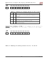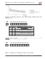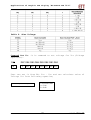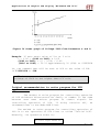
1
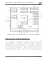
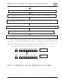
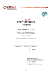
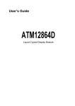
Applications of Graphic LCD Display “ET-NOKIA LCD 5110”
User’s Manual of
Graphic LCD “ET-NOKIA LCD 5110”
Specifications of LCD 5110
48 x 84 Dot LCD Display
Serial Bus Interface with maximum high speed 4.0 Mbits/S
Internal Controller No.PCD8544
LED Back-Light
Run at Voltage 2.7 -5.0 Volt
Low power consumption; it is suitable for battery
applications
Temperature range from -25˚C to +70˚C
Support Signal CMOS Input
LCD 5110 is 48 x 84 Dot LCD Graphic that has internal
Controller/Driver “PCD8544” to control all displays and
operations. Diagrammatic structure of internal Controller
PCD8544 is shown as in figure 1.
- 1-
www.ett.co.th
Applications of Graphic LCD Display “ET-NOKIA LCD 5110”
Figure 1 shows internal structure of Controller PCD8544.
Handling of LCD Address (Addressing)
The address arrangement of memory that is shown on LCD
Display (DDRAM) is Matrix that consists of 6 rows (Y Address)
from Y-Address 0 to Y-Address 5 and 84 columns (X Address)
from X-Address 0 to X-Address 83. If user wants to access to
the position of displaying result on LCD Display, must refer
to the relationship between X-Address and Y-Address. Data that
will be sent to display is 8 bit (1 Byte) and it will be
arranged as vertical line; in this case, Bit MSB will be lower
and Bit LSB will be upper as shown in the following picture;
- 2-
www.ett.co.th
Applications of Graphic LCD Display “ET-NOKIA LCD 5110”
Figure 2 shows structure of Address and Data of LCD Display.
- 3-
www.ett.co.th
Applications of Graphic LCD Display “ET-NOKIA LCD 5110”
We can write data into the address of memory (DDRAM)
continuously and values of X-Address and Y-Address will be
increased automatically. In this case, there are 2 methods to
configure the operation format of address; firstly, Vertical
Addressing Mode (V=1), 1 value of Y-Address will be increased
every time (see figure 3); and secondly, Horizontal Addressing
Mode (V=0), 1 value of X-Address will be increased every time
(see figure 4).
Figure 3 shows the increase of address value on the vertical
line (Vertical Addressing Mode (V=1)).
Figure 4 shows the increase of address value on the horizontal
line (Horizontal Addressing Mode (V=0)).
- 4-
www.ett.co.th
Applications of Graphic LCD Display “ET-NOKIA LCD 5110”
Connection for controlling LCD Display
The signal connection for controlling operation of LCD is
Serial format and there are several pins as follows;
1
2
3
4
5
67
8
1
2
3
4
5
6
7
8
LED(+)
SCLK
SDIN
D/C
RESET
SCE
GND
VCC (2.7-5V)
Figure 5 shows the pin positions of LCD.
Table 1: Function of Pin LCD
Pin’s Name
1. VCC
Functions
Pin +VCC; using Power Supply from 2.7 – 5 VCD
- 5-
www.ett.co.th
Applications of Graphic LCD Display “ET-NOKIA LCD 5110”
2. GND
3. SCE
6. SDIN
7. SCLK
Pin Ground
Pin CHIP ENABLE to control operation of Pin
Controllers
Signal RESET for operation of LCD
Pin to configure the data formats between Data
and Command.
Pin DATA (SERIAL DATA LINE)
Pin CLOCK (SERIAL CLOCK LINE)
8. LED
Pin to control operation of LED (Back Light)
4. RESET
5. D/C
Communication Format
The format of command that is used to communicate with
LCD is divided into 2 modes; Command Mode and Data Mode. In
this case, it uses Pin D/C to divide and control signals; if
D/C = 0, the data that is sent to LCD is Command (see more
detailed information of commands in the Table 1); and if D/C =
1, the data that is sent to LCD wil1 be Data and it will
placed in DDRAM Memory (Display Data RAM) to be displayed on
LCD Display. After 1 byte data has already been written, 1
value of DDRAM address will be increased automatically. The
format of data will be serial and it will send MSB (The Most
Significant Bit) first. Generally, its structure is displayed
as follows;
Figure 6 shows the general format of Data.
There are 2 methods to send data into LCD; firstly,
sending 1 Byte data in each time and secondly, sending many
continuous bytes. The Data format is shown as follows;
Sending 1 byte data in each time
- 6-
www.ett.co.th
Applications of Graphic LCD Display “ET-NOKIA LCD 5110”
Figure 7 shows the format of sending 1 byte data in each time.
Sending continuous data (more than 1 byte)
Figure 8 shows the format of sending the continuous bytes
data.
If Pin SCE is in the status of High, any change at signal
SCLK is not be affected on LCD; user can send data to LCD when
Pin SCE is in status of LOW only. Data will be shifted to Pin
SDIN follows the interval of signal CLOCK (Rising Edge). In
this case, LCD determines the data to be either Command Mode
or Data Mode from status of Pin D/C; if D/C = 0, it is Command
Mode; but if D/C = 1, it is Data Mode.
Pin SCE is still Status LOW (SCE = 0) until data byte
will be sent successfully as shown in the figure 9.
- 7-
www.ett.co.th
Applications of Graphic LCD Display “ET-NOKIA LCD 5110”
Figure 9 shows diagram of signal RES that is in status of
High.
The method to create Signal RESET (RES) is to create
Pulse Low at Pin RES; if Signal RESET is occurred (RES = 0)
while sending 8 bit data (1 byte) is not complete, data in
that byte will be canceled. When status of signal RES is in
High (RES = 1), at the next Signal Clock+ will be data that
starts at Bit 7 of data again as shown in the figure 10.
Figure 10 shows diagram of signal RES that is in the status of
RESET.
- 8-
www.ett.co.th
Applications of Graphic LCD Display “ET-NOKIA LCD 5110”
Figure 11 shows the period of occurring Signal RESET.
Figure 12 shows the period of signals.
Table 2: Parameter values
- 9-
www.ett.co.th
Applications of Graphic LCD Display “ET-NOKIA LCD 5110”
Table 3: Commands Sets for controlling LCD Display
- 10-
www.ett.co.th
Applications of Graphic LCD Display “ET-NOKIA LCD 5110”
Table 4: Detail of Parameter values from Table 3
Detail of Commands
- 11-
www.ett.co.th
Applications of Graphic LCD Display “ET-NOKIA LCD 5110”
Command NOP: No Operation
D/C
0
DB7 DB6 DB5 DB4 DB3 DB2 DB1 DB0
0
0
0
0
0
0
Command Function Set:
operations of LCD.
It
is
D/C
0
0
0
command
to
set
function
for
DB7 DB6 DB5 DB4 DB3 DB2 DB1 DB0
0
0
1
0
0
PD
V
H
-PD: It is Bit to select operation mode.
PD=0: Active Mode
PD=1: Power-Down Mode
-V: It is Bit to select the format of increasing address value
of (DDRAM) Memory.
V=0: It increases address value on the horizontal line
(Horizontal Addressing Mode) see figure 4 above.
V=1: It increases address value on the vertical line
(Vertical Addressing Mode) see figure 3 above.
-H: It is Bit to select format of using commands of SCD.
H=0: Using the basic commands (see more information from
Table 3)
H=1: Using the additional commands (see more information
from table 3)
Command Write Data: It is command to write data into DDRAM
Memory to display result on LCD Display.
D/C
1
DB7 DB6 DB5 DB4 DB3 DB2 DB1 DB0
D7
D6
D5
D4
D3
D2
D1
D0
D7-D0: It is 8 Bit data that must be written to display on
LCD Display.
Command Set in Basic Mode (H = 0)
Command Display Control: It is command to control displaying
result on LCD Display.
- 12-
www.ett.co.th
Applications of Graphic LCD Display “ET-NOKIA LCD 5110”
D/C
0
DB7 DB6 DB5 DB4 DB3 DB2 DB1 DB0
0
0
0
0
1
D
0
E
Table 5: Meaning of setting values in Bit D and E
D
E
Meaning
0
0
0
1
1
0
1
1
Data on the LCD Display is in status
of blank or not display (Display
Blank).
It displays results as usual (Normal
Mode).
Data at every positions on the
display is in status of ON.
Display data on LCD Display inversely
(inverse Mode)
Command Set Y-Address of RAM: It is command to set value of YAddress in RAM Memory; in this case, Y value is in the range
of 0 to 5.
D/C
0
DB7 DB6 DB5 DB4 DB3 DB2 DB1 DB0
0
1
0
0
0
Y2
Y1
Y0
Table 6: Meaning of setting values into Y2, Y1 and Y0
- 13-
www.ett.co.th
Applications of Graphic LCD Display “ET-NOKIA LCD 5110”
Y2 Y1 Y0
0 0 0
0 0 1
0 1 0
0 1 1
1 0 0
1 0 1
Position of Y-Address
Bank 0
Bank 1
Bank 2
Bank 3
Bank 4
Bank 5
Command Set X-Address of RAM: It is command to set value of XAddress of RAM Memory.
D/C
0
DB7 DB6 DB5 DB4 DB3 DB2 DB1 DB0
1
X6
X5
X4
X3
X2
X1
X0
Value of X-Address on LCD Display is in the range of 0 to
83; so, the method to set position address of X-Address of X6,
X5, X4, X3, X2, X1 and X0 must be in the range of 0000000
(00H) to 1010011 (53H).
Command Set in addition mode (H = 1)
Command Temperature Control: It is command to control
temperature
to
be
in
the
suitable
range.
From
the
specification of LCD that is fluid; if it is in too low
temperature, it maybe sticky and display results incompletely.
So, it is necessary to compensate the temperature value to be
in the suitable range; in this case, user must select value of
coefficient VLCD suitably. There are 4 values and can set them
by Bit TC1 and TC0.
- 14-
www.ett.co.th
Applications of Graphic LCD Display “ET-NOKIA LCD 5110”
Figure 13 displays graph of the relationship between VLCD and
temperature.
D/C
DB7 DB6 DB5 DB4 DB3 DB2 DB1 DB0
0
0
0
1
0
0
0
TC1 TC0
Table 7: Meaning of setting Bit TC1 and TC0
TC1 TC0
0
0
1
1
Coefficient value of VLCD and
Temperature
VLCD temperature coefficient 0
VLCD temperature coefficient 1
VLCD temperature coefficient 2
VLCD temperature coefficient 3
0
1
0
1
Command Bias System: It is command to
Voltage Level by Bit BS2, BS1 and BS0.
D/C
0
set
value
of
Bias
DB7 DB6 DB5 DB4 DB3 DB2 DB1 DB0
0
0
0
1
0
BS2 BS1 BS0
Table 8: Meaning of setting Bit BS2, BS1 and BS0
- 15-
www.ett.co.th
Applications of Graphic LCD Display “ET-NOKIA LCD 5110”
Table 9: Bias Voltage
Command Set VOP: it is command to set voltage for VLCD (Voltage
Operation).
D/C
0
DB7 DB6 DB5 DB4 DB3 DB2 DB1 DB0
1
VOP6 VOP5 VOP4 VOP3 VOP2 VOP1 VOP0
User can set it from Bit VOP6 – VOP0 and can calculate value of
Voltage VLCD from following equation;
VLCD = a + (VOP6 to VOP0) x b
Coefficient value
a = 3.06
b = 0.06
- 16-
www.ett.co.th
Applications of Graphic LCD Display “ET-NOKIA LCD 5110”
Figure 14 shows graph of Voltage VLCD from Parameter a and b.
Example: If user wants value of VLCD at 5 volt
5 = 3.06 + (VOP6 to VOP0) x 0.06
(VOP6 to VOP0) = (5 - 3.06) / 0.06
(VOP6 to VOP0) = 32.33 approximately 32 (20H) or 0100000B
So, the command that will be sent to LCD to set value of VOP
is 11000000B or C0H.
NOTE: Do not set value of VOP too high, the maximum
voltage of VLCD is not higher than 8.5 volt.
Initial recommendation to write program for LCD
applications
The method to write program for controlling operation
of LCD whichever Microcontroller family or number is the same
because user must writes program to create signals for
controlling operation of LCD. If using function SPI, we
recommend user to use Mode MSB First.
The method to write program for controlling operation of
LCD is to set operation of LCD first or called “Initial LCD”.
Normally, its operation order is;
To create signal RESET LCD
- 17-
www.ett.co.th
Applications of Graphic LCD Display “ET-NOKIA LCD 5110”
To send Command 21H for selecting the Command Set in addition mode (H = 1)
To send Command Set Voltage VOP; for example, sending Command C0H (VOP = 5V)
To send Command for setting value of Temp Control; for example, sending
Command 07H (VLCD temperature coefficient 3)
To send Command to set value of Voltage Bias System; for example, 13H (n=4, 1:48)
To send Command 20H for selecting the Command Set in basic mode (H = 0)
To send Command 0CH (D=1, E=0) for setting LCD to display results in Normal Mode
After the procedure of Initial LCD is completely, user
can write program and send data to display at positions of
LCD. Generally, user must specify the required positions of XAddress and Y-Address to display results first.
For example, setting position X = 0, Y = 0 as follows;
D/ C
0
D/C
0
DB7 DB6 DB5 DB4 DB3 DB2 DB1 DB0
1
0
0
0
0
0
0
0
DB7 DB6 DB5 DB4 DB3 DB2 DB1 DB0
0
1
0
0
0
0
0
0
X-
Y-
Table 10: Example of creating characters on LCD Display
- 18-
www.ett.co.th
Applications of Graphic LCD Display “ET-NOKIA LCD 5110”
Table 10 (Continue): Example of creating characters on LCD
Display
- 19-
www.ett.co.th
Applications of Graphic LCD Display “ET-NOKIA LCD 5110”
- 20-
www.ett.co.th