1
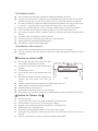
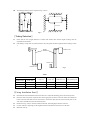
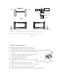
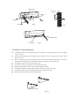
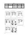
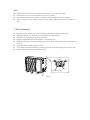
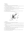
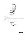
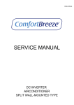
SPLIT TYPE WALL MOUNTED AIR CONDITIONER
INSTALLATION
MANUAL
Read the manual carefully before operation and keep it for reference.
〖Installation Guide〗
z
z
This air conditioner meets the safety and operation standards promulgated by the Nation.
You need to invite professional air conditioner service and maintenance personnel to install or remove the air
conditioner. Problems may occur and you may suffer losses if non- professionals install the air conditioner.
z
User shall provide the power that meets installation and operation requirements. The voltage for this product
is: 198~253V~, voltage beyond this scope will affect the normal operation of the air conditioner.
z
Separate power point with delay fuse protector or automatic breaker should be used for the air conditioner.
z
The air conditioner must be correctly and reliably grounded, or it may cause electric shock or fire.
z
Do not switch on the power of the air conditioner before well connecting and carefully checking the tubing
and wires.
z
The appliance shall not be installed in laundry or bathroom.
z
In case necessary, please consult your supply authority for system information.
z
The plug shall be accessible after installed the appliance.
z
This instruction is subject to change without notice.
〖Installation of Accessories〗
z
Examine carefully the attached packing list and check whether the accessories are complete.
z
Users may need to buy at their own expenses the articles not included in the packing list and may be needed
in installing.
〖Position for Indoor Unit〗
z
Away from the place where there is heat source, steam
source, leakage of flammable gas and smoke.
z
At least 15cm
No obstacles near the inlet and outlet, and keep good
ventilation.
z
At least 1m away from wireless equipment (such as TV,
z
Mounted on the wall that can bear the weight of the air
radio etc.).
Indoor unit
conditioner and won't produce noise while unit
At least 15cm
Good discharge for water.
At least 15cm
z
Fig.1
working.
z
The distance between the indoor unit and the floor should be greater than 2.3m.
z
The plug shall be accessible after installing the appliance.
z
z
z
Ensure the distance as required in Fig.1.
The back of the indoor unit should be close to the wall(Fig.1)
The all figures are only schematic, and they may be slightly different from the actual appliances you selected.
〖Position for Outdoor Unit〗
z
Avoid direct sunlight.
z
Away from heat source, steam source, leakage of flammable gas, smoke and dust.
z
Select a place that is away from rain (snow) and has good ventilation.
z
Neighbors will not be affected by the blown wind and noise, or discharged water.
z
The place that is easy to install and service.
z
Mounted on the solid and reliable foundation will not increase noise or shock.
z
To get high cooling performance, make sure the unit's front, rear, left and right sides must be located in an
z
The outlet is proposed to be in open air, any obstacle will affect the performances.
open area.
z
The installing distance must be required as Fig. 2 shows.
At least 2m
At least 10cm
At least
15cm
40cm
Blackage
Air outlet
Outdoor unit
Air inlet
At least
At least 2m
Fig.2
〖Tubing Selection〗
z
Ensure that the level (height) difference of indoor and outdoor units and the length of tubing meet the
requirement In the Table 1.
z
If the tubing is longer than 7m, but shorter than 15m, refrigerant should be supplemented according to Table
1.
Indoor unit
Height
difference
Outdoor unit
Indoor unit
Outdoor unit
Fig.3
Table 1
Tubing Size
Narrow (mm)
Wide (mm)
Standard tubing
Length (m)
Max tubing
Length (m)
Height
Difference (m)
Additional
refrigerants(g/.m)
φ6.35(1/4”)
φ9.52(3/8”)
3.5
9
5
15
φ6.35(1/4”)
φ12.7(1/2”)
3.5
12
7
15
φ6.35(1/4”)
φ15.88(5/8”)
4
15
8
15
〖Fixing Installation Panel〗
z
Dismantle the metal installation board of the indoor unit. Adjust the mounting panel to horizontal position.
z
Drill holes and insert plastic expansion tubes at the appropriate locations on the wall and fix the installation
board on the wall with M5x30 screws and washer 6. Ensure that there must be at least 4 fixed points in the
wall. Ensure installation board to horizontal position.
z
Drill holes as Fig. 4 shows. The hole, 80mm in diameter, should slightly slide down outwards..
z
Cut PVC tubes at a slight angle in the length shorter than wall thickness and inset it into the hole.
z
Mount the wall cap.
Wall
Indoor
Right side
Left side
Outdoor
PVC tube
Wall cap
Small angle
Fig.5
Left
Right
Right
Left
horizontal direction
horizontal direction
left chart is available for the position of drain hose. refer to fig.7
Right chart is available for the position of drain hose. refer to fig.9
Fig.4
〖Indoor Unit Installation〗
The tube may be connected in several directions as shown in Fig.7.
1. Connecting right back tube (similar to right lower tube)(optional)
z
Pull out the tubing from bottom of the chassis; and connect the drainpipe. Strap the joint of tubing reliably.
z
Lead the connecting wire to the indoor unit (Do not connect to the
Pipeline
power).
z
Strap together the tubes, discharge pipe and connecting wire with
adhesive tape. The discharge pipe is put at the below.
z
Remove the board which is on the chassis.
z
Check if the connections are reliable.
z
Mount the indoor unit on the two hooks at the upper part of installation
board.
z
Drain pipe
Units connecting wires
2. Connecting left back tube (similar to left lower tube). Fig. 9
Move the discharge tube to the left side, and discharge cap to the right
side.
z
Fix the tubes in the slot of the indoor unit with the fix clamp.
z
The following mounting steps are the same as those in “1. Connecting right back tube.”
Fig.6
Drain hose
Installation
board
Wall
Leftward
Rightward
Fixed clamp
Leftback
Rightback
Downward
Fig.7
Fig.8
Drain hose
Fixed clamp
Fig.9
〖Outdoor Unit Installation〗
z
If installation brackets for installing outdoor unit are needed, user could buy the brackets from our company
or agents(Fig.10).
z
Assemble the mounting frame and supports with the attached 6 screws ( M12x25), plain washers, spring
washers, and nuts.
z
Drill 4 or more holes on the wall according to the feet size of the air conditioner. Determine the locations for
mounting left and right supports. Ensure that the left and right supports are on the same level.
z
Fix installation frame on the wall with expansive bolts.
z
Fix outdoor unit with 4 bolts (M10x25) on the installation brackets.
z
Fittings must be tightly screwed; Connection must be tight and reliable.
z
In installing outdoor unit, the body should be hung with ropes to prevent from falling.
z
In installing or repair, tools and components should be prevented from falling.
z
Regularly check the reliability of the installation frame.
Installation support
Fig.10
〖Tubing Connection〗
z
Detach the valve cover of outdoor unit.
z
Align flaring nut to the thread center, and screw the nut tightly by hand.
z
Screw tightly the flaring nut with torque spanner until the torque spanner produces "click” sound.
z
It is recommended to use torque spanner to connect the tubing. If other flexible or fixed spanner is used, it
may damage the horn mouth due to improper force.
z
The bending angle of the tube should not be too small or the tube may break up, so the service personnel
should use tube bender to bend the tube.
z
Never let water, dust or sand gets into the pipe.
Table 2
Thread
Flaring nut
Pipeline
Wrench
Torque Wrench
Fig.11
Tubing size (mm)
Torque
(N. m)
ф6.35 (1/4”)
15~20
ф9.52(3/8”)
35~40
ф12.7(1/2”)
50~55
ф15.88(5/8”)
68~82
〖Connection of Wires〗
electric cover
1. Indoor unit
z
Open upward the inlet grid to the greatest extends.
z
Remove the electric cover from the unit.
z
Loose the screw at connection lid. (Fig.12)
z
Dismantle the wire pressure plate.
z
Connect the power connecting wires and signal control
wire separately to the corresponding terminals. (In Fig.14,
please choose the same wiring diagram just with the wiring diagram of unit .)
z
Loose off the screw on the earth plate; press earth wire tightly.
z
Press tightly the connecting wires of the unit with lead wire pressure plate.
z
Close the connection lid screw it tightly and close the inlet grid.
Fig.12
2. Outdoor unit
z
Unscrew and dismantle the electronic device lid(Fig.13).
z
Dismantle the pressure plate of wire fastener.
z
Connect the connecting wires of the unit separately to the corresponding
z
Press tightly the connecting wires of the unit with top pressure plate.
z
Remount the electronic device lid to the original position.
terminals. (Fig.14)
If user wants to prolong or replace the power wire, please do it according to
Fig.13
the table(Table3).
screw
Table 3
Power connecting wires
Signal control wire
10m
Max. Length
5m
10m
≥2.5 mm
≥1.5 mm
≥1.5mm2
≥2.5 mm2
≥1.5 mm2
≥2.5 mm2
2
7K/9K/12K/16K
Power cord
2
Cross sectional area
18K/21K/24K
7K/9K/12K/16K
Brown
1
Brown
1
2
3
4
5
Blue
N
Yellow/Green
Gray(White)
Black
Brown
1
2
N 2
3
3
4
4
4
5
5
5
1
1
N 2
2
3
3
4
5
Blue
N
Yellow/Green
18K
Gray
N
Yellow/Green
Blue
Brown
21K/24K
1 L
2 N
3
4 L1
Fig.14
Brown
Blue
Yellow/Green
Black
2
3
4
Brown
Blue
L 1
N 2
3
L1 4
3
4
7K/9K
Yellow/Green
Blue
N 2
Black
Brown
1
Yellow/Green
1
Yellow/Green
Brown
5
Blue
N
Yellow/Green
1
N 2
Notes:
z
Earthing screw must use special screw(stainless machining screws or copper screws M4)
z
Ensure that all wires are securely connected, will not loose or separate.
z
Ensure that wire connections are carried out according to the wiring diagram of the air conditioner.
z
The above figures are only schematic, and they may be slightly different from the actual appliances you
select.
〖Tube Strapping〗
z
Strapping with PVC Protective tape must be careful, do not damage the pipeline and drain pipe.
z
Strapping should start from the lower part of the outdoor unit to the indoor unit.
z
Fix the PVC tape with adhesive tape to prevent loosing.
z
Drainpipe should slightly slide down outwards to ensure drainage well.
z
When the indoor unit is lower than the outdoor unit, bend the tube to proper extent to prevent water draining
into house.
z
Fix the tube bundle with tube clamps on the wall.
z
Allow enough space between discharge pipe and the ground. Do not put the discharge pipe in water or ditch.
z
Seal the external wall holes with sealing gum or putty.
Wall
Clamp
PVC protective tape
Fig.15
〖Exhaust〗
1.
Exhausting type
z
Make sure that all the tubes of indoor and outdoor unit are connecting well.
z
Take off valve bonnet and service port valve bonnet from two-port valve (small pipe cut-off valve) and
three-port valve (large pipe cut-off valve).
z
Turn counter-clockwise 1/4 turn the spool of two-pot valve, close after 10 seconds.
z
To check whether there are leakage at all connections.
z
If there is no leakage, turn again two-port valve counter-clockwise 1/4 turn, at the same time hold out against
the exhaust from valve inside of service port of three-port valve for 10 seconds.
z
Open two-port and three-port valves for running.
z
Screw tightly the valve bonnet.
z
Check with soap water or leak detector whether there are leakage at all indoor and outdoors’ connections.
z
Put the valve bonnet and valve cover back to the position.
Narrow tube
Wide tube
Open
Service valve
2.
Fig.16
Pumping type
z
Make sure that all the tubes of indoor and outdoor unit are connecting well.
z
Take off valve bonnet from two-way and three-way valves by spanner; connect vacuum pump and compound
valve to the service valve bonnet.
z
Open the low-pressure switch of compound valve, and run vacuum pump until units’ internal pressure at 10
mmHg.
z
After pump vacuum, close the low-pressure switch of compound valve, and then close vacuum pump. Turn
。
anti-clockwise 90 Spool of narrow pipe service valve by hexagon spanner, tightly with clockwise turning
after stopping for 10 seconds.
z
Check with soap water or leak detector whether there is leakage at all connections of indoor and outdoor unit.
z
Open wide and narrow pipe service valves by hexagon spanner for running.
z
Take off the connection pipeline of wide pipe service valve.
z
Screw tightly the entire valve bonnet by torque spanner.
z
Check with soap water or leak detector whether there are leakage at all indoor and outdoors’ connections.
z
Put the valve bonnet and lid back to position.
Fig.17
〖Drainage〗
1.
No need drainage treatment
In regions where become cold in the winter, don't install the drain elbow joint to prevent drain water from
freezing and causing the fan to be damaged. This drainage treatment is not necessary for cooling-only type air
conditioner.
2.
z
When need drainage treatment
Please use drain elbow joint (in accessory bag). Outdoor unit should be placed on blocks.
Chassis (outdoor)
Elbow joint
Drain pipe
(buy it by user)
Fig.18
JUZ3.867.248AS19