1
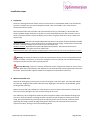
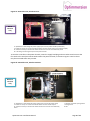
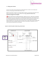
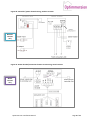
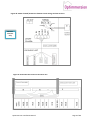
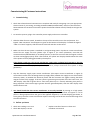
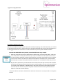
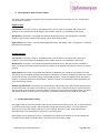
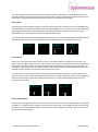
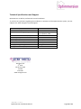
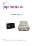
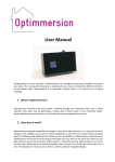
Installation Manual The system should only be installed by a suitably qualified person. It is recommended you read these instructions before you begin the installation, but in summary: 1. Inspection Assess the existing electrical wiring to ensure that it is suitable for the installation of Optimmersion. 2. Mount controller unit Mount the power throttle in a suitable location and the controller in its chosen location. 3. Wiring controller to power throttle This is for the wired versions only 4. Wiring power throttle Install the associated cables and make connections as per Figures 1 to 5. Commissioning & Customer instructions Electrically test the circuitry and then energize the system and carry out the commissioning steps as described, remembering to show the householder how it works. General information Optimmersion measures how much power is flowing through the electricity meter using a current transformer which clips around the live wire of the feed from the Grid. When there are more than 50 watts being exported, it brings up the immersion heater (water heater), always adjusting the exact level so as to maintain the exported power below about 200 Watts. Electric appliances can be turned on and off in the house and Optimmersion makes the appropriate adjustment. Optimmersion (excluding the Simple version) also measures the amount of power being generated by the PV installation using a second clip-on current transformer, this information is displayed, but has no effect on the control of the waterheater. What’s in the box? Optimmersion version 1 x Controller unit 1 x Power throttle 1 x Wireless power throttle CT clips with phono plug terminations 1 x Control signal cable with phono plug 1 x Power supply cable with power plug 1.5m of 5-core cable PVC cable glands 4x Mounting screws for controller 1 x AC power supply 1 x Wattson display 1 x Wattson display power supply Simple Wired Wireless Optismart Hot Water 1 2 2 2 You will also need screws and the appropriate wall fixings for the power throttle. Optimmersion Installation Manual Page 2 of 12 Installation steps 1. Inspection Assess the existing immersion heater circuit to ensure that it is a dedicated radial circuit fed directly from the consumer unit. Any other equipment which is also connected to this circuit must be disconnected and re-wired. We recommend that the controller and associated AC circuitry is protected by a 30 mA RCD. Our chosen modular design allows the controller unit to be mounted away from the consumer unit in a more convenient position so that the display can be seen at a glance with ease, sensor cables are 2 metres long. Wired versions: Optimmersion Simple & Optimmersion Wired. The power throttle should be installed adjacent to the property’s main consumer unit, incoming electrical supply, and the point at which the PV plant’s dedicated supply circuit connects to the consumer unit. Wireless versions :Optimmersion wireless & Optismart Hot Water. The power throttle can be installed anywhere along the immersion heater spur. Please note that there are separate wiring diagrams and instructions for wired and wireless versions. Warning: the power throttle may run hot at times! Mount the unit on a non-flammable vertical surface and make sure that air is free to run through the vents. If in doubt, we recommend spacing the power throttle from the wall surface by 10 mm. UK only Warning: inspect the existing immersion heater integral thermostat to ensure that it complies with safety requirements and regulations to provide thermal overload protection where the hot-water system includes a plastic header tank. Replace the thermostat if necessary. 2. Mount controller unit Remove the lid by gently pressing in the centre of the upper side of the base. The cover will release from the top, hinging at the bottom. Refit the lid by aligning the two locators at the bottom, gently pushing home at the top. Mount the controller unit carefully on a flat surface so as not to distort the enclosure. Failure to do this may result in damage to the unit and poor fitting of the cover. The cable entry slot is designed to allow the power and phono cables to be threaded through from the rear or from the bottom. The plugs may be inserted into their respective sockets prior to final fixing. We recommend that you first prepare and loosely fix the unit to the wall, and then, before tightening the fixings, thread the plugs through the cable entry slot and insert them into their respective sockets, starting at the top and working down. Optimmersion Installation Manual Page 3 of 12 Figure 1a: Controller unit, wired versions. Wired versions only E: Optimmersion low-voltage AC power supply input from the power throttle (underneath) F: Socket for the clip-on current transformer which monitors the PV output (not used for Simple) G: Socket for the clip-on transformer which monitors the current at the electricity meter H: Low-voltage control signal output to the power throttle. To wire the controller to the power throttle, insert the supply lead plug end into socket E and connect the free ends to the AC O/P screw terminals within the power throttle, as shown in Figures 2 and 3. These may be connected either way around. Figure 1b: Controller unit, wireless versions. Wireless versions only E: Optimmersion low-voltage AC power supply input from the AC power supply F: Socket for the clip-on current transformer which monitors the PV output G: Socket for the clip-on transformer which monitors the current at the electricity meter Optimmersion Installation Manual I: Wireless transmitter pairing button J: Pairing button K: LED Page 4 of 12 3. Wiring power throttle Use the 5-core cable and PVC cable glands provided between the consumer unit and the power throttle, intercepting the dedicated water heater circuit. Make the connections as shown in the wiring diagrams, Figures 2a, 3a and 4 for wired versions, and Figures 2b, 3b and 4 for wireless versions below. At this stage, please leave both current transformers plugged in but unclipped. British standard BS 7671: 2008 (amended 2011), regulation 537.3.2.1, allows the circuit-breaker in the consumer unit to act as the means for switching off the Optimmersion and associated circuits for maintenance purposes provided that you mount the power throttle near by the consumer unit. If you are mounting the power throttle some way away from the circuit-breaker (for example, in another cupboard or in a room away from the consumer unit), you will need to provide a double-pole isolation switch next to the power throttle as an means for local isolation. Alternatively, you can install a means of locking off the circuit-breaker. Figure 2a: Controller/ power throttle wiring, wired versions Wired versions only Optimmersion Installation Manual Page 5 of 12 Figure 2b: Controller/ power throttle wiring, wireless versions. Wireless versions only Figure 3a: Power throttle/immersion element circuit wiring, wired versions. Wired versions only Optimmersion Installation Manual Page 6 of 12 Figure 3b: Power throttle/immersion element circuit wiring, wireless versions. Wireless versions only Figure 4: Immersion heat circuit in consumer unit Optimmersion Installation Manual Page 7 of 12 Commissioning & Customer instructions 1. Commissioning Check that all AC electrical connections are complete and ready for energizing. Carry out appropriate electrical tests of your wiring, according to BS7671:2008 (amended 2011). Switch on the immersion heater MCB in the consumer unit and the power throttle DP isolation switch (if fitted) to energize the system. For wireless systems, plug in the controller power supply and connect controller. Slide the slider function switch, located on the top of the controller unit to the mid position. The legend “Heat: automatic” should appear in green at the bottom of the display. If instead the legend “Heat: 1-hr boost” appears, slide the switch to the left and then to the centre. Make sure that the PV system is switched on and generating power. Clip the PV current transformer around the PV supply live wire (please refer to Figure 5 for correct placement; note that the connection block (labelled Block) is not always present.) Take care to ensure that the magnet surfaces are clean and engage properly. After a few seconds, the yellow ‘Sun’ display should indicate the value of the power currently being generated by the PV plant. If the display reads zero, the current transformer needs to be unclipped and reversed so that the live wire feeds through from the other direction (note that the ‘Sun:’ display alternates every 6 seconds with the ‘Gen:’ display. The yellow bar, however, always shows how much power is being generated.) Clip the electricity supply input current transformer (the export current transformer in Figure 5) around the live wire of the incoming electricity supply cable, between the supply cut-out fuse and the electricity meter, or between the electricity meter and the consumer unit (again ensuring that both magnet surfaces fully engage). If the PV system is generating more power than the house uses, the ‘Net’ display value will be green after a short time (allow up to a minute) indicating that power is being exported. If the house usage is greater than the generated power, then the ‘Net’ display value will be shown in red. You should check that this current transformer is correctly installed by turning on a high power appliance, such as an electric kettle. The ‘Net’ display figure should increase and appear in red as power is being imported from the grid. If the opposite happens (i.e. the Net display goes down, or turns green), then the current transformer requires reversing so that the live wire feeds through from the other direction. 2. Before you leave Check Sun reading is non-zero Check Net display is correct Optimmersion Installation Manual Explain controller function to client and introduce user manual Page 8 of 12 Figure 5: CT clip placement. For Wireless Optimmersion only: When the controller box and the power throttle are both powered up, with RF-box attached, the red LED on the RF-box will stay lit for 1 minute. After this, the LED should blink every second, which indicates it is receiving signals from the control box. If it does not blink every second, please follow the below: Does the LED double blink every second, rather than blink once every second? Yes. This means the units are not paired but are within range, and need to be paired. To do this, turn off the power to the power throttle, open up the controller box and hold down the button on the transmitter PCB until its LED is permanently lit, then within 30 seconds turn on the power Wireless to the power throttle. The LED on the RF-box should become permanently lit, and then blink 5 versions times quickly to indicate it has paired with the controller box. It should then blink every second. only No, the LED is permanently off. Disconnect the controller from the clips and move the controller box closer to the power throttle (a few feet away), and then plug in the PSU so the controller box is powered. If the LED blinks or double blinks on the RF-box, this means the original location of the controller was too far away from the power throttle and will need to be positioned closer. Repeat 1 if the LED is double blinking. If the LED still does not blink or double blink: Check that the RF-box is correctly wired into the power throttle. Optimmersion Installation Manual Page 9 of 12 3. Three-position slider function switch The three-position switch is located on the top right-hand side of the controller unit. It is a slide switch and operates as follows: Simple version. Left position: the heater is fully on, and Optimmersion has no effect. The legend Heat: continuous appears in red at the bottom of the display, and the blue “Control:” bar should be at full length. Mid position: the heater is controlled automatically by Optimmersion. The legend Heat: automatic appears in green at the bottom of the display. This is the normal position. Right position: the heater is not controlled by Optimmersion. The legend “Heat: off” appears in yellow at the bottom of the display. All other versions. Left position: the heater is fully on, and Optimmersion has no effect. The legend Heat: continuous appears in red at the bottom of the display, and the blue “Control:” bar should be at full length. Mid position: the heater is controlled automatically by Optimmersion. The legend Heat: automatic or Heat: 1-hr boost (see below) appears in green (or yellow) at the bottom of the display. This is the normal position. Right position: the heater is controlled automatically by Optimmersion. However, the heater is turned fully during any of the boost periods (see below for instructions on how to set these up) under the control of the internal clock. This switch setting is intended for Economy 7 users. The legend “Heat: auto/boost” appears in yellow at the bottom of the display. The blue “Control” bar should be at full length during any of the three boost periods. Mid-left-mid movement: if the switch is moved from the mid position to the left position and then back to the mid position, the heater is turned fully on for 1 hour. This is useful for all-electric systems to boost the heat. Repeat the process to cancel this function. During the boost period, the legend Heat: 1-hr boost will appear in yellow at the bottom of the display, and the blue Control: bar should be at full length. 4. System parameter setting The toggle switch on the left-hand side of the display may be used to set the clock, the on and off times of up to three heater boost periods, and the nominal rating of the heater in Watts. It has five positions: press up (UP), press down (DN), press left (L), press right (R), and press in (IN). These directions are appropriate for a unit mounted on a wall in the correct orientation. When power is first applied to the unit, a single-digit count-down timer appears. If you do nothing, the unit will continue with normal operation at the end of the count-down period. Optimmersion Installation Manual Page 10 of 12 You can enter the first setting screen by pressing the joystick in (IN) within the count-down period. You can also get back to the first setting screen by pressing the joystick in (IN) during normal operation when the screen is not being refreshed. (Press again if there is no response the first time.) Set the time. The setting instructions appear together with the current clock time in the 24-hour format HH:MM. The right-hand digit of the hours part of the time is the selected digit, you can increase (press UP) or decrease (press DN) the value shown in the HH field in the range 00 to 23. For example, if the current time is twenty past four in the afternoon (16:20) you would set this to 16. You can switch between the HH and MM fields by pressing L or R. The left-hand digit of the MM field will then be selected, and you can set the MM field in the range 00 to 59. You would set this to 20. Press joystick within 5 secs to set clock Please set the clock ... UP: increase DN: decrease L/R: select Press to end UP: increase DN: decrease L/R: select Press to end 4 00:00 0 16:20 0 Clock Set Set the boost. When you are satisfied, press IN to start the clock at the time shown by the digits on the screen. The words Clock set appear briefly, and then the setting screen for the first period of heat boost appears. This is the time at which the heater is turned on (default value 02:00) during the first period of boosting. Set the digits to your requirement, and then press IN to set the turn-off time. Press IN again when you have entered the time at which you want the first boost period to end. You can set the on and off times of the second and third heat boosting periods in a similar fashion. By default, these are set to 00:00 and 00:00 respectively. The controller will ignore a boost period altogether if the on and off times are the same. Make sure that the first, second and third boost periods do not overlap with each other! Set the first boost period ON 02:00 2 Set the first boost period Set the heater power (Watts) ON 02:00 2 OFF 05:00 5 wired: 3 3000 Set the heater power. Press IN after setting the off time of the third boost period to set the nominal heater power. This defaults to 3000 (i.e. a 3 KW immersion heater) shown at 9. The power field is a four-digit decimal number which may be set in the range 0000 to 9999. You may select any of the digits by pressing L or R. Press IN to exit the parameter setting pages. Optimmersion Installation Manual Page 11 of 12 Technical Specifications and Support Optimmersion is sold for professional use and installation. If you have any questions regarding the installation or operation of the Optimmersion system, visit our support site: www.energeno.com/uk/support. Power consumption of controller Transfer efficiency of throttle Max. load current surge (Amp) 2 watts 98 % half a cycle 250A, non-repetitive /25A Max. load current constant (Amp) 17A Mains frequency tolerance at 50Hz +/- 1Hz Operating temperature 65 ºC operational Maximum power dissipation at 3kW output 13 watts Internal fuse 20 Amps, 1 ¼ ceramic Average packaged weight 3.5 kg Packaged dimensions (cm) L:34 W:27 H:19 Energeno Ltd. 4th Floor 70-74 City Road London EC1Y 2BJ www.energeno.com OMM-ENG 1.7 05-13 Optimmersion Installation Manual Page 12 of 12