1
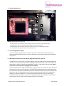
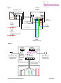
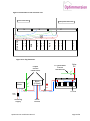
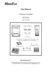
Installation Manual
The system should only be installed by a suitably qualified person.
It is recommended you read these instructions before you begin the installation, but in summary:
Assess the existing electrical wiring to make sure that it is suitable for the installation of a
Optimmersion system.
Mount the power throttle in a suitable location.
Mount the controller in its chosen location.
Install the associated cables and make connections as per figures 1 to 5. (Do not clip on the
current transformers yet.)
Electrically test the circuitry and then energize the system.
Carry out the commissioning steps as described in section (f) below.
General information
Optimmersion measures how much power is flowing through the electricity meter using a current
transformer which clips around the live wire of the feed from the Grid. When there are more than 50
watts being exported, it brings up the immersion heater (water heater), always adjusting the exact
level so as to maintain the exported power below about 200 Watts. Electric appliances can be turned
on and off in the house and Optimmersion makes the appropriate adjustment. Optimmersion also
measures the amount of power being generated by the PV installation using a second clip-on current
transformer. This information is displayed, but has no effect on the control of the water-heater.
Optimmersion incorporates the display within the controller unit itself which is normally installed near
to the consumer unit. This is often in an inconvenient position for seeing the display.
What’s in the box?
The kit that you have received should contain the following components:
1 x controller unit
1 x power throttle
2 x CT clips with phono plug terminations
1 x phono plug to open wire ended control signal cable
1 x power plug to open wire ended power supply cable
1 x length of 5-core 1.5mm cable
PVC cable glands
Please identify each of these components. Call 02032860896 if there is a discrepancy.
You will also need screws and the appropriate wall fixings.
Optimmersion Installation Manual
Page 2 of 8
Installation steps
1. Inspection
Assess the existing immersion heater circuit to ensure that it is a dedicated radial circuit fed
directly from the consumer unit. Any other equipment which is also connected to this circuit must
be disconnected and re-wired.
We recommend that the controller and associated AC circuitry is protected by a 30 mA RCD. Our
chosen modular design allows the controller unit to be mounted away from the consumer unit in a
more convenient position so that the display can be seen at a glance with ease.
The power throttle should be installed adjacent to the property’s main consumer unit, incoming
electrical supply, and the point at which the PV plant’s dedicated supply circuit connects to the
consumer unit.
2. Power throttle
Warning: the power throttle may run hot at times! Mount the unit on a non-flammable
vertical surface and make sure that air is free to run through the vents. If in doubt, we recommend
spacing the power throttle from the wall surface by 10 mm.
3. Controller unit
Remove the lid by gently pressing in the centre of the upper side of the base. The cover will
release from the top, hinging at the bottom. Refit the lid by aligning the two locators at the
bottom, gently pushing home at the top.
Mount the controller unit carefully on a flat surface so as not to distort the enclosure. Failure to do
this may result in damage to the unit and poor fitting of the cover.
The cable entry slot is designed to allow the power and phono cables to be threaded through from
the rear or from the bottom. The plugs may be inserted into their respective sockets prior to final
fixing. We recommend that you first prepare and loosely fix the unit to the wall, and then, before
tightening the fixings, thread the plugs through the cable entry slot and insert them into their
respective sockets, starting at the top and working down.
Optimmersion Installation Manual
Page 3 of 8
4. Socket designations:
E
F
G
H
Figure 1 showing the controller unit.
E: Optimmersion low-voltage AC power supply input from the power throttle (underneath)
F: Socket for the clip-on current transformer which monitors the PV output
G: Socket for the clip-on transformer which monitors the current at the electricity meter
H: Low-voltage control signal output to the power throttle.
5. Low-voltage power supply
Insert the supply lead plug end into socket E and connect the free ends to the AC O/P screw
terminals within the power throttle, as shown in Figures 2 and 3. These may be connected either
way around.
6. Wiring & Connections (see the wiring diagrams Figures 2, 3 and 4)
A length of 5-core 1.5mm cable is provided together with PVC cable glands. Use this between the
consumer unit and the power throttle, intercepting the dedicated water heater circuit. Make the
connections as shown in the two wiring diagrams, Figures 2, 3 and 4 below. At this stage, please
leave both current transformers plugged in but unclipped.
British standard BS 7671: 2008 (amended 2011), regulation 537.3.2.1, allows the circuit-breaker in
the consumer unit to act as the means for switching off the Optimmersion and associated circuits
for maintenance purposes provided that you mount the power throttle near by the consumer unit.
However, if you are mounting the power throttle some way away from the circuit-breaker (for
example, in another cupboard or in a room away from the consumer unit), you will need to
provide a double-pole isolation switch next to the power throttle as an means for local isolation.
Alternatively, you can install a means of locking off the circuit-breaker.
Optimmersion Installation Manual
Page 4 of 8
Figure 2
power
throttle
controller unit
E
F
SIGNAL
5V + 0
AC O/P
G
H
connect either
way around
(not used)
LNENL
centre +
screen/outer 0
power supply
cable
supply
input
water
heater
control cable
PV
output
LNE
from
consumer unit
Figure 3
SIGNAL
AC O/P
0
5V +
outer
control unit
L OUT
N OUT
Earth
L IN
power supply plug
to SolarCache+
connect
either way
around
N IN
centre
phono plug to
SolarCache+
control unit
power
throttle
5 core 1.5 mm cable
consumer unit
L supply from
water heater MCB
N supply
EARTH
N water heater
L water heater
Optimmersion Installation Manual
Page 5 of 8
Figure 4: Connections in the consumer unit
5 core 1.5 mm cable
Existing water heater cable
MCB
MCB
MCB
RCB
MCB WH
E
MCB
MCB
RCB
MCB
N
MCB
MCB
Main switch
N
Figure 5: CT clip placement.
Solar
PV
PV generation
current
transformer
Export
current
transformer
CT
yes
Main
fuse
Incoming
supply
MCB
MCB
MCB
RCB
MCB WH
MCB
E
MCB
MCB
N
RCB
MCB
Meter
Main switch
Block
(if fitted)
MCB
N
no
CT
CT
PV MCB
Other
circuits
Optimmersion Installation Manual
Page 6 of 8
Commissioning
Check that all AC electrical connections are complete and ready for energizing. Carry out appropriate
electrical tests of your wiring, according to BS7671:2008 (amended 2011).
Switch on the immersion heater MCB in the consumer unit and the power throttle DP isolation switch
(if fitted) to energize the system.
Slide the slider function switch, located on the top of the controller unit to the mid position. The
legend “Heat: automatic” should appear in green at the bottom of the display. If instead the legend
“Heat: 1-hr boost” appears, slide the switch to the left and then to the centre.
Make sure that the PV system is switched on and generating power. Clip the PV current transformer
around the PV supply live wire. (Please refer to Figure 5 for correct placement.) Take care to ensure
that the magnet surfaces are clean and engage properly. After a few seconds, the yellow ‘Sun’ display
should indicate the value of the power currently being generated by the PV plant. If the display reads
zero, the current transformer needs to be unclipped and reversed so that the live wire feeds through
from the other direction. (Note that the ‘Sun:’ display alternates every 6 seconds with the ‘Gen:’
display. The yellow bar, however, always shows how much power is being generated.)
Clip the electricity supply input current transformer (the export current transformer in Figure 5)
around the live wire of the incoming electricity supply cable, between the supply cut-out fuse and the
electricity meter, or between the electricity meter and the consumer unit (again ensuring that both
magnet surfaces fully engage). If the PV system is generating more power than the house uses, the
‘Net’ display value will be green after a short time (allow up to a minute) indicating that power is being
exported. If the house usage is greater than the generated power, then the ‘Net’ display value will be
shown in red.
You can check that this current transformer is correctly installed by turning on a high power appliance,
such as an electric kettle. The ‘Net’ display figure should increase and appear in red as power is being
imported from the grid. If the opposite happens (i.e. the Net display goes down, or turns green), then
the current transformer requires reversing so that the live wire feeds through from the other
direction.
Three-position slider function switch
The three-position switch is located on the top right-hand side of the controller or on the top righthand side the remote Blue Tooth display unit. It is a slide switch and operates as follows:
Left position: the heater is fully on, and Optimmersion has no effect. The legend Heat: continuous
appears in red at the bottom of the display, and the blue “Control:” bar should be at full length.
Optimmersion Installation Manual
Page 7 of 8
Mid position: the heater is controlled automatically by Optimmersion. The
legend Heat: automatic or Heat: 1-hr boost (see below) appears in green (or yellow) at the bottom of
the display. This is the normal position.
Right position: the heater is controlled automatically by Optimmersion. However, the heater is turned
fully on between 2 am and 5 am (approximately) under the control of the internal clock.
Note that this clock sets itself automatically to solar time after the first sunset-sunrise, or sunrisesunset sequence, after switching on Optimmersion. The accuracy depends on the weather, time of
year, and other factors, but the clock should be correct within about an hour of GMT (one hour behind
BST). This switch setting is intended for Economy 7 users and should not be used for the first 24 hours
or so after switching on. The legend Heat: auto/night appears in yellow at the bottom of the display.
The number of hours (0 to 24) until the next night boost is also displayed after the Control: legend. The
user can use this to check that the clock has set itself correctly. The legend changes to Heat: eco7
boost during the boost period, and the blue Control: bar should be at full length.
Mid-left-mid movement: if the switch is moved from the mid position to the left position and then
back to the mid position, the heater is turned fully on for 1 hour. This is useful for all-electric systems
to boost the heat. Repeat the process to cancel this function. During the boost period, the legend
Heat: 1-hr boost will appear in yellow at the bottom of the display, and the blue Control: bar should be
at full length.
Optimmersion is sold for professional use and installation.
Technical Specifications and Support
Power consumption of controller
Transfer effi ciency of throttle
Max. load current surge (Amp)
Max. load constant surge
Mains frequency tolerance 50Hz
Operating temperature
Maximum power dissipation at 3kW output
2 watts
98 %
Half a cycle 250, Low repetitive 25
17 amp
+/- 1Hz
65 oC operational
588 watts
Internal fuse
Packaged weight
Packaged dimensions (cm)
20 Amps, 1% ceramic
3.4 kg
L:34 W:27 H:19
If you have any questions regarding the installation or operation of the Optimmersion system, visit our
support site: www.energeno.com/uk/support.
Energeno Ltd.
4th Floor
70-74 City Road
London
EC1Y 2BJ
www.energeno.com
OMM-ENG 1.1 02-13
Optimmersion Installation Manual
Page 8 of 8