1
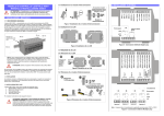
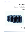
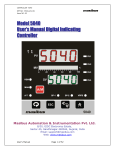
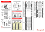
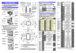
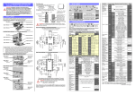
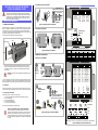
1.3.1 Installing an Interconnect Module RLY 3 (N/O) RLY 2 (N/O) RLY 3 (COM) RLY 2 (COM) RLY 1 (N/O) RLY 1 (COM) SSR3/LIN (-) SSR3/LIN (+) Figure 1 Installing an Interconnect Module 1.1 GENERAL DESCRIPTION The MLC 9000+ System - comprising one or more Bus Modules each with up to eight Loop Modules - is designed for installation in an enclosure which is sealed against the ingress of dust and moisture. The enclosure must contain sufficient length of 35mm Top-Hat DIN mounting rail to accommodate the system modules (see below) plus an extra 50mm of rail to permit modules to be separated for removal/replacement. The space required by the MLC 9000+ modules is shown below. 1.3.2 Installing a Loop Module Thermocouple Heater Break input (Z1301 only) RTD Quick-Release Plunger mV/V mA 120mm 27 26 25 24 23 22 22mm 30mm SSR2 (-) Interconnect Modules 1. INSTALLATION - MECHNICAL DIN Rail Clamp 1 2 3 4 5 6 DIN Rail SSR2 (+) Click! personnel. It is the responsibility of the installing engineer to ensure that the configuration is safe. Local regulations regarding electrical installation & safety must be observed - e.g. US National Electrical Code (NEC) and/or Canadian Electrical Code. Impairment of protection will occur if the product is used in a manner not specified by the manufacturer. SSR1 (-) CAUTION: Installation should be only performed by technically competent 10 11 12 13 14 15 2. INSTALLATION - ELECTRICAL Slide Interconnect BCM Modules to the left until the module is connected to its neighbour SSR1 (+) MLC 9000+ LOOP CONTROLLER MODULE INSTALLATION MANUAL 59326-3 Clamp Figure 5 - Single Loop Electrical Connections 1.3 INSTALLING A LOOP MODULE The MLC 9000+ system is installed in the following order: 1. Bus Communications Module (refer to Bus Module installation instructions) 2. Interconnect Module(s) 3. First Loop Controller Module 4. Second Loop Controller Module 5. Third Loop Controller Module etc…… 5 Relay SSR Relay Relay SSR Relay SSR6 (+) or RLY6 (N/O) SSR6 (-) or RLY6 (COM) SSR5 (+) or RLY5 (N/O) SSR5 (-) or RLY5 (COM) Heater Current Thermocouple To install the Loop Module follow the instructions below: RTD mV/V Figure 4 Removing an Interconnect Module 18 17 16 21 20 19 24 23 22 mA 27 26 25 CAUTION: HOT SWAPPING OF LOOP CONTROLLER MODULES. Although hot swapping of Loop Modules is possible, caution must be exercised in order to eliminate the risk of receiving an electric shock due to the possibility of up to 240VAC being present at the relay terminals of an Loop Module. Before removing any connectors from a Loop Module, please ensure that all hazardous voltages have been isolated from the appropriate connectors. 6 Relay SSR Relay Relay SSR Relay Input 4 or Heater Current Input DIN Rail Slide Interconnect Modules to the right until required Module is disconnected from its neighbours SSR4 (+) or RLY4 (N/O) SSR3 (+) or RLY3 (N/O) Input 2 Input 1 BCM Remove Associated Loop Module 27 26 25 24 23 22 Under normal circumstances, no forced ventilation is required and the enclosure need not contain ventilation slots, but temperatures within the enclosure must be within specification. 4 Relay SSR Relay Relay SSR SSR Input 3 1.2 VENTILATION SSR3 (-) or RLY3 (COM) 1.4.1 Removing an Interconnect Module SSR2 (+) or RLY2 (N/O) Figure 3 Removing a Loop Module It is recommended that (a) some means of preventing unauthorised access to the enclosure interior (e.g. lockable doors) is provided, and (b) that a suitable DIN rail clamp be used, once the MLC 9000+ system is fully installed, to prevent the system from moving on the DIN rail. SSR2 (-) or RLY2 (COM) Press Plunger SSR1 (+) or RLY1 (N/O) WARNING: The maximum of eight Loop Module’s per Bus Module must not be exceeded. Unplug all connectors from top & bottom of the Loop Module SSR1 (-) or RLY1 (COM) NOTE: An additional 60mm of space is required above and below the system modules to permit ventilation and to accommodate wiring bend radii to enclosure trunking or conduits. Allow sufficient slack in all cables inside the trunking to permit “hot” swapping of modules (i.e. modules to be removed/replaced whilst the system is under power). 3 Relay SSR SSR Relay SSR SSR 1 2 3 4 5 6 1.4.1 Removing a Loop Module 2 Relay SSR SSR Relay SSR SSR 10 11 12 13 14 15 1.4 REMOVING A LOOP MODULE Outputs 1 Relay SSR SSR Relay SSR SSR SSR4 (-) or RLY4 (COM) 100mm Module Type Z3611 Z3621 Z3651 Z4610 Z4620 Z4660 21 20 19 18 17 16 Figure 2 Installing a Loop Module Input 3 Input 2 Input 1 Input 4 Note: Heater current input is only applicable to module variants Z3611, Z3621 and Z3651 Figure 6 - Multiple Loop Electrical Connections 2.1 Installation Considerations Ignition transformers, arc welders, mechanical contact relays and solenoids are all common sources of electrical noise in an industrial environment and therefore the following guidelines MUST be followed. 1. If the instrument is being installed in existing equipment, the wiring in the area should be checked to ensure that good wiring practices have been followed. 2. Noise-generating devices such as those listed should be mounted in a separate enclosure. If this is not possible, separate them from the instrument, by the largest distance possible. 3. If possible, eliminate mechanical contact relays and replace with solid-state relays. If a mechanical relay being powered by an output of this instrument cannot be replaced, a solid-state relay can be used to isolate the instrument. 4. Do not run signaling cables adjacent to power-carrying conductors. If the wiring is run in a conduit, use a separate conduit for the signal wiring. Use of shielded cable is recommended and this must be grounded at one point only. Measurement Accuracy Linearisation Accuracy Temperature Stability Lead Compensation RTD Sensor Current PT100 Calibration MLC 9000+ Heater Current Terminals Current Transformer Main conductors to Heaters From power control device Measurement Accuracy Temperature Stability Input Resistance 2.2 Noise Suppression at Source Usually when good wiring practices are followed, no further noise protection is necessary. Sometimes in severe electrical environments, the amount of noise is so great that it has to be suppressed at source. Many manufacturers of relays, contactors etc supply 'surge suppressors' which mount on the noise source. For those devices that do not have surge suppressors supplied, Resistance-Capacitance (RC) networks and/or Metal Oxide Varistors (MOV) may be added. Inductive coils - MOVs are recommended for transient suppression in inductive coils, connected in parallel and as close as possible to the coil. Additional protection may be provided by adding an RC network across the MOV. Contacts - Arcing may occur across contacts when they contact open and close. This results in electrical noise as well as damage to the contacts. Connecting a properly sized RC network can eliminate this arc. For circuits up to 3 amps, a combination of a 47 ohm resistor and 0.1 microfarad capacitor (1000 volts) is recommended. For circuits from 3 to 5 amps, connect two of these in parallel. 2.3 Thermocouple Inputs The correct type of extension leadwire/compensation cable must be used for the entire distance between the Loop Module connector and the thermocouple; correct polarity must be observed throughout and joints in the cable should be avoided. If the thermocouple is grounded, this must be done at one point only. If the thermocouple extension leadwire is shielded, this shield must also be grounded at one point only. 2.4 RTD Inputs The extension leads should be of copper and the resistance of the wires connecting the resistance element should not exceed 50per lead (the leads should be of equal resistance). For three wire RTDs, connect the resistive leg and the common legs of the RTD as illustrated. For a two wire RTD a wire link should be used in place of the third wire. Two wire RTDs should only be used when the leads are less than 3 metres long. Avoid cable joints. 2.5 Heater Current Input For single loop modules with a heater current input the main heater conductor should be passed through a current transformer (CT) the secondary should then be connected to the input terminals of the Loop Module. A value of CT should be selected so that the secondary has a maximum current value of 50mA. For multiple loop modules with a heater current input a single CT is used. Each of the main heater conductors is passed through the single CT. The value of CT needs to be calculated to be able to withstand the maximum current in all three conductors at the same time. If a CT can not be found that is of sufficient size then one of the conductors can be passed through the CT in the opposite direction to the other two this has the effect of cancelling out one of the other conductors and as such reducing the secondary current. Current Transformers available from your local supplier: 25:0.05 50:0.05 100:0.05 part number 85258 part number 85259 part number 85260 Figure 7 3. LOOP MODULE SPECIFICATIONS GENERAL Function Each Loop Module performs the control functions and provides the input and output connections for its own control loops. Up to 4 universal process inputs and up to 6 outputs. (dependent on model variant) Types Available Z1200: One Universal input, two SSR/relay outputs (selectable) Z1300: One Universal input, two SSR/relay outputs and one Linear output or three SSR/relay outputs (selectable) Z1301: One Universal input, one Heater Break input, two SSR/relay outputs and one Linear or three SSR/relay outputs (selectable) Z3611: Three Universal inputs, one Heater Break input, six relay outputs Z3621: Three Universal inputs, one Heater Break input, six SSR outputs Z3651: Three Universal inputs, one Heater Break input, three SSR outputs and three Relay outputs Z4610: Four Universal inputs, six relay outputs Z4620: Four Universal inputs, six SSR outputs Z4660: Four Universal inputs, four SSR outputs and two Relay outputs Process input Type and scale user selectable (see Process inputs table) Sample rate = 10 per second (100ms) Heater Current Measures a Heater current value via an external CT for use by Input the Heater Break Alarm function. PROCESS INPUTS Types available (Range Minimum – Range Maximum) Thermocouple B (100 – 1824°C) B (212 – 3315°F) J (-200.1 – 1200.3°C) J (-328.2 – 2192.5°F) K (-240.1 – 1372.9°C) K (-400.2 – 2503.2°F) L (-0.1 – 761.4°C) L (31.8 – 1402.5°F) E (-250 – 999°C) E (-418 – 1830°F) Measurement Accuracy Linearisation Accuracy CJC Sensor Resistance Influence Thermocouple Calibration N (0.0 – 1399.6°C) N (32.0 – 2551.3°F) R (0 – 1759°C) R (32 – 3198°F) S (0 – 1759°C) S (32 – 3198°F) T (-240.0 – 400.5°C) T (-400.0 – 752.9°F) RTD PT100 (-199.9 – 800.3°C) PT100 (-327.3 – 1472.5°F) NI 120 (-80.0 – 240.0°C) NI 120 (-112.0 – 464.0°F) DC Linear 0 – 20mA 4 – 20mA 0 – 50mV 10 – 50mV 0 – 5V 1 – 5V 0 – 10V 2 – 10V THERMOCOUPLE INPUTS Better than ±0.1% of range span ±1 LSD. Note: Reduced performance with Type “B” thermocouple between 100 – 600°C (212 – 1112°F). Type “T” accuracy is ±0.5% below 100°C Better than ±0.2°C any point, for 0.1°C resolution ranges (0.05°C typical) Better than ±0.5°C any point, for 1°C resolution ranges. Better than ±1C over operating temperature range. <10Ω: as measured accuracy 100Ω: <0.1% of range span error 1000Ω: <0.5% of range span error Complies with BS4937, NBS125 & IEC584 Maximum Resolution RTD INPUTS ±0.1% of range span ±1 LSD for single Loop Modules ±0.2% of range span ±1 LSD for multiple Loop Modules Better than ±0.2°C any point (0.05°C typical) 0.01% of range span/°C change in ambient temperature. Automatic to 50Ω maximum lead resistance, giving less than 0.5% of span additional error. 150µA ±10µA Complies with BS1904 & DIN43760 (0.00385Ω/Ω/°C) DC LINEAR INPUTS Better than ±0.1% of programmed range span ±1 LSD. 0.01% of range span/°C change in ambient temperature mV Input: >1MΩ V Input: 47kΩ mA Input:4.7Ω -32000 to 32000. Equivalent to a 16-bit ADC HEATER CURRENT INPUT (Z1301, Z3611, Z3621 and Z3651 only) Input Sampling Delta-sigma at 1kHz Method Input Resolution 8 bits over 250mseconds rolling window Accuracy Better than ±2% of span Isolation Via external current transformer Internal Burden 15Ω Input Span 0 – 60mA rms. (assuming sinusoidal input current waveform) Range Maximum Adjustable 0.1A to 1000.0A Range Minimum Fixed at 0A Contact Type Rating Lifetime Drive Capability Isolation Resolution Accuracy Update Rate Drive Capability Isolation Ambient Temperature Relative Humidity Supply Voltage Altitude EMC Standard Safety Dimensions Mounting Connector Types Weight RELAY OUTPUTS Single pole single throw (SPST) Normally open contacts (N/O) 2A resistive @ 120/240VAC >500,000 operations at rated voltage/current SSR DRIVE OUTPUTS 12V DC nominal (10V DC minimum) at up to 20mA load Isolated from process input and relay outputs. Not isolated from each other or linear outputs. Not isolated from other similar outputs in the same system. LINEAR OUTPUT Eight bits in 250ms (10 bits in 1 second typical) ±0.25% (mA into 250Ω load, V into 2kΩ load) Degrading linearly to ±0.5% for increasing burden to maximum drive capability. 10 samples per second 0-20mA: 500Ω maximum load 4-20mA: 500Ω maximum load 0-5V: 500Ω minimum load 0-10V: 500Ω minimum load Isolated from process input and relay outputs. Not isolated from SSR Drive outputs or other similar outputs in the same system OPERATING CONDITIONS 0°C to 50°C (operating); -20°C to 80°C (storage) 30% - 90% non-condensing (operating and storage) Powered by Bus Module within its operating conditions <2000m EN61326-1. Complies with EN61010-1 and UL 3121-1. Pollution Degree 2, Installation Category II. Indoor use only PHYSICAL Height: - 100mm; Width: - 22mm; Depth: - 120mm 35mm x 7.5mm Top Hat DIN rail mounting via Interconnect Module (EN50022, DIN46277-3) All 5.08mm Combicon type, Minimum cable rating 87°C 0.15kg