1
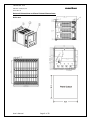
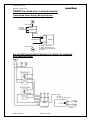
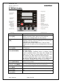
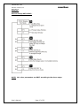
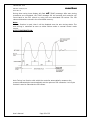
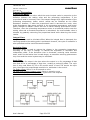
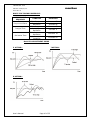
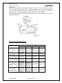
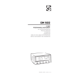
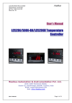
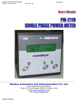
CONTROLLER -5040
masibus
REF NO: m53A/om/101
Issue NO: 02
Model 5040
User’s Manual Digital Indicating
Controller
Masibus Automation & Instrumentation Pvt. Ltd.
B/30, GIDC Electronics Estate,
Sector-25, Gandhinagar-382044, Gujarat, India
Email: [email protected]
Web: www.masibus.com
User’s Manual
Page 1 of 52
CONTROLLER -5040
masibus
REF NO: m53A/om/101
Issue NO: 02
Contents
(1)
Introduction…………………………………………………………………… (03)
(2)
Installation…………………………………………………………………….. (05)
(3)
Hardware Specification Detail………………………………………….. (08)
(4)
Wiring Diagram………………………………………………………………. (13)
(5)
Front Panel Description……………………………………………………. (15)
(6)
Menu Layout………………………………………………………………….. (18)
(7)
Parameter Flow Chart……………………………………………………… (30)
(8)
Alarm Logics and Digital Outputs……………………………………… (32)
(9)
Digital Inputs…………………………………………………………………. (36)
(10)
Control Function Description……………………………………………. (37)
(11)
Calibration Procedure……………………………………………………… (43)
(12)
Modbus Communication Detail…………………………………………. (46)
(13)
Miscellaneous…………………………………………………………………. (50)
User’s Manual
Page 2 of 52
CONTROLLER -5040
masibus
REF NO: m53A/om/101
Issue NO: 02
1. INTRODUCTION:
Fo r ew o rd
Th an k y ou f o r p u r ch asi n g 5 0 4 0 s e ri e s P ID c on t r ol l er . Th i s m an u al
d e s c ri b e s t h e b asi c fu n ct i on s an d op e rat i on m et h od s o f 5 0 4 0 . Pl ea s e
r ea d t h r ou g h t h i s u s e r ’s m an u al ca r e fu l ly b ef o r e u si n g t h e p r od u ct .
No t ic e
Th e c on t en t s of t h i s m an u al a r e su b j e ct t o ch an g e wi t h ou t n ot i c e as a
r e su l t o f c on t i n u i n g i m p r ov e m en t s t o t h e i n st ru m en t ’s p e rf o rm an ce an d
fu n ct i on s
Every effort has been made to ensure accuracy in the preparation of this
manual. Should any errors or omissions come to your attention, however, please
inform MASIBUS Sales office or sales representative. Under no circumstances may
the contents of this manual, in part or in whole, be transcribed or copied without our
permission.
Trademarks
Our product names or brand names
mentioned in this manual are the
trademarks or registered trademarks of Masibus Automation and Instrumentation (P)
Ltd. (herein after referred to as MASIBUS).
Adobe, Acrobat, and Postscript are either registered trademarks or trademarks of
Adobe Systems Incorporated. All other product names mentioned in this user's
manual are trademarks or registered trademarks of their respective companies.
Re v is i on
1st Edition: March 2010.
User’s Manual
Page 3 of 52
CONTROLLER -5040
masibus
REF NO: m53A/om/101
Issue NO: 02
Ch ec k i n g t he Co nt en ts of t h e P ac k ag e
U n p ack t h e b ox an d ch e ck t h e con t en t s b e f or e u si n g t h e
p r od u ct . If t h e p r o d u ct i s d i f f e r en t f r o m t h at wh i ch you h av e o rd e r ed ,
i f an y p a rt s o r a c c e s so ri es a r e m i s si n g , o r i f t h e p r od u ct a p p e a r s t o b e
d am a g ed , c on t act y ou r s al e s r ep r e s en t at i ve .
Product Ordering Code:
The Single Loop Controller unit has a nameplate affixed to the top of the
terminals. Check the model and suffix codes inscribed on the nameplate to confirm
that the product received is that which was ordered.
Model
Suffix code
Optional code
Remarks
List of Accessories
The product is provided with the following accessories according to the model
and suffix codes (see the table below). Check that none of them are missing or
damaged.
No
Item
name
Part
number
User’s Manual
Qty
Remarks
Page 4 of 52
CONTROLLER -5040
masibus
REF NO: m53A/om/101
Issue NO: 02
2. Installation:
How to Install:
Mounting method: Panel mounting
To install the controller select a location where:
o
o
o
o
o
o
o
o
o
no one may accidentally touch the terminals
mechanical vibrations are minimal
corrosive gas is minimal
temperature can be maintained at about 25˚C to 35˚C and the
fluctuation is minimal
no direct radiant heat is present
no magnetic disturbances are caused
no wind blows against the terminal board
no water splashed
no flammable materials are around
Turn off the power to the controller before installing it on the
panel because there is a possibility of electric shock
User’s Manual
Page 5 of 52
CONTROLLER -5040
masibus
REF NO: m53A/om/101
Issue NO: 02
External Dimensions and Panel Cutout Dimensions:
Unit: mm
User’s Manual
Page 6 of 52
CONTROLLER -5040
masibus
REF NO: m53A/om/101
Issue NO: 02
How to connect wires:
Before carrying out wiring, turn off the power to the
controller and check that the cables to be connected are not alive with
a tester or the like because there is a possibility of electric shock.
NOTE:
o
o
o
o
o
All wiring must confirm to appropriate standards of good practice and
local codes and regulations. Wiring must be suitable for Voltage,
Current and temperature rating of the system.
Provide power from a single-phase instrument power supply. If there
is a lot of noise in the power line, insert an insulating transformer into
the primary side of the line and use a line filter on the secondary side.
Do not place the primary and secondary power cables close to each
other.
For thermocouple input, use shielded compensating lead wires for
wiring. For RTD input, use shielded wires that have low conductor
resistance and cause no significant differences in resistance between
the three wires. Do not connect Terminal – 23 when thermocouple or
Linear input is selected.
Use repeater after each set of 32 instruments connected in RS-485
Communication.
Unused terminals should not be used as jumper points as they may be
internally connected, which may cause damage to the unit.
CAUTION:
High voltage transients may occur when switching inductive loads such
as some contactors or solenoid valves. Through the internal contacts,
these transients may introduce disturbances which could affect the
performance of the instrument.
For this type of load it is highly recommended that a “sunbber” is
connected across the normally open contact of the relay switching
through load. The sunbber recommended consists of a series
connected resistor/capacitor (typically 15nF/100Ohms). A sunbber will
also prolong the life of the relay contacts. A sunbber should also be
connected across the output of a tric output to prevent false triggering
under line transient conditions.
User’s Manual
Page 7 of 52
CONTROLLER -5040
masibus
REF NO: m53A/om/101
Issue NO: 02
3. Hardware Specification Detail:
Input type: Universal input type
Thermocouple, RTD, Millivolt, Voltage, Current INPUT types are software selectable.
Applicable Standards: DIN (ITS-90) for Thermocouple and RTD
T yp e
R an g e
E
- 2 0 0 t o 1 0 0 0° C
J
- 2 0 0 t o 1 2 0 0° C
K
- 2 0 0 t o 1 3 7 0° C
T
-200 to 400°C
B
4 5 0 t o 1 8 0 0° C
R
0 t o 1 7 5 0 °C
S
0 t o 1 7 5 0 °C
N
-200 to 1300°C
RTD
- 1 9 9 .9 t o
8 5 0 .0 °C
Ac cu r a cy
+0.1% of instrument range
+ 1 digit for temperature
equal to or higher than 0º C
+ 0.25% of instrument
range + 1 digit for
temperature
below 0º C
Re s ol ut i on
0 .1 °C
+0.25% of instrument range
+ 1 digit(B,R,S TYPE TC)
+ 0 .1 % o f i n st ru m e n t
ran g e + 1 d i g i t
0 to 75mV
0 to 100mv
0 .4 t o 2 V
0 to 2V
0-20 mA*
4-20 mA*
-1999 to 9999
0 to 5V
1 to 5V
1 C ou n t
+ 0 .1 % o f i n st ru m e n t
ran g e + 1 d i g i t
0 to 10V
-10 to
20mV
*For DC current input, 100 Ohms (0.1%, 25 ppm) shunt resistor must be connected
externally. For DC current and Voltage input, Scaling is possible and decimal point is
selectable.
Sampling Period: 250mSeconds.
Resolution: 17-bit
Burnout detection: Functions for TC, RTD, linear input signal. (It detects whether
sensor is connected or not) Control output or Alarm output can be selected for
sensor error condition.
Measurement current (RTD): About 1milli Ampere
Input Impedance:
User’s Manual
>1 Mohm for thermocouple/ mV/RTD/Volts inputs
Page 8 of 52
CONTROLLER -5040
masibus
REF NO: m53A/om/101
Issue NO: 02
Noise Rejection Ratio:
NMRR (Normal mode rejection ratio) > 40 dB (50/60 Hz) or more
CMRR (Common mode rejection ratio) > 120 dB (50/60 Hz) or more
Allowable wiring resistance for RTD: Maximum 15 ohms/wire (Conductor
resistance between three wires should be equal).
Reference Junction Compensation Error: ±2˚C
Remote Input Signals:
Input type: Settable in a range from 0-5 V or 1-5 V DC. The input type can be
selected with the front keypad. For 0 – 20mamp (0-5v) and 4 – 20mamp (1-5v)
250ohms (0.1%, low ppm) resistor should be connected externally. Input sampling
time for remote input is 3 times the PV input.
Input Range: -1999 to 9999 counts maximum
Resolution: 17-bit
Input resistance: > 1Mohm.
Input accuracy: ±0.1% instrument range, ±1 Count
Feedback Resistance Input:
Slide
resistance
value:
1kohms
to
2Kohms
of
overall
(burnout detection for all the three wires provided)
Measuring resolution: 0.1% of overall resistance (After User’s adjustment).
resistance
Loop Power Supply:
Supply Voltage: 24 ± 1 VDC, 30 mAmp with Inbuilt Short Circuit Protection. When
using 24V DC loop power supply, keep the operating ambient temperature between 0
to 40˚C
Minimum load resistance: 800 ohms
Output Types:
Output types are software selectable from the Key board or Modbus.
• RELAY OUTPUT(PID and ON/OFF control)
•
SSR OUTPUT (Voltage Pulse)
•
LINEAR OUTPUT (4-20mAmp)
•
VALVE POSITION FEEDBACK CONTROL
•
VALVE POSITION WITHOUT FEEDBACK CONTROL
Also, Output Direction (Direct/Reverse) for Heating and Cooling are selectable from
software.
Retransmission Output:
Number of outputs: 1
Process Value, Set point, or Control output can be selected as a Retransmission
output.
Output signal: 0-20 mA, 4-20 mA, 0-5 V, 1-5 V or 0-10 V DC.
Voltage or current output can be selected through software and internal jumper
settings.
Load resistance: 500 ohms Max. Or less for current output. 3k or higher for voltage
output
User’s Manual
Page 9 of 52
CONTROLLER -5040
masibus
REF NO: m53A/om/101
Issue NO: 02
Output accuracy: ±0.25% of span.
Control Output:
Current Output:
Output signal: 4-20 mA
Load resistance: 500 ohms Max. Or less for current output.
Accuracy: ±0.25% of span.
Voltage pulse output:
Output signal: Voltage Pulse
Load resistance: 500 ohms Max. Or more.
Output signal On-voltage: 11 V DC or more.
Off-voltage: 2 V DC or less.
Resolution: 10 ms
Voltage Pulse or current output can be selected through software.
Relay Contact Outputs:
Number of outputs: 1 or 2 (two for forward/reverse motor control
Heating/Forward-side output Cooling/Reverse-side output
Output signal: Three terminals (NC, NO, and C)
Relay Contact rating: 250 V AC or 30 V DC, 2A (resistive load)
Resolution: 10 ms
type)
Alarm Outputs:
Number of Outputs: 2 if control output (Linear or Voltage Pulse) used for controlling,
the two control relays are available as alarm outputs
Output signal: Three terminals (NC, NO, and C)
Purpose: Alarm output and others. (See Alarm and Digital outputs function)
Relay contact rating: 250 V AC or 30 V DC, 2A (resistive load).
Contact Digital Outputs:
Number of outputs: 4
Purpose: Various Alarm outputs such as PV High / Low, PV Input OPEN, RSP Input
OPEN, VPFB Input OPEN and other Fail safe conditions are available.
Output type: Open collector.
Output Contact rating: 24V DC, 50 mA, with inbuilt current limit protection.
Contact Digital Inputs:
Number of inputs: 4
Purpose: Target set point selection, Auto/ Manual selection, Remote/ Local mode
switching and Run/Stop mode selection.
Input type: Non-voltage contact or transistor open collector input
Input contact rating: 24 V DC, 5 mA or more
Minimum status detection Holds time: About 1 Second
Communication:
Communication Type: Half duplex/Asynchronous (RS-485)
Communication Protocol: MODBUS RTU
Baud rate, Parity and Stop bit are selectable form the key board.
All parameters are Configurable through MODBUS.
Connectable number of unit: 32
Communication error Detection: CRC Check
User’s Manual
Page 10 of 52
CONTROLLER -5040
masibus
REF NO: m53A/om/101
Issue NO: 02
Display Specifications:
PV display: 4-digits, 7-segment, Red LEDs, character height of 0.56’’
Set point display: 4-digits, 7-segment, Green LEDs, character height of 0.4’’
Ba r Di sp l ay : 20 Orange LEDs for %POWER, Valve position indication
S t at u s i n d i cat i n g l am p s : Red LEDs for RELAY AND Alarm status, Manual mode
status, Remote status. Green LEDs for Communication,Green Leds for Set Point
selection 1 and 2,Auto-tune status Green Led,Valve Position Feedback status Green
Led.
Power Supply Specifications:
Power supply: Rated voltage of 85 to 260V AC (±10%), 50/60 Hz
Rated voltage of 18 to 36V DC (Optional),
Power consumption: Max. 15 VA
Data backup: Non-volatile memory (can be written up to 100000 times)
Withstanding Voltage:
• Between primary terminals* and secondary terminals** at
least 1500VAC for 1 minute
•
Between secondary terminals at least 600V AC for 1 minute
Insulation resistance: 20Mohms or more at 500V DC
* P ri m a ry t e rm i n al s i n d i cat e p ow e r t e rm i n al s a n d r el a y ou t p u t t e rm i n al s
* * S e c on d a r y t e rm i n al s i n d i cat e an al og I / O si g n al s , v ol t ag e p u l se
ou t p u t , C on t a ct i n p u t t e rm i n al s , R e m ot e i n p u t .
Signal Isolations Specifications:
PV input terminals: Not isolated from Feedback slide resistance input terminals and
from the internal circuit. But isolated from other input/output terminals.
Remote input terminals: Isolated from other input/output terminals and the internal
circuit.
24 VDC loop power supply terminals: Not isolated from internal circuit.
Analog output terminals (Voltage/current control output): Not isolated from current
outputs and voltage pulse output. Isolated from other input/output terminals and
internal circuit.
Retransmission output terminals (voltage/current): Not isolated from current or
voltage outputs Isolated from other input/output terminals and internal circuit.
Relay contact control output terminals: Isolated between contact output terminals
and from other Input/output terminals and internal circuit.
Contact input terminals: Isolated from other input/output terminals and internal
circuit.
RS-485 Communication terminals: Isolated from other input/output terminals and
internal circuit
Relay contact output terminals: Isolated between relay contact outputs. Isolated
from other input/output terminals and internal circuit.
Transistors contact output terminals:
Non-isolated between transistor contact
outputs, but isolated from other input/output terminals and other terminals
Feedback slide resistance input terminals: Not isolated from PV input terminals but
isolated from other input/output terminals and from internal circuit.
Power terminals: Isolated from other input/output terminals and internal circuit.
User’s Manual
Page 11 of 52
CONTROLLER -5040
masibus
REF NO: m53A/om/101
Issue NO: 02
Construction, Installation, and Wiring:
Construction: Only the front panel is dust-proof
Material: ABS resin and Polycarbonate
Case color: Black
Weight: About 1 kg or less
Dimensions: 96 (W) x 96 (H) x 110 (depth from panel face) mm.
Installation: Panel-mounting type. With Top and Bottom mounting hardware (1 each)
Panel cutout dimensions: 92.5 + 0.8(W) x 92.5 + 0.8(H) mm
Environmental Conditions:
TEMPCO: FOR PV (Main input) and RSP (Remote input) less than 100ppm. FOR
Retransmission and Control output less than 150ppm.
Humidity: 30% to 95% RH (Non-Condensing)
Instrument Warm-up Time: 30 minutes or more after power on
Ambient temperature: 0 to 55°C
User’s Manual
Page 12 of 52
CONTROLLER -5040
masibus
REF NO: m53A/om/101
Issue NO: 02
4. WIRING DIAGRAM:
BACK PLATE WIRING DETAIL:
User’s Manual
Page 13 of 52
CONTROLLER -5040
masibus
REF NO: m53A/om/101
Issue NO: 02
TRASMITTED POWER SUPPLY WIRING DIAGRAM:
Transmitted Power Supply Wiring Diagram:
TPS +24 VOLT
RTD SENSOR
CONNECTED
TO TRASMISTTER
2-WIRE
TRASMITTER
4-20mAmp
22
100 Ohms 0.1%
PID5040
21
SELECT INPUT TYPE:4-20mAmp
TPS -24 VOLT
SET RANGE HIGH AND RANGE LOW
ACCORDING TO 2-WIRE TRANSMITTER
INPUT SENSOR
VALVE POSITION FEEDBACK WIRING FOR INTERLOCK FORWARD
AND REVERSE RELAY:
User’s Manual
Page 14 of 52
CONTROLLER -5040
masibus
REF NO: m53A/om/101
Issue NO: 02
5. FRONT PANEL:
Name of Part
Process Value
Display(PV)
Set Value Display
(SV)
Control Output Value Bar
Display(MV)
Output Indicator
Lamps(RL1 & RL2)
Alarm
Indicator
Lamps(RL3 & RL4)
Remote/Local Set point
Indicator Lamp(REM)
Manual
Mode
Lamp(MAN)
Communication Indicator
Lamps(T,R)
Auto-Tune
Indicator
Lamps(A-T)
User’s Manual
Function
Displays Process Value.
Display Parameter Name When You Set Parameter.
Displays Error Message When An Error Occurs.
Displays Set Value.
Displays Parameter Value Of Parameter In Process Value
Field When You Set Parameter.
Displays Control Output Value When in Manual Mode.
Display blink SP value and Tune message when auto tune
start
Displays Control Output Value in Form of Bar Scaled in
20 Segments.
In Heat Action, OP1 Lamp will Indicate The On Status Of
The Heat output.
In Valve Position Feedback Action & Without Valve
Position Feedback Action; OP1 Lamp Will Indicate The
Status Of The Heat Or Forward Output And OP2 Lamp
Will Indicate The Status Of Cool Or Reverse Output.
In Control Applications With Linear Control Output They
Will Work As Normal Alarms (Alarm 1 & 2). When Alarm
1 & 2 Occurs, Respective Alarm Lamp Is Lit (In Red).
When Alarm 1 & 2 Occurs, Respective Alarm Lamp (RL3
& RL4) Is Lit (In Red).
It Indicates Whether Remote Set Point Is Selected Or
Not. It Is Lit When Remote Set Point Is Selected.
Indicator Lamp will light when Manual Mode is selected
Indicator Lamps Will light When The Communication Is
On.
Indicator Lamps Will blink When Auto tune Process is on.
Page 15 of 52
CONTROLLER -5040
masibus
REF NO: m53A/om/101
Issue NO: 02
Name of Part
Set Point – 1 (SP-1)
Set Point – 1 (SP-2)
Valve
Position
Feedback(VPFB)
Function
Indicator Lamps Will On When Set Point 1 is selected.
Indicator Lamps Will On When Set Point 1 is selected.
Indicator Lamps Will On When output type is VPFB
selected.
KEY FUNCTION Description:
MENU/ENTER KEY:
It is used to enter in the sub menu (various levels) and save the parameters to
nonvolatile memory, when user setting a proper data by Increment and shift key for
parameter configuration.
ESCAPE KEY:
It is used to come out from any sub menu (various levels) to the run mode.
INCREMENT KEY:
It is used to increment the parameter for selection. Value of parameter can be
incremented by pressing this key. When first time increment key pressed, DP
(decimal point) in SV display blink, so user can modify the value with increment key.
It is used to increment the value in particular digit. Value can be incremented from
0- 9 and from ‘9’ again it rollovers to ‘0’.
SHIFT KEY/DECREMENT Key:
It is used to Shift the digit to set the parameter as describe in increment key when
DP (decimal point) started to blink. Menu key is used to go forward to show next
parameter and Shift key is used to go backward to show previous parameter. Also, in
manual mode control output (%power) can be decrement using Shift key.
AUTO/MANUAL KEY:
It is used to switch between auto to manual mode and manual to auto mode. During
manual mode Increment key is used to increase to power and Shift/Decrement key
is used to decrease the power.
User’s Manual
Page 16 of 52
CONTROLLER -5040
masibus
REF NO: m53A/om/101
Issue NO: 02
Example:
How to change SET POINT:-
NOTE: ALL other parameters can EDIT according to the above steps.
User’s Manual
Page 17 of 52
CONTROLLER -5040
masibus
REF NO: m53A/om/101
Issue NO: 02
6. Menu Layout:
RUN TIME INDICATION:
Following parameters can view or change during run time.
• Press Shift key to show percentage power (0.0 to 100.0%)
•
For Thermocouple input type, Press Inc key to show ambient
temperature.
•
During manual mode, Inc key and Shift key/Decrement Key will use
to modify the percentage power.
•
During manual mode, If VPFB/VPNA output type is selected, Inc key
and Shift key will use to OPEN or CLOSE the Valve.
Se t Po i nt se tt i ng :Pressing MENU key PV Display shows SET.1 (Set.1) message. SV display
shows Set Point Value Use Inc and shift key to modify value. OR press
MENU key again to set value for Set point 2.
Se t Po i nt S et t in g :
Parameter
(PV display)
Symbol
Name
Sp
.1
Ta rg et S et p oi n t - 1
(SP.1)
SP
.2
Ta rg et S et p oi n t - 2
(SP.2)
S et t i n g n a m e an d
d e s c ri p t i on
( S V d i sp l ay)
D ep en d i n g on P V
s en so r t yp e s el ec t e d
D ep en d i n g on P V
s en so r t yp e s el ec t e d
User’s Manual
Page 18 of 52
D ef au l t
val u e
200
300
S h o w s on l y
if
-
CONTROLLER -5040
masibus
REF NO: m53A/om/101
Issue NO: 02
Le ve l – 1 :Pressing MENU key for 3 seconds (approx.) PV Display shows Mode (mode)
message. SV display shows LvL1 (LvL1) Use Inc key to move to other
menu levels. Or Press MENU key again to scroll through the menu items of
Level - 1.
This level allows user to auto tune a process or manually set the PID
values and some other parameters as shown below.
LE VE L 1 : C on tr o l P a r am et e rs Co n f ig u r at io n
Pa ra m et e r
S et t i n g n a m e an d
( PV d i sp l ay )
d e s c ri p t i on
Symbol
Name
(SV display)
D ef au l t
val u e
S h o w s on l y
if
Co n t r ol t yp e
s el e ct ed i s
P ID t yp e
a
.tun
(A.tUn)
Auto tune
Yes/no
Yes no
1:(YES)
0 : ( n o)
no
Pb
(Pb)
Ti
(ti)
Td
(td)
Pr o p or t i on al Ban d
0 .1 t o 9 9 9 . 9
50.0
In t eg ral Ti m e
0 t o 1 0 0 0 s e c on d s
120
D eri v at i v e Ti m e
0 t o 2 5 0 s e c on d s
0
Ct
(Ct)
db
(db)
Pb
.SH
(Pb.SH)
arw
(ARW)
HY
(HY)
Control type is
PID.
1 t o 2 5 0 s e c on d s
10
Co n t r ol t yp e
i s h eat o r
c o ol ,
p o si t i on f/ b ,
wi t h ou t f / b
P ID.
0 .1 t o 5 0 .0
1 .0
Co n t r ol t yp e
i s P ID .
-50.0 to 50.0 %
0%
Co n t r ol t yp e
i s P ID .
A n t i R es e t Wi n d u p
0 to 100%
0%
h ys t e r esi s ( On / O ff
c on t r ol )
1 to 250
2
Cy cl e Ti m e
P osi t i on
Pr o p or t i on al D ead
Ban d
P b an d sh i ft
( O v e rsh o ot
su p p r e s si on )
RAMP
(Ramp)
R a m p R at e t yp e
Rmp
.R
(rmp.r)
R am p rat e val u e
User’s Manual
none/ min.r /hr.r
0:none
1:min.r
2:hr.r
0 .1 t o 9 9 9 . 9 D eg r e e
p e r m i n u t es o r h ou r
Page 19 of 52
Control type is
PID.
Co n t r ol t yp e
i s on / of f
N on e
Control type is
PID
0 .1
Control type is
PID
CONTROLLER -5040
masibus
REF NO: m53A/om/101
Issue NO: 02
LE VE L 2 :Pressing MENU key for 3 seconds (approx.) PV Display shows Mode (mode)
message. SV display shows Lvl2
Lvl2 (LvL2) Use Inc key to move to other
menu levels.
Please refer Alarm / Digital output section for better understanding and
selection of alarm types.
LE VE L 2 : A l a r m A N D D ig it a l O ut p ut S ett i ng s
Pa ra m et e r
S et t i n g n a m e an d
( PV d i sp l ay )
d e s c ri p t i on
( S V d i sp l ay)
Symbol
Name
A l arm 1 S et
A1
.SP
PV r an g e sel ec t ed 1
p oi n t
(A1.SP)
0 t o 1 8 . R ef e r al a rm
A1
.tP
A l arm 1 T yp e
t yp e t a b l e.
(A1.tP)
A l arm 1
A1
.HY
1 to 250
H ys t er e si s
(A1.HY)
norm / flsf
A l arm 1 L o g i c
A1
.lC
( n o rm al o r fai l
0 : ( n o rm )
(A1.LC)
sa f e s el e ct i on )
1: (FLSF)
A1
.dY
A l arm 1 D el a y
1 t o 9 9 s ec on d s
(A1.Dy)
A l arm 2 S et
A2
.SP
PV r an g e sel ec t ed 1
p oi n t
(A2.SP)
0 t o 1 8 . R ef e r al a rm
A2
.tP
A l arm 2 T yp e
t yp e t a b l e.
(A2tP)
A l arm 2
A2
.HY
1 to 250
H ys t er e si s
(A2.HY)
norm / flsf
A l arm 2 L o g i c
A2
.LC
( n o rm al o r fai l
0 : ( n o rm )
(A2.LC)
sa f e s el e ct i on )
1: (FLSF)
A2
.dY
A l arm 2 D el a y
1 t o 9 9 s ec on d s
(A2.Dy)
A l arm 3 S et
A3
.SP
PV r an g e sel ec t ed 1
p oi n t
(A3.SP)
0 t o 1 8 . R ef e r al a rm
A3
.tP
A l arm 3 T yp e
t yp e t a b l e.
(A3.tP)
A l arm 3
A3
.HY
1 to 250
H ys t er e si s
(A3.HY)
1
If the value falls outside the range, output is unpredictable.
User’s Manual
Page 20 of 52
D ef au l t
val u e
0
0 ( n on e)
2
N or m al
1
0
0 ( n o n e)
2
N or m al
1
0
0 ( n o n e)
2
S h o w s on l y
if
CONTROLLER -5040
masibus
REF NO: m53A/om/101
Issue NO: 02
A3
.LC
(A3.LC)
A l arm 3 L o g i c
norm / flsf
0 : ( n o rm )
1 : ( F LS F )
N or m al
A3
.Dy
(A3.Dy)
A4
.SP
(A4.SP)
A4
.tP
(A4.tP)
A4
.HY
(A4.HY)
A l arm 3 D el a y
1 t o 9 9 s ec on d s
1
A l arm 4 S et
p oi n t
PV r an g e sel ec t ed 1
0
A l arm 4 t yp e
0 t o 1 8 . R ef e r al a rm
t yp e t a b l e.
0 ( n o n e)
A l arm 4
H ys t er e si s
1 to 250
2
A4
.LC
(A4.LC)
A l arm 4 L o g i c
norm / flsf
0 : ( n o rm )
1:(FLSF)
N or m al
A4
.Dy
(A4.Dy)
d1
.SP
(d1.SP)
d1
.tP
(d1.tP)
d1
.HY
(d1.HY)
A l arm 4 D el a y
1 t o 9 9 s ec on d s
1
Di g i t al Ou t p u t 1
S et p oi n t
Di g i t al Ou t p u t 1
Ty p e
Di g i t al Ou t p u t 1
H ys t er e si s
PV r an g e sel ec t ed 1
0
0 t o 1 8 . R ef e r al a rm
t yp e t a b l e.
0 ( n o n e)
1 to 250
2
d1
.LC
(d1.LC)
Di g i t al Ou t p u t 1
L og i c
norm / flsf
0 : ( n o rm )
1 : ( F LS F )
N or m al
d1
.dY
(d1.Dy)
d2
.SP
(d2.SP)
d2
.tP
(d2.tP)
d2
.HY
(d2.HY)
Di g i t al Ou t p u t
D el ay
Di g i t al Ou t p u t
S et p oi n t
Di g i t al Ou t p u t
Ty p e
Di g i t al Ou t p u t
H ys t er e si s
1 t o 9 9 s ec on d s
1
2
PV r an g e sel ec t ed 1
0
2
0 t o 1 8 . R ef e r al a rm
t yp e t a b l e.
0 ( n o n e)
1 to 250
2
d2
.LC
(d2.LC)
Di g i t al Ou t p u t 2
L og i c
norm / flsf
0 : ( n o rm )
1 : ( F LS F )
N or m al
d2
.dY
(d2.Dy)
d3
.SP
(d3.SP)
d3
.tP
(d3.tP)
Di g i t al Ou t p u t 2
D el ay
Di g i t al Ou t p u t 3
S et p oi n t
Di g i t al Ou t p u t 3
Ty p e
1 t o 9 9 s ec on d s
1
PV r an g e sel ec t ed 1
0
0 t o 1 8 . R ef e r al a rm
t yp e t a b l e.
0 ( n o n e)
User’s Manual
1
2
Page 21 of 52
CONTROLLER -5040
masibus
REF NO: m53A/om/101
Issue NO: 02
d3
.HY
(d3.HY)
Di g i t al Ou t p u t 3
H ys t er e si s
1 to 250
2
d3
.LC
LC
(d3.LC)
Di g i t al Ou t p u t 3
L og i c
norm / flsf
0 : ( n o rm )
1:(FLSF)
N or m al
d3
.dY
(d3.Dy)
d4
.SP
(d4.SP)
d4
.tP
(d4.tP)
d4
.HY
(d4.HY)
Di g i t al Ou t p u t
D el ay
Di g i t al Ou t p u t
S et p oi n t
Di g i t al Ou t p u t
t yp e
Di g i t al Ou t p u t
H ys t er e si s
1 t o 9 9 s ec on d s
1
4
PV r an g e sel ec t ed 1
0
4
0 t o 1 8 . R ef e r al a rm
t yp e t a b l e.
0 ( n o n e)
1 to 250
2
d4
.LC
(d4.LC)
Di g i t al Ou t p u t 4
L og i c
norm / flsf
0 : ( n o rm )
1 : ( F LS F )
N or m al
d4
.dY
(d4.Dy)
Di g i t al Ou t p u t 4
D el ay
1 t o 9 9 s ec on d s
1
User’s Manual
3
4
Page 22 of 52
CONTROLLER -5040
masibus
REF NO: m53A/om/101
Issue NO: 02
LE VE L : - 3
Pressing MENU key PV for 3 seconds (approx.) Display shows Mode (mode)
message. SV display shows Lvl3
Lvl3 (LvL3) Use Inc key to move to other
menu levels. This level allows user to select input type and some other
parameters as shown below.
LE VE L 3 : F un ct io n a l P a r am et e r s C on fi g ur a t io n P a rt- 1
Pa ra m et e r
S et t i n g n a m e an d
D ef au l t
( PV d i sp l ay )
d e s c ri p t i on
val u e
( S V d i sp l ay)
Symbol
Name
PV In p u t Ty p e
inP
.t
F ol l ow T ab l e 1
K - TC
( E , J , K , T et c.)
(inP.t)
Yes/no
A u t o C ol d
A
.CJ
CJC
j u n ct i on
1:(YES)
Y ES
(A.CJC)
Co m p en sat i on
0 : ( n o)
F i x c ol d j u n c t i on
FCJC
.
0 .0
0 to 60.0 Degree
Co m p en sat i on
(F.CJC)
R an g e of t h e s en s o r /
Pr o c e s s val u e
-1999 to 9999
ran g e h i g h
Pv
.Hi
( f o r l i n ea r i n p u t
1370
s et t i n g
(Pv.Hi)
t yp e s)
( sp an > Z e r o)
Pv
.Lo
(Pv.Lo)
Dp
(dP)
ot
(oT)
Co
.Hi
(Co.Hi)
Co
.Lo
(Co.Lo)
PV
.SC
SC
.
(PV.SC.)
Pr o c e s s val u e
ran g e l o w e r
s et t i n g
D eci m al P oi n t
S et t i n g
Ou t p u t T yp e
Co n t r ol Ou t p u t
h i g h l i mi t ( h i >
l o)
Co n t r ol Ou t p u t
l ow l i m i t
Pr o c e s s val u e
s cal e
User’s Manual
S h o w s on l y
if
In p u t s en s o r
i s T/ c . t y p e
In p u t s en s o r
i s T/ c . t y p e
-200
0 to 3
0
rEly / ssr/
ssr cur/
cur onof/
onof
vpfb/vp
vpFn
vpfb
vpFn
0:(rLY) – Relay
1:(SSR) – Voltage pulse
2 : ( Cu r) – C u r r en t
3 : ( On OF ) – on of
c on t r ol
4 : ( v p fb ) - p o si t i on wi t h
f e ed b a c k
5 : ( v p fn ) - p o si t i on
wi t h ou t f e e d b a c k
0 ( R el ay)
0 .0 t o 1 0 0 . 0
%
1 0 0 .0
0 .0 t o 1 0 0 . 0
%
0
Up / down / none//////
0:(up)
1 : ( d own )
2 : ( n on e)
Page 23 of 52
d o wn
In p u t i s
li n ea r t yp e
CONTROLLER -5040
masibus
REF NO: m53A/om/101
Issue NO: 02
LoCL
LoCL / rmot
0 : ( L o C L) – L o cal
1 : ( rM ot ) - R e m ote
Dir / rev
1 : ( d i r)
0 : ( r ev)
Sp
.md
.
(SP.Md.)
R e m ot e/ L oc al S P
s el e ct i on
o
.dir
(o.dir)
Ou t p u t ( C o ol /
H ea t ) Di r e ct i on
( Di r / R ev)
M
.tim
(m.tim)
Mo t or T ra v el
Ti m e ( p o si t i on
p r op o rt i o n al
wi t h ou t
f e ed b a c k)
10 to 500 sec
60
A
.fwb
(A.FWB)
A u t o f e ed b ac k
Yes/no
Yes no
1:(YES)
0 : ( n o)
No
Yes/no
Yes no
1:(YES)
0 : ( n o)
No
SQrt
(Sqrt)
SP
.no
no()
(SP.no)
fltr
(FLtr)
Po
(Po)
S q u a r e R o ot f o r
Li n ea r In p u t s
Ty p e
S et p oi n t
s el e ct i on ( Ta rg e t
s et p oi n t t o
c on t r ol t h e
p r o c e ss)
F i l t er f o r
Pr o c e s s val u e
( 1 s t o rd e r l o wp as s IIR fi l t e r)
Pr e s et Co n t r ol
ou t p u t d u ri n g
st op m od e
didi-1
(di -1)
Di g i t al i n p u t - 1
didi-2
(di-2)
Di g i t al i n p u t - 2
didi-3
(di-3)
Di g i t al i n p u t - 3
didi-4
(di-4)
Di g i t al i n p u t - 4
User’s Manual
1/2
2
1:(sp.1)
2:(sp.2)
L oc al
Rev
1 ( S et
P oi n t –
1)
0 t o 6 0 s ec on d s
2
0 .0 t o 1 0 0 . 0 % p o w e r
0 .0 %
Yes/no
Yes no
1:(YES)
0 : ( n o)
Yes/no
Yes no
1:(YES)
0 : ( n o)
Yes/no
Yes no
1:(YES)
0 : ( n o)
Yes/no
Yes no
1:(YES)
0 : ( n o)
Page 24 of 52
No
No
No
No
Pi d t yp e
s el e ct ed i s
val v e
p o si t i on
wi t h / wi t h ou t
f e ed b a c k
Pi d t yp e
s el e ct ed i s
val v e
p o si t i on
wi t h / wi t h ou t
f e ed b a c k
In p u t t y p e
s el e ct ed i s
li n ea r
CONTROLLER -5040
masibus
REF NO: m53A/om/101
Issue NO: 02
LEVEL – 4:
Pressing MENU key for 3 seconds (approx.) PV Display shows Mode (mode) message.
SV display shows Lvl4
Lvl4 (LvL4) Use Inc key to move to other menu levels. Press set
key again to scroll through the menu items of particular level.
LEVEL 4: Functional Parameters Configuration Part-2
Parameter
S et t i n g n a m e an d
(PV display)
d e s c ri p t i on
( S V d i sp l ay)
Symbol
Name
RSP
.t
R e m ot e S P In p u t
00-5v / /1-5v
(rSP.t)
t yp e
0:(0-5v) – 0-5 V
1:(1-5v) – 1-5 V
Can
b e s et wi t h i n RSP
.H
R e m ot e S P ran g e
1
9
9
9
t o 9 9 9 9 b u t n ot
(RsP.H)
Hi g h s et t i n g
ou t si d e
Can b e s et wi t h i n RSP
.l
R e m ot e S P ran g e
1 9 9 9 t o 9 9 9 9 b u t n ot
(Rsp.L)
L ow S et t i n g
ou t si d e
RSp
.o
R e m ot e S P Of f s et
- 1 0 0 .0 t o 1 0 0 .0
(rSP.o)
RSp
.f
R e m ot e S P fa ct o r
0 0 . 0 1 t o 1 0 .0 0
(rSP.F)
Sr
.no
U n i t ID
1 to 247
(Srno)
BAUd
9 6 0 0 / 1 9. 2 K
Co m m u n i c at i on
(bAUd)
0:( 9 6 0 0 ) – 9 6 0 0 b p s
Bau d rat e
1 : ( 1 9 .2 K ) – 1 9 .2 K b p s
p
.n
.S
.1 / P
.nS
.2 / P
.o
.s1
s1 /
Pr
.St
.
P
.
ES
.
1
(Pr.St)
0 : ( P . N. S . 1 ) - p ari t y
n on e- st op b i t - 1
1 : ( P . N. S . 2 ) - p ari t y
Pa ri t y/ S t o p b i t
n on e - st o p b i t - 2
s el e ct i on
2 : ( P . O. S . 1 ) - p a ri t y
od d - st op b i t - 1
3 : ( P . E .S .1 ) - p a ri t y
e v en - st op b i t - 1
0-20 / 4-20 /
Rtr
.t
0-5v / 1-5v
(rtr.t)
0-10v
R et r an sm i s si on
0:(0-20) – 0-20mA
Ou t p u t T yp e
1:(4-20) – 4-20mA
2 : ( 0 - 5 ) – 0 – 5 v ol t
3 : ( 1 - 5 ) – 1 – 5 v ol t
4 : ( 0 – 1 0 ) - 0 - 1 0 v ol t
User’s Manual
Page 25 of 52
D ef au l t
val u e
S h o w s on l y
if
0 – 5v
1370
-200
S et p oi n t i s
r em ot e t yp e
0 .0
01.00
1
19.2k
bps
No
p a ri t y
/ S t op
bit - 2
4-20 mA
-
CONTROLLER -5040
masibus
REF NO: m53A/om/101
Issue NO: 02
Rtr
.v
(rtr.v)
R et r an sm i s si on
va ri ab l e
rdir
.
(r.dir)
R et r an sm i s si on
d i re ct i on
Rtr
.H
(rtr.H)
Rtr
.L
(rtr.L)
At
.HY
(At.HY)
T
.ouT
.ouT
(t.out)
pwd
(Pwd)
R et r an sm i s si on
u p p er l i m i t
R et r an sm i s si on
l ow e r l i m i t
A T h y st e r e si s
Ti m e ou t o f d i sp l ay
b ac k t o PV / S V
p a s sw o rd t o
En t e r i n t o l o ck
mode
LoCk
LoCk
(LOCK)
L oc k L E V EL - 1
LoCk
LoCk
(LOCK)
L oc k L E V EL - 2
LoCk
LoCk
(LOCK)
L oc k L E V EL - 3
LoCk
LoCk
(LOCK)
L oc k L E V EL - 4
LoCk
LoCk
(LOCK)
L oc k L E V EL - 5
Cal i b t ri aon
S
.Pwd
(S.Pwd)
Pa ss w o rd
S et p as s w o rd t o
l oc k s el e ct ed l e v el
User’s Manual
SP / PV / Co
0 : ( S P) – S et p oi n t
1 : ( P v) – P ro c e s s val u e
2 : ( C O) – C on t r ol
ou t p u t
Dir / rev
1 : ( d i r)
0 : ( r e v)
- 5 .0 % t o 1 0 5 . 0 %
- 5 .0 % t o 1 0 5 . 0 %
0 t o 2 0 .0
1 0 t o 1 0 0 S e c on d s
PV
Di r
1 0 5 .0 %
- 5 .0 %
5 .0
60
-
0 to 9999
L1on / L1oF
L1oF
1:L1on
0:L1oF
L2on / L2oF
L2oF
1:L2on
0:L2oF
L3on / L3oF
L3oF
1:L3on
0:L3oF
L4on / L4oF
L4oF
1:L4on
0:L4oF
L5on / L5oF
L5oF
1:L5on
0:L5oF
L1 OF
L2 OF
L3 OF
L4 OF
L5 O N
0
0
to 9999
Page 26 of 52
if lock is on
user can set
password for
all level
CONTROLLER -5040
masibus
REF NO: m53A/om/101
Issue NO: 02
C al i b r at io n :Pressing MENU key PV Display shows Mode (mode) message. SV display
shows CAL (Cal) Use Inc key to move to other menu levels. Press MENU
key again to scroll through the menu items of particular level. For more
detail refer Calibration procedure.
C al i b r at io n :
Parameter
(PV display)
Symbol
Name
amb
A m b i en t
(Amb)
Th e rm o c ou p l e an d
Tc
.l
.s
Li n ea r S p an
(tc.L.S)
Cal i b t ri aon
Cal
i b rat i on Z e r o
Rtd
.z
F OR R T D In p u t
(rtd.Z)
Cal i b rat i on S p an
Rtd
.S
F OR R T D In p u t
(rtd.S)
RSP
.Z
(rSP.Z)
RSP
.S
(rSP.S)
pFb
.z
(pFb.Z)
pFb
.S
(pFb.S)
S et t i n g n a m e an d
d e s c ri p t i on
( S V d i sp l ay)
D ef au l t
val u e
A m b i en t A d j u s t m en t
-
D ep en d i n g on P V
s en so r t yp e s el ec t e d
-
R e m ot e S P Z e r o
cal i b rat i on
-
R e m ot e S P S p an
cal i b rat i on
-
P osi t i on F e ed b ac k
Ze r o cal i b rat i on
-
P osi t i on F e ed b ac k
S p an c al i b rat i on
-
Rtr
.Z
(rtr.Z)
Rtr
.S
(rtr.S)
R et r an sm i s si on
Ze r o cal i b rat i on
R et r an sm i s si on
S p an c al i b rat i on
Cop
.Z
(CoP.Z)
Co n t r ol Ou t p u t
Ze r o cal i b rat i on
-
Cop
.S
(CoP.S)
Co n t r ol Ou t p u t
S p an c al i b rat i on
-
User’s Manual
S h o w s on l y
if
PV S en s or
t yp e i s T/ c .
Pv s en s o r
t yp e i s T/ c
o r Li n e a r
PV S en s or
t yp e i s R T D
PV S en s or
t yp e i s R T D
R e m ot e s et
p oi n t i s
s el e ct ed
R e m ot e s et
p oi n t i s
s el e ct ed
Ou t p u t t yp e
i s P o si t i on
p r op o rt i o n al
t yp e wi t h
f e ed b a c k
Ou t p u t t yp e
i s P o si t i on
p r op o rt i o n al
t yp e wi t h
f e ed b a c k
-
Page 27 of 52
Ou t p u t t yp e
i s Cu r r en t
Ou t p u t
Ou t p u t t yp e
i s Cu r r en t
Ou t p u t
CONTROLLER -5040
masibus
REF NO: m53A/om/101
Issue NO: 02
F act o ry R e s et P a r a m et e r s :
Pressing MENU key PV Display shows Mode (mode) message. SV display
shows F.rST (F.rST) Use Inc key to move to other menu levels. Press
MENU key again to scroll through the menu items of particular level.
F act o ry R e s et M od e :
Parameter
(PV display)
Symbol
Name
Pwd
Pa ss w o rd
(Pwd)
L
.def
(L.dEF)
L OA D D ef au l t
S et t i n g n a m e an d
d e s c ri p t i on
( S V d i sp l ay)
0 to 9999
CAL\PARA
( CA L) \ ( PA R A )
CA L- On l y cal i b rat i o n
s et t o d ef au l t v al u e
PA R A - A l l p ar am et e r s
e xcl u d i n g cal i b rat i o n
wi ll s et t o d e fau l t
val u e
D ef au l t
val u e
-
S h o w s on l y
if
-
Note: - Factory reset will load default parameters, as mention in MENU LAYOT
(Default value). Once this function applies, user has to switch off the instrument and
again switch on the instrument to work according to Default value.
User’s Manual
Page 28 of 52
CONTROLLER -5040
masibus
REF NO: m53A/om/101
Issue NO: 02
INPUT TYPE SELECTION TABLE:
I /P
NO
T yp e
Di s p l ay
E
1
E tc
J
2
J tc
K
3
K tc
T
B
R
S
4
5
6
7
T
B
R
S
N
8
n tc
RTD
9
RTD
10
-10
.20
11
0-75
12
0-100
13
14
0
.44-2
0-2V
15
4-20
16
0-20
17
18
19
0-5V
1-5V
0-10V
T yp e
-10 to
20mV
0 to 75mv
0 to
100mV
0 .4 t o 2 V
0 to 2V
4 to
20mamp
0 to
20mamp
0 to 5V
1 to 5V
0 to 10V
User’s Manual
tc
tc
tc
tc
R an g e
-200 to
1 0 0 0 °C
-200 to
1 2 0 0 °C
-200 to
1 3 7 0 °C
-200 to 400°C
4 5 0 t o 1 8 0 0° C
0 to 1750°C
0 t o 1 7 5 0 °C
-200 to
1 3 0 0 °C
- 1 9 9 .9 t o
8 5 0 .0 °C
-1999 to
9 9 9 9 C ou n t s
Page 29 of 52
Re s ol ut i on
0 .1 °C
1 C ou n t
CONTROLLER -5040
masibus
REF NO: m53A/om/101
Issue NO: 02
7. Parameter FLOW CHART:
PID-5040 has a number of software parameters which may or may not be required
depending on your particular applications.
User’s Manual
Page 30 of 52
CONTROLLER -5040
masibus
REF NO: m53A/om/101
Issue NO: 02
NOTE: It is important that the controller be set up in proper manner. Failure to do so
could result in incorrect operation, as changing some parameters will change other
related functions.
User’s Manual
Page 31 of 52
CONTROLLER -5040
masibus
REF NO: m53A/om/101
Issue NO: 02
8. Alarm and Digital Outputs:
For all Alarm and Digital outputs (open collector) there are five settings. (AS
shown in LEVEL – 2 Menu)
• Set Value
•
Type
•
Hystresis(Dead band)
•
Direction (Normal/Fail safe)
•
Delay
SET VALUE: Alarm set point / Digital output set point
ALARM TYPES: Various alarm operations are shown in the reference figure.
ALARM
Display
TYPE
Note
message
ALARM TYPE
NO
0
None
NO operation available
none
1
10
Pv
.d
.H
Pv
.d
.l
Pv
.d
.r
Pv
.d
.b
Pv
.a
.H
Pv
.A
.L
SP
.A
.H
SP
.A
.L
PS
.
.d
.H
PS
.
.d
.L
11
P
.S
.d
.r
12
P
.S
.d
.b
13
P
.S
.A
.H
14
P
.S
.A
.L
15
PV
.-E
.
Rsp
.E
VPVP-E
P
.R
.V
.E
2
3
4
5
6
7
8
9
16
17
18
User’s Manual
Deviation High alarm
Ref figure 1
Deviation Low alarm
Ref figure 2
Deviation High & Low limit alarm
Ref figure 3
Deviation High & Low range alarm
Ref figure 4
Absolute value High alarm
Ref figure 5
Absolute value Low alarm
Ref figure 6
Absolute value set point high alarm
Same as type 5
Absolute value set point low alarm
Same as type 6
Deviation High alarm with standby
Ref figure 7
Deviation Low alarm with standby
Deviation High & Low limit alarm
with standby
Deviation High & Low range alarm
with standby
Absolute value High alarm with
standby
Absolute value Low alarm with
standby
PV error(OPEN/OVER/UNDER)
Ref figure 8
RSP error
VPFB error
Any type of error
Page 32 of 52
Ref figure 9
Ref figure 10
Ref figure 11
Ref figure 12
CONTROLLER -5040
masibus
REF NO: m53A/om/101
Issue NO: 02
Hystresis (Dead band): Hystresis (Dead band) application is shown in
the figure.
Direction:
All the figures here are shown considering the setting is direct (Normal). If
the settings are reversing (Fail Safe), the relays will behave exactly the opposite.
However, it’s worth mentioning that the relays will be in off (de-energized state on
Power on / reset condition). They will energize only after approximate 5 seconds.
When alarm type none is selected, ALRAM relay status depends on Direction.
Delay:
A time delay can be provided for the actual output. Effects of delay are
illustrated in the diagram below.
Blinking
LED
Indication
On
Off
time
Relay
Contact
O/p.
On / Close
Off / Open
time
timer Set point
Standby operation:
For alarm types, 9 to 14, the relay action happens only after the PV has
crossed the SP after power on. This is denoted by the cross lines for relay operation
in figure illustrating for various types selected.
User’s Manual
Page 33 of 52
CONTROLLER -5040
masibus
REF NO: m53A/om/101
Issue NO: 02
FIGURE 1
FIGURE 2
FIGURE 3
FIGURE 4
FIGURE 5
User’s Manual
FIGURE 6
Page 34 of 52
CONTROLLER -5040
masibus
REF NO: m53A/om/101
Issue NO: 02
FIGURE 8
FIGURE 7
FIGURE 9
FIGURE 10
FIGURE 11
User’s Manual
FIGURE 12
Page 35 of 52
CONTROLLER -5040
masibus
REF NO: m53A/om/101
Issue NO: 02
9. Digital Inputs:
There are four digital inputs for various purposes.
To achieve these functions through field contact, user has to select YES for
particular digital input in Level – 3 mode.
Digital Input – 1: SET POINT-1 / SET POINT-2 SELECTIONS
If target set point number has been switched using contact input, when the Di1 Set to YES, that function cannot be selected by keystroke.
Digital Input – 2: AUTO / MANUAL MODE SELECTIONS
If AUTO and MAN have been switched using contact input, when the Di-2 is set
to YES, switching between AUTO and MAN cannot be achieved by keystroke.
Digital Input – 3: LOCAL / REMOTE SET POINT SELECTIONS
Switching between REM and LCL is possible for only controllers with
remote
input feature. If remote status is achieved by external contact input (Di-3 set to
YES), switching between REM and LCL cannot be achieved by keystroke.
Digital Input – 4: RUN / STOP CONTROL SELECTIONS
Selection between the RUN and STOP state can be made with contact input
only. This function will stop to calculate MV (Manipulated Variable). SV display shows
Stop (Stop) message. Run/Stop function is used during Emergency or to shut down
the plant. This function cannot be achieved by keystroke.
Note: Excitation voltage rating is 24V dc.That can be provided internally or
externally depends upon the requirement (Factory selectable)
User’s Manual
Page 36 of 52
CONTROLLER -5040
masibus
REF NO: m53A/om/101
Issue NO: 02
10. Control Function:
Heating/Cooling Control:
For Heat (Reverse Action) and Cool (Direct Action) type PID control logic, user has to
program the proportional band, integral time and derivative time for Heat Action.
They can either be set by auto tuning or can be changed manually as explained in
control parameters.
Ramp Function:
This function is used to stop the sudden change of set point. The ramp function is
performed in following conditions. The target set point is changed. Target set point
number is changed. (For example: Switching from SP-1 to SP-2). The power is
turned ON or the controller is recovered from power failure. A change is made from
manual mode to auto mode.
The ramp function will be performed when ramp unit parameter is selected as MIMR
(minute rate) or HRR (hour rate). The ramp rate can be programmed by setting the
parameter RR. The ramping function will be cancelled in following conditions.
• A change is made from Auto mode to manual mode.
•
Power Failure occurs.
•
Sensor Failure occurs.
•
Auto tuning function is activated.
Auto Tuning:
The Auto tuning process is performed at set point. Temperature will oscillate around
the set point during tuning process. Set a set point to a lower value if overshooting
around the normal process value is likely to cause damage. To start the auto tuning
process, set the set point properly, select the parameter A.TUN (A.TUN) in program
menu (Level-1) and set it to YES.
User’s Manual
Page 37 of 52
CONTROLLER -5040
masibus
REF NO: m53A/om/101
Issue NO: 02
During Auto tuning lower display will flash TUNE (TUNE) message. After auto tuning
procedures are completed, the TUNE message will be removed and controller will
revert back to the PID control by using the new calculated PID values. The PID
values obtained are stored in the nonvolatile memory.
Note:
If Ramp function is used, then it will be disabled once the auto tuning starts. The
auto tuning is cancelled as soon as either failure mode or manual control mode
occurs.
AUTO TUNE FUNCTION:
Auto Tuning is a function with which the controller automatically measures the
process characteristics to automatically set the optimum PID constants. Limit Cycle
method is used to Calculate the PID values.
User’s Manual
Page 38 of 52
CONTROLLER -5040
masibus
REF NO: m53A/om/101
Issue NO: 02
Control Parameter:
Proportional BAND:
Proportional action is the action which the control output varies in proportion to the
deviation between the setting value and the processing temperature. If the
proportional band is narrowed, even if the output changes by a slight variation of the
processing temperature, better control results can be obtained as the offset
decreases. However, if when the proportional band is narrowed too much, even
slight disturbances may cause variation in the processing temperature, and control
action changes to ON/OFF action and the so called hunting phenomenon occurs.
Therefore, when the processing temperature comes to a balanced position near the
setting value and a constant temperature is maintained, the most suitable value is
selected by gradually narrowing the proportional band while observing the control
results.
Integral Time:
Integral action is used to eliminate offset. When the integral time is shortened, the
returning speed to the setting point is quickened. However, the cycle of oscillation is
also quickened and the control becomes unstable.
Derivative Time:
Derivative action is used to restore the change in the processing temperature
according to the rate of change. It reduces the amplitude of overshoot and
undershoots width. If the derivative time is shortened, restoring value becomes
small, and if the derivative time is made longer, an excessive returning phenomenon
may occur and the control system may be oscillated.
Cycle Time:
The Cycle time for output is the time where the output is on for percentage of that
time and off for a percentage of that time, creating a portioning effect. The cycle
time is only used where PI, PD or PID control action is used. The shorter the cycle
time, the higher the proportionate resolution is, and better is the control.
For Relay output: Set to 10 to 30 seconds or more
For SSR driver output (Voltage pulse): Set to 1 second or more
FOR Linear output (4-20mamp output): Cycle time is not required
User’s Manual
Page 39 of 52
CONTROLLER -5040
masibus
REF NO: m53A/om/101
Issue NO: 02
BASIC PID TUNING PROCEDURE:
ADJUSTMENT
SEQUENCE
Proportional Band
Integral Time
Derivative Time
SYMPTOM
SOLUTION
Slow Response
Overshoot or
Oscillation
Slow Response
Instability or
Oscillation
Slow Response or
Oscillation
High Overshoot or
Instability
Decrease PB
Increase PB
Decrease TI
Increase TI
Decrease TD
Increase TD
Basic PID ADJUSTMENT GUIDE
P ACTION: -
I ACTION:-
D ACTION:-
User’s Manual
Page 40 of 52
CONTROLLER -5040
masibus
REF NO: m53A/om/101
Issue NO: 02
Digital Filter (FLTR):In certain application the process value is too unstable to be read. To
improve this, a programmable low pass filter incorporated in the controller can be
used. This is a first order IIR filter with time constant specified by FLTR (FLTR)
parameter of LEVEL-3. The input filter will reduce the oscillation or fluctuation of
the process value. Excessive filter can be dangerous, may produce an unstable
process.
Filter Effects:
Filtering for 2 second
Input (PV)
Filtering for 10 second
Position Proportional Control:
Position proportional control can be of either feedback type or estimating type.
In feedback type position proportional control, the controller obtains a valve position
signal from a feedback slide wire resistor attached to a valve.
In estimating type position proportional control, user has to set the operating time
required for a valve to change from the fully closed position to the fully open
position. With the preset operating time, the controller controls the valve by
estimating the position. In the case of estimating type position proportional control,
there is no need for feedback input wiring.
User’s Manual
Page 41 of 52
CONTROLLER -5040
masibus
REF NO: m53A/om/101
Issue NO: 02
Feedback-type position proportional control is superior to the estimating type in
terms of control performance. When in manual operation you can directly manipulate
the controller’s output terminals. Pressing Increment key sends the valve into
opening motion while pressing the Shift key sends it to closing motion.
The figure below shows a schematic representation of a loop configured for position
proportional control.
Control output Selection:
OUTPUT TYPE
RELAY
SSR(Voltage
Pulse)
CURRENT(Analog
current output)
ON-OFF ACTION
Position
feedback Action
Without
feedback Action
User’s Manual
RELAY CAN CONFIGUR AS
RELAY1
RELAY2
RELAY3
RELAY4
USE FOR
CONTROL
ALARM2
ALARM3
ALRAM4
HEAT/COOL
ACTION
ALARM1
ALARM2
ALARM3
ALARM4
ALARM1
ALARM2
ALARM3
ALARM4
ALARM2
ALARM3
ALARM4
ALARM3
ALARM4
ALARM3
ALARM4
USE FOR
CONTROL
ACTION
USE TO
CONTROL
FORWARD
RELAY
USE TO
CONTROL
FORWARD
RELAY
USE TO
CONTROL
REVERSE
RELAY
USE TO
CONTROL
REVERSE
RELAY
Page 42 of 52
CONTROLLER -5040
masibus
REF NO: m53A/om/101
Issue NO: 02
11. Calibration Procedure:Calibration is provided for ambient temperature, PV sensor input, Remote set point,
Control output, Retransmission output and Position feedback potentiometer.
First select the calibration function as described below and then follow the procedure
depending on the parameter to be calibrated. The sequences of parameters that will
be available for calibration are listed below:
•
•
•
•
•
•
Ambient temperature adjustment
PV Sensor input
Remote set point
Position feedback
Retransmission output (calibration for voltage or current)
Control output (calibration for current)
Ambient temperature adjustment:This menu will come up only if; the input sensor selected is Thermocouple type.
PV display shows Amb.A (Ambient temperature adjusts). SV display shows ambient
temperature measured by the controller and by applying old calibration data.
DP of last digit will blink to indicate that the value can be changed. Use Inc/Shift key
to adjust it to desired value. Once the desired value set and press ENT key, the
blinking DP will go off to indicate that the value has been registered. The controller
will automatically save all the new calculations. Ambient temperature adjustment is
over.
Press MENU key to calibrate other parameters or press Escape key to come out to
normal operation.
PV input sensor calibration:When user enters in calibration menu, PV display shows message tc.l.s
(Thermocouple/Linear Span) for sensor input span calibration for Thermocouple and
Linear input type. Feed sensor input using a calibrator, such that process value is
close to upper range value.
Note: The controller allows the user to calibrate sensor’s input anywhere in the
range, but it is recommended that it should be calibrate the input at points close to
lower and upper range values.
DP of last digit will blink to indicate that the value can be changed. Use Inc/Shift key
to correct the displayed reading to the desired process value and press ENT key. The
controller will display message wait (wait) in the SV display to indicate that it is
doing the necessary calculations.
When the calculations are over, the new calibration values are stored automatically.
For TC and Linear input type user has to calibrate SPAN only.
FOR RTD input user has to calibrate ZERO and SPAN.
PV shows the message RTDZ (calibration Zero). SV display shows process value
corresponding to input sensor value and old calibration data. Feed sensor input using
a calibrator, such that process value is close to sensor’s lower range value. Use
Inc/Shift key to arrive at the
desired process value. Press ENT key to register the
changes.
User’s Manual
Page 43 of 52
CONTROLLER -5040
masibus
REF NO: m53A/om/101
Issue NO: 02
The controller will display message wait (wait) in the SV display to indicate that it is
doing the necessary calculations. Depending on the situation, this process may take
few seconds to calibrate.
Once zero is calibrated, press MENU key for RTD span calibration.
PV shows the message RTDS (rtd.S) (calibration Span). SV display shows process
value corresponding to input sensor value and old calibration data. Feed sensor input
using a calibrator, such that process value is close to sensor’s upper range value.
Use Inc/Shift key to arrive at the desired process value. Press ENT key to register
the changes.
The controller will display message wait (wait) in the SV display to indicate that it is
doing the necessary calculations. When the calculations are over, the new calibration
values are stored automatically. In case, the controller cannot complete the
calibration due to any reason, it will hold previous calibration parameters. Calibration
for input sensor is over.
Remote set point calibration:This menu will come up only if; the Remote set point selected. (AS per Cal menu)
When user enters in calibration menu, PV display shows message rem.
rem.z
(REM.Z) for remote input zero calibration. Feed remote signal input using a
calibrator, such that input value is close to input’s lower range value.
Note: The controller allows the user to calibrate anywhere in the range, but it is
recommended that it should be calibrate the input at points close to lower and upper
range values.
Use Inc/Shift key to correct the displayed reading to the desired set point value and
press ENT key. The controller will store zero calibration value. Press MENU key for
span calibration.
PV shows the message rSP.
rSP.S (remote set point span calibration). SV display
shows value corresponding to signal input value and old calibration data. Feed signal
input using a calibrator, such that process value is close to signal’s upper range
value. Use Inc/Shift key to arrive at the desired set point value and press ENT key.
The controller will display message wait (wait) in the SV display to indicate that it is
doing the necessary calculations.
Depending on the situation, this process may take few seconds. When the
calculations are over, the new calibration values are stored automatically. In case,
the controller cannot complete the calibration due to any reason, it will hold previous
calibration parameters. Calibration for Remote set point is over.
Position Feedback Calibration:This menu will come up only if; valve position feedback is selected. Press
MENU key repeatedly, till PV display shows message pfb.Z (position feedback zero
calibration).
SV display shows feedback value corresponding to feedback signal value and old
calibration data. Take the feedback signal to close position. Use Inc/Shift key to
correct the displayed reading to the desired value (usually its value is zero).Press
ENT key. The controller will store zero calibration value. Press MENU key for span
calibration.
PV shows the message pfb.S (position feedback span calibration). SV display
shows value corresponding to signal input value and old calibration data. Feed signal
input using a calibrator, such that process value is close to signal’s upper range
value. Use Inc/Shift key to arrive at the desired set point value. Press ENT key.
When the calculations are over, the new calibration values are stored automatically.
Calibration for position feedback signal is over.
User’s Manual
Page 44 of 52
CONTROLLER -5040
masibus
REF NO: m53A/om/101
Issue NO: 02
Press MENU key to calibrate other parameters or press Escape key to come out to
normal operation.
Retransmission output calibration (Voltage/current output):Press MENU key repeatedly, till PV display shows message rtr.Z (retransmission
output zero calibration).
SV display shows the value being outputted on Retransmission output terminals.
Measure the value using a highly accurate digital multi meter. Use Inc/Shift key to
correct the displayed reading to the measured value. Press ENT key. The controller
will store zero calibration value. Press MENU key to calibrate retransmission output
span calibration menu.
PV shows the message rtr.S (retransmission output span calibration). SV display
shows the value being outputted on retransmission output terminals. Measure the
value. Use Inc/Shift key to correct the displayed reading to the measured value.
Press ENT key. When the calculations are over, the new calibration values are stored
automatically. Calibration for Retransmission output is over. Press MENU key to
calibrate other parameters or press Escape key to come out to normal operation.
Control output calibration (current output):Press MENU key repeatedly, till PV display shows message Cop.Z
Cop.Z (control output zero
calibration). SV display shows the value being outputted on control output terminals.
Measure the value using a highly accurate digital multi meter. Use Inc/Dec key to
correct the displayed reading to the measured value. Press ENT key. The controller
will store zero calibration value. Press set key to calibrate retransmission output span
calibration menu.
PV shows the message Cop.s
Cop.s (control output span calibration). SV display shows the
value being outputted on retransmission output terminals. Measure the value. Use
Inc/Shift key to correct the displayed reading to the measured value. Press ENT key.
When the calculations are over, the new calibration values are stored automatically.
Calibration for control output is over. Press MENU key to calibrate other parameters
or press Escape key to come out to normal operation.
Group Calibration Detail:Group
NO
1
2
3
4
5
Input type
E,J,K,T,N,075mv,0-100mv
Pt-100(RTD)
B,R,S,-10 to 20mv
0-2V,0.4-2V,420mamp,020mamp
0-10V,0-5v,1-5V
Calibration for input
Either of any input
Specific input
Either of any input
Either of any input
Either of any input
NOTE:
If you calibrate any input from any group i.e. I/P E-TC from Group – 1 than
calibration is not required for other input types from Group-1.
User’s Manual
Page 45 of 52
CONTROLLER -5040
masibus
REF NO: m53A/om/101
Issue NO: 02
12. Communication:
The MODBUS Communications protocol as RS-485 interface module is installed. Only
RTU mode is supported. Data is transmitted as 8-bit binary bytes with 1 start bit, 1/2
stop bit and optional parity checking (None, Even, Odd). Baud rate may be set to
9600 and 19200.
Function code use for Modbus:
CODE
NAME
01
Read coil status
03
Read
registers
04
Read input registers
06
Preset
register
Holding
Single
Function
Use to read Relay and
Digital output status
Use to read PV, Control,
RSP output etc
Use to read programmable
registers
Use
to
write
programmable register
Exception responses for Modbus:
Code
Name
01
ILLEGAL
FUNCTION
02
ILLEGAL DATA
ADDRESS
03
ILLEGAL DATA
VALUE
06
Slave Device
Busy
Meaning
The function code received in the query is not an allowable
action for the slave. If a Poll Program Complete command
was issued, this code indicates that no program function
preceded it.
The data address received in the query is not an allowable
address for the slave
A value contained in the query data field is not an allowable
value for the slave
When Master device write some parameters to Slave device
If slave device busy it will send 06 code to indicate slave
device is busy.
Modbus parameters :( Absolute Address 30001 to 30007)
Sr.
No
1
Parameter
Absolute
address
30001
Data
Type
Integer
Minimum
value
-1999
PV
Remote set
2
30002
Integer
-1999
Point
3
Valve position
30003
Integer
0.0
4
%Power
30004
Integer
0.0
5
Ambient
30005
Integer
0.0
AUTO
Tune
6
30006
Integer
0
status
RELAY AND DO
7
30007
Integer
0
status
Note: Relay and DO status can be read in Binary Format.
User’s Manual
Page 46 of 52
Maximum
value
9999
Access
Type
R
9999
R
100.0
100.0
60.0
R
R
R
1
R
255
R
CONTROLLER -5040
masibus
REF NO: m53A/om/101
Issue NO: 02
Modbus parameters :( Absolute Address 40001 to 40100)
Sr.
No
Parameter
Absolute
address
Data
Type
1
Set Point – 1
40001
Integer
2
Set Point – 2
40002
Integer
40003
3
4
5
6
7
8
9
10
11
12
13
14
15
16
17
18
19
20
21
22
23
24
25
26
27
28
29
30
31
32
33
34
35
36
37
38
39
40
41
42
43
Proportional
band
Integral time
Derivative time
Cycle time
Dead Band
Pb shift
Anti
Reset
Windup
Hystresis
Ramp
Ramp Rate
A/M mode
Reserved
Reserved
Reserved
AL1 SP
AL1 TP
AL1 HYS
AL1 DIR
AL1 DLY
AL2 SP
AL2 TP
AL2 HYS
AL2 DIR
AL2 DLY
AL3 SP
AL3 TP
AL3 HYS
AL3 DIR
AL3 DLY
AL4 SP
AL4 TP
AL4 HYS
AL4 DIR
AL4 DLY
DO1 SP
DO1 TP
DO1 HYS
DO1 DIR
DO1 DLY
DO2 SP
DO2 TP
User’s Manual
Minimum
value
Input type
range low
Input type
range low
Maximum
value
Input type
range high
Input type
range high
Access
Type
integer
1
9999
R/W
40004
40005
40006
40007
40008
integer
integer
integer
integer
integer
0
0
1
1
0
1000
250
1000
500
100
R/W
R/W
R/W
R/W
R/W
40009
integer
0
100
R/W
40010
40011
40012
40013
40014
40015
40016
40017
40018
40019
40020
40021
40022
40023
40024
40025
40026
40027
40028
40029
40030
40031
40032
40033
40034
40035
40036
40037
40038
40039
40040
40041
40042
40043
integer
char
integer
char
integer
char
Integer
Char
Char
integer
char
Integer
Char
Char
integer
char
Integer
Char
Char
integer
char
Integer
Char
Char
integer
char
Integer
Char
Char
integer
char
1
0
1
0
-1999
0
1
0
1
-1999
0
1
0
1
-1999
0
1
0
1
-1999
0
1
0
1
-1999
0
1
0
1
-1999
0
250
2
9999
1
9999
16
250
1
99
9999
16
250
1
99
9999
18
250
1
99
9999
18
250
1
99
9999
18
250
1
99
9999
18
R/W
R/W
R/W
R/W
R/W
R/W
R/W
R/W
R/W
R/W
R/W
R/W
R/W
R/W
R/W
R/W
R/W
R/W
R/W
R/W
R/W
R/W
R/W
R/W
R/W
R/W
R/W
R/W
R/W
R/W
R/W
Page 47 of 52
R/W
R/W
CONTROLLER -5040
masibus
REF NO: m53A/om/101
Issue NO: 02
44
45
46
47
48
49
50
51
52
53
54
55
56
57
58
59
60
61
62
63
64
65
66
67
68
69
70
71
72
73
74
75
76
77
78
79
80
81
82
83
84
DO2 HYS
DO2 DIR
DO2 DLY
DO3 SP
DO3 TP
DO3 HYS
DO3 DIR
DO3 DLY
DO4 SP
DO4 TP
DO4 HYS
DO4 DIR
DO4 DLY
Input type
Auto CJC
Fix CJC
Range high
Range low
Decimal
Point
Control
Output type
Co Range
High
Co Range
Low
PV Scale
Set point
mode
Output
Direction
Motor
Travel time
Auto
Feedback
Square root
Set point 1 or 2
PV Filter
Pre. output
RUN/STOP PID
DI – 1
DI – 2
DI – 3
DI - 4
RSP type
RSP Range
High
RSP Range
Low
RSP offset
RSP factor
User’s Manual
40044
40045
40046
40047
40048
40049
40050
40051
40052
40053
40054
40055
40056
40057
40058
40059
40060
40061
Integer
Char
Char
integer
char
Integer
Char
Char
integer
char
Integer
Char
Char
Char
Char
Integer
integer
integer
1
0
1
-1999
0
1
0
1
-1999
0
1
0
1
1
0
0
-1999
-1999
250
1
99
9999
18
250
1
99
9999
18
250
1
99
19
1
600
9999
9999
R/W
R/W
R/W
R/W
R/W
R/W
R/W
R/W
R/W
R/W
R/W
R/W
R/W
R/W
R/W
R/W
R/W
R/W
40062
Char
0
3
R/W
40063
Char
0
5
R/W
40064
Integer
0.0%
100.0%
R/W
40065
Integer
0.0%
100.0%
R/W
40066
Char
0
2
R/W
40067
Char
0
1
R/W
40068
Char
0
1
R/W
40069
Integer
10
500
R/W
40070
char
0
1
R/W
40071
40072
40073
40074
40075
40076
40077
40078
40079
40080
char
char
char
Integer
Char
Char
Char
Char
Char
char
0
1
0
0.0%
0
0
0
0
0
0
1
2
60
100.0%
1
1
1
1
1
1
R/W
R/W
R/W
R/W
R/W
R/W
R/W
R/W
R/W
R/W
40081
Integer
-1999
9999
R/W
40082
Integer
-1999
9999
R/W
40083
40084
Integer
char
-100
1.00
100
10.00
R/W
R/W
Page 48 of 52
CONTROLLER -5040
masibus
REF NO: m53A/om/101
Issue NO: 02
85
86
87
88
89
90
91
92
93
94
95
96
97
98
99
100
SR.NO
Baud Rate
Parity/Stop
Bit
Retransmission
Type
Retransmission
Variable
Retransmission
Direction
Retransmission
Range high
Retransmission
Range low
Auto tune Hys
Time out
Lock - 1
Lock - 2
Lock - 3
Lock – 4
Lock – 5
Password
40085
40086
char
char
1
0
247
1
R/W
R/W
40087
char
0
3
R/W
40088
char
0
4
R/W
40089
char
0
2
R/W
40090
char
0
1
R/W
40091
Integer
-5.0%
100.0%
R/W
40092
Integer
-5.0%
100.0%
R/W
40093
40094
40095
40096
40097
40098
40099
40100
char
char
char
Integer
Integer
char
char
integer
1
10
0
0
0
0
0
0
250
100
1
1
1
1
1
9999
R/W
R/W
R/W
R/W
R/W
R/W
R/W
R/W
NOTE:1> Modbus function code 06 is used to preset single register but it is user
responsibility to preset appropriate register because through keyboard few
parameters are disabling according to the configuration set by user but Modbus will
display all these parameters when user read through Modbus function code 04.
2> User can configure instrument through Modbus, to set appropriate
parameters value refer MENU LAYOUT.
User’s Manual
Page 49 of 52
CONTROLLER -5040
masibus
REF NO: m53A/om/101
Issue NO: 02
12. MISCELLENIOUS
PV INPUT STATUS DISPLAY DURING BURNOUT CONDITION:
Input type
Display
Message
OPEN(oPEn
PEn)
TC-E
TC-J
OPEN
TC-K
OPEN
TC-T
OPEN
TC-N
OPEN
TC-B
OPEN
TC-R
OPEN
TC-S
OPEN
PT 100(RTD)
OPEN
0-10V DC
OPEN
0 to 5V DC
OPEN
1 to 5V DC
OPEN
0 to 2V DC
OPEN
0.4 to 2V DC
PV LOW
0 to 20mAmp
PV LOW
4 to 20mAmp
OPEN
-10 to 20mV DC
OPEN
0-100mV DC
OPEN
0-75mV DC
OPEN
Table 1
Note: If set PV_low/PV_high for input type is less then maximum value of zero and
span for then process value will display readings above 5% of display range, then
after it will show oVER/UnD
VER UnDR
UnDR (OVER/UNDER) message until value crosses maximum
value of Sensor range. Process value greater then maximum value of zero/span then
display will show oPEn
PEn (OPEN) message. Retransmission o/p will follow 5% of display
range and then it will give fixed o/p depending up on OPEN sensor selection. In case
of linear inputs scaling is applied then during OPEN sensor condition it may not show
oPEn
PEn (OPEN) message instead it will show either oVER/U
VER UnDR
nDR (OVER/UNDER).
RSP (REMOTE SET POINT) BURNOUT CONDITION:
User’s Manual
Input type for
Remote set point
0-5V DC
Display
Message
RSP.E(
RSP.E RSP.E)
1-5V DC
RSP.E
Page 50 of 52
CONTROLLER -5040
masibus
REF NO: m53A/om/101
Issue NO: 02
VALVE POSITION FEEDBACK OPEN CONDITION:
Position
Feedback input
1KΩ-POT
Display
Message
pFB.E((PFB.E)
FB.E(
2KΩ-POT
pFB.E((PFB.E)
FB.E(
NOTE:
20-segment LED BAR will start to blink to indicate that Position Feedback input
is not connected properly in Run mode. In calibration mode, SV display shows PFb.E
PFb.E
(PFB.E) (Position Feedback Error).
RETRAMISSION OUTPUT TABLE FOR OPEN /OVER /UNDER CONDITION:
RETRASMISSION
VARIABLE
SCALE
ACTION
OPEN
OVER
UNDER
ERROR
4-20mamp
PV
UP
DIR
20.8
20.8
3.2
-
PV
DOWN
REV
20.8
3.2
20.8
-
PV
UP
REV
3.2
3.2
20.8
-
PV
DOWN
DIR
3.2
20.8
3.2
-
4-20mamp
4-20mamp
SP/LOCAL
-
-
-
-
-
-
SP/RSP
-
-
-
-
-
3.2
CO
UP
DIR
20.0
20.0
4.0
-
CO
DOWN
REV
20.0
4.0
20.0
-
CO
UP
REV
4.0
4.0
20.0
-
CO
DOWN
DIR
4.0
20.0
4.0
-
Table 2
NOTE: - 1) For Retransmission output type 0-20mamp, 0-10v, 1-5v and 0-5v also
applicable according to above table.
2) Also, 0-20mamp, 0-10v and 0-5v minimum output value will be
0mamp and 0v respectively.
User’s Manual
Page 51 of 52
CONTROLLER -5040
masibus
REF NO: m53A/om/101
Issue NO: 02
CONTROL OUTPUT TABLE OPEN/OVER/ UNDER CONDITION:
DISPLAY INDICATION
CONTROL OP
4-20mamp
SCALE
ACTION
OPEN
OVER
UNDER
UP
DIR
20.0
20.0
4.0
DOWN
REV
20.0
4.0
20.0
UP
REV
4.0
4.0
20.0
DOWN
DIR
4.0
20.0
4.0
UP
DIR
ON
ON
OFF
DOWN
REV
ON
OFF
ON
UP
REV
OFF
OFF
ON
DOWN
DIR
OFF
ON
OFF
UP
DIR
ON
ON
OFF
DOWN
REV
ON
OFF
ON
UP
REV
OFF
OFF
ON
DOWN
DIR
OFF
ON
OFF
UP
DIR
FWD ON
FWD ON
REV ON
DOWN
REV
FWD ON
REV ON
FWD ON
UP
REV
REV ON
REV ON
FWD ON
DOWN
DIR
REV ON
FWD ON
REV ON
CURRENT
SSR
Voltage pulse
RELAY
VPFB/VPNA
Table 3
NOTE: - 1) If PV Scale (OPEN SENSOR) selected as none (none), during Open
sensor i.e. Burnout condition, Control Output will be Preset Output.
User’s Manual
Page 52 of 52