1
Please read this manual carefully before setting-up and using your unit
DST Micron OEM Sonar
Operator & Installation
Manual
The electronic version of this document is the controlled copy. Therefore all
printed versions of this document are uncontrolled.
For the latest manual revision always visit “www.tritech.co.uk”
Digital Sonar Technology with CHIRP
INSIDE
for ultimate resolution
Supplied by
Issue 9
TIL – Eng – Spec – 016
DST Micron OIM
COPYRIGHT
© Tritech International Limited
The copyright in this document is the property of Tritech International
Limited. The document is supplied by Tritech International Limited on the
understanding that it may not be copied, used, or disclosed to others
except as authorised in writing by Tritech International Limited.
Tritech International Limited reserves the right to change, modify and
update designs and specifications as part of their ongoing product
development programme.
F063.1
Tritech International Ltd
Micron Sonar OIM
INTRODUCTION
If the new generation of very small and low cost ROVs are to develop their full potential it is essential
they are equipped with the vital tools and sensors expected on larger ROVs. Along with the camera,
the most important sensor for any vehicle is its obstacle avoidance sonar.
The Tritech Micron sets new standards in compact sonar technology. Based on experience gained
from Tritech’ s world class range of industry standard SeaKing and SeaPrince sonars, the Micron
incorporates the most advanced acoustic features and software available today.
Now with Digital Sonar Technology using CHIRP pulses the Micron is setting new standards for range
resolution. CHIRP started life in the world of radar, standing for Compressed High Intensity Radar
Pulse, it is readily adapted for the sonar world but has previously only been used in expensive sidescan
and sub-bottom systems. Tritech are proud to bring the benefits to the low cost ROV market.
Issue 9
TIL – Eng – Spec – 016
Page 4 of 46
Tritech International Ltd
Micron Sonar OIM
Contents
INTRODUCTION ............................................................................................................................................ 4
WARRANTY STATEMENT .......................................................................................................................... 7
TRADEMARKS ............................................................................................................................................... 8
STATUTORY COMPLIANCES ..................................................................................................................... 8
Compliance Notice – CE Mark ........................................................................................................ 8
Waste Electrical and Electronic Equipment Directive (2002/96/EC - WEEE) ................................. 8
SAFETY STATEMENTS ................................................................................................................................ 9
TECHNICAL SUPPORT AND SOFTWARE UPGRADES ....................................................................... 9
PART 1. SOFTWARE INSTALLATION (WINDOWS 98/2000/XP) ....................................................... 10
PART 2. HARDWARE INSTALLATION .................................................................................................. 10
Power............................................................................................................................................. 10
Mounting ........................................................................................................................................ 10
Handling......................................................................................................................................... 10
Communication protocol ................................................................................................................ 11
Third Party Communication Devices ............................................................................................. 11
RS485 to RS232 converter ........................................................................................................................................ 11
NOTES WHEN USING "ADAM 4520" RS232 TO RS485 CONVERTER ............................................................. 11
Electrical connection...................................................................................................................... 12
NOTES WHEN USING "B&B ELECTRONICS 485OT9L OR 485OTLED" RS232 TO RS485 CONVERTER ... 12
NOTES WHEN USING USB TO RS232 COM PORT ADAPTERS ....................................................................... 12
System Interconnect Cabling ........................................................................................................ 13
A. RS232 Micron Sonar ("Main" Port): ..................................................................................................................... 14
B. RS485 Micron Sonar ("Main" Port): ..................................................................................................................... 15
Further Information ........................................................................................................................ 16
General ...................................................................................................................................................................... 16
Connector .................................................................................................................................................................. 16
Telemetry ................................................................................................................................................................. 16
Mechanical Mounting .............................................................................................................................................. 17
Specification .................................................................................................................................. 17
PART 3. OPERATION OF THE MICRON SONAR APPLICATION .................................................... 18
MAIN FUNCTION BUTTONS ................................................................................................................ 19
‘Setup Menu’ button ....................................................................................................................... 19
‘Sonar Gain’ button ........................................................................................................................ 19
‘Range Scale’ button ..................................................................................................................... 19
‘Scan Sector’ button ...................................................................................................................... 19
‘Speed / Resolution’ button............................................................................................................ 19
‘Zoom On/Off’ button ..................................................................................................................... 19
‘Transmit Frequency’ button .......................................................................................................... 19
‘Dynamic Range’ / Contrast slider ................................................................................................. 19
Setup Menu ................................................................................................................................... 20
OTHER CONTROLS :- ........................................................................................................................... 24
Instant Scan Reversal ................................................................................................................... 24
Sonar Pause Button ...................................................................................................................... 24
Dynamic Range and Sonar Rx Indicator ....................................................................................... 24
CHIRP TECHNOLOGY.......................................................................................................................... 25
Sonar Status .................................................................................................................................. 27
Issue 9
TIL – Eng – Spec – 016
Page 5 of 46
Tritech International Ltd
Micron Sonar OIM
MAINTENANCE ............................................................................................................................................ 27
Head Maintenance ........................................................................................................................ 27
Cables............................................................................................................................................ 27
Computer ....................................................................................................................................... 28
APPENDIX A:
MICRON SETUP PROGRAM ...................................................................................... 29
CHANGING MICRON SONAR BAUD RATE ............................................................................................... 29
Configuring New Baud Rates ........................................................................................................ 30
APPENDIX B:
CONNECTING RS-485 MICRON ECHOSOUNDER TO ‘AUX’ PORT ................. 35
INTRODUCTION .................................................................................................................................... 35
MICRON ECHOSOUNDER POWER REQUIREMENTS ................................................................................. 35
CONNECTOR WIRING DETAILS ......................................................................................................... 35
INTERCONNECT CABLE DETAILS........................................................................................................... 36
MICRON ECHOSOUNDER OPERATING MODES........................................................................................ 37
SURFACE ALTITUDE DISPLAY ............................................................................................................... 38
ECHOSOUNDER DISPLAY AND SURFACE OUTPUT OPTIONS.................................................................... 38
APPENDIX C:
COM PORT DATA I/O OPTIONS ............................................................................... 41
1. OUTPUTTING ECHOSOUNDER DATA FROM A SURFACE COM PORT .................................................... 41
2. CURSOR REPORTING SERIAL DATA STRING OUTPUT ......................................................... 41
Cursor Reporting String Format .................................................................................................... 42
Cursor Reporting with Markers operation ..................................................................................... 42
3. INPUT OF GPS DATA FROM A SURFACE COM PORT ......................................................................... 44
APPENDIX D:
Issue 9
VIDEO INPUT DISPLAY .............................................................................................. 46
TIL – Eng – Spec – 016
Page 6 of 46
Tritech International Ltd
Micron Sonar OIM
WARRANTY STATEMENT
Tritech International Limited herein after referred to as TIL
TIL warrants that at the time of shipment all products shall be free from defects in material and workmanship and suitable
for the purpose specified in the product literature.
The unit/system warranty commences immediately from the date of customer acceptance and runs for a period of 365
days. Customer acceptance will always be deemed to have occurred within 72 hours of delivery.
Note: Any customer acceptance testing (if applicable) must be performed at either TIL premises or at one of their
approved distributors unless mutually agreed in writing prior to despatch.
Conditions:
These include, but are not limited to, the following:
1
The warranty is only deemed to be valid if the equipment was sold through TIL or one of its approved distributors.
2
The equipment must have been installed and commissioned in strict accordance with approved technical
standards and specifications and for the purpose that the system was designed.
3
The warranty is not transferable, except or as applies to Purchaser first then to client.
4
TIL must be notified immediately (in writing) of any suspected defect and if advised by TIL, the equipment subject
to the defect shall be returned by the customer to TIL, via a suitable mode of transportation and shall be freight
paid.
5
The warranty does not apply to defects that have been caused by failure to follow the recommended installation or
maintenance procedures. Or defects resulting from normal wear & tear, incorrect operation, fire, water ingress,
lightning damage or fluctuations in vehicles supply voltages, or from any other circumstances that may arise after
delivery that is outwith the control of TIL.
(Note: The warranty does not apply in the event where a defect has been caused by isolation incompatibilities.)
6
The warranty does not cover the transportation of personnel and per diem allowances relating to any repair or
replacement.
7
The warranty does not cover any direct, indirect, punitive, special consequential damages or any damages
whatsoever arising out of or connected with misuse of this product.
8
Any equipment or parts returned under warranty provisions will be returned to the customer freight prepaid by TIL
9
The warranty shall become invalid if the customer attempts to repair or modify the equipment without appropriate
written authority being first received from TIL.
10
TIL retains the sole right to accept or reject any warranty claim.
11
Each product is carefully examined and checked before it is shipped. It should therefore be visually and
operationally checked as soon as it is received. If it is damaged in anyway, a claim should be filed with the courier
and TIL notified of the damage.
Note: TIL reserve the right to change specifications at any time without notice and without any obligation to
incorporate new features in instruments previously sold.
Note: If the instrument is not covered by warranty, or if it is determined that the fault is caused by misuse, repair
will be billed to the customer, and an estimate submitted for customer approval before the commencement of
repairs.
F167.1
Issue 9
TIL – Eng – Spec – 016
Page 7 of 46
Tritech International Ltd
Micron Sonar OIM
TRADEMARKS
Microsoft and Windows 98, Windows 2000 and Windows XP are registered trademarks of the
Microsoft Corporation
IBM and AT are registered trademarks of International Business Computers.
AMD is a registered trademark of Advanced Micro Devices.
Intel and Pentium is a trademark of the Intel Corporation
Whilst every effort is taken to keep all the information contained in this document up to date,
information in this document is subject to change without notice and does not represent a
commitment on the part of Tritech International or System Technologies. No part of this manual may
be reproduced or transmitted in any form or by any means, including photocopying or recording for
any purpose without the express written permission of Tritech International.
© System Technologies, Tritech International Ltd.
STATUTORY COMPLIANCES
Compliance Notice – CE Mark
Declaration of Conformity (DoC)
“Hereby, Tritech International Limited declares that this product is in compliance with the
essential requirements and other relevant provisions of the Directive 1999/5/EC.”
This notice is based upon compliance of the product to the following directives and standards
•
73/23/EEC Low Voltage Directive with amendment 93/68/EEC
•
89/336/EEC EMC Directive with amendments 92/31/EEC and 93/68/EEC
Waste Electrical and Electronic Equipment Directive (2002/96/EC - WEEE)
Tritech International Limited is very aware of its responsibilities to the environment and to the sustainability of
the resources of our planet. The European Commission has issued the above Directive in an effort to reduce
the impact on the environment due to electronic appliances being committed to landfill after they have come to
the end of their useful life.
When the appliance referred to in this manual is no longer serviceable, it MUST NOT be discarded by placing in
landfill, dumping in the sea or incineration. SEPARATE collection is mandatory.
The owner of the appliance should either return it and its associated leads & accessories, if appropriate, to
Tritech International Limited with a certificate of decontamination (we reserve the right to protect our staff from
the effects of any contamination) or sent to an appropriate treatment or recycling agency.
Any goods manufactured after 08/2005 that fall within the scope of the WEEE Directive are
marked as shown opposite and will have the date of manufacture and the manufacturer’s
identification marks.
Issue 9
TIL – Eng – Spec – 016
Page 8 of 46
Tritech International Ltd
Micron Sonar OIM
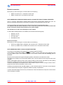
SAFETY STATEMENTS
NOTE
Throughout the manual certain potential problems, or further information
relating to the installation, maintenance, understanding or use of the apparatus
will be highlighted to the operator by indications identified by the adjacent
symbol and text.
CAUTION!
Throughout the manual certain safety or operational related comments and
requirements will be highlighted to the operator by indications identified by the
adjacent symbol and text.
DANGER!
Throughout the manual certain safety or operational related comments and
requirements that could lead to injury or loss of life will be highlighted by the
adjacent symbol and text.
TECHNICAL SUPPORT AND SOFTWARE UPGRADES
Contact your local agent or Tritech International Ltd
Mail
Tritech International Ltd.
Peregrine Road,
Westhill Business Park,
Westhill, Aberdeen,
AB32 6JL, UK
Telephone
++44 (0)1224 744111
Fax
++44 (0)1224 741771
Email
[email protected]
Web
www.tritech.co.uk
An out-of-hours emergency number is available by
calling the above telephone number
If you have cause to use our Technical Support service, please ensure that you have the following
details at hand prior to calling:
•
•
•
•
•
System Serial Number (if applicable)
Serial Numbers of all scanning / profiling heads
Software Revision Number
Fault Description
Any remedial action implemented
The name of the organisation which purchased this system is held on record at Tritech
International Ltd.
Details of new software and hardware packages will be announced at regular intervals.
Depending on the module, free upgrades will be offered in keeping with our policy of
maintaining the highest levels of customer support.
Issue 9
TIL – Eng – Spec – 016
Page 9 of 46
Tritech International Ltd
Micron Sonar OIM
PART 1. SOFTWARE INSTALLATION (WINDOWS 98/2000/XP/VISTA)
PC Hardware Requirements:
Pentium PC
32MB RAM (Windows 98), 128MB (Windows 2000/XP/Vista)
10MB Hard Disk Space (Installation)
Available COM Port (115.2kBaud capable)
16-Bit Colour Graphics Card at 800x600 Resolution
1) Insert the ‘Micron Sonar’ Installation CD into drive and run SETUP.EXE.
2) The Installation will place 2 shortcuts on the Desktop; i) Micron Setup ii) Micron Sonar.
3) The Micron Sonar software is pre-configured to communicate with the Sonar via the COM1 Port @
115,200 Baud, 8 Data, No Parity, 1 Stop.
4) Consult the Micron Sonar software manual for operating instructions and details on how to re-configure
COM Port assignment and telemetry settings.
PART 2. HARDWARE INSTALLATION
Power
The Sonar head should be powered from a clean DC Supply or Battery pack capable of supplying 7 - 50Vdc @
2.2VA. To reduce damage to the sonar head in the event of over voltage it is recommended that an appropriate
fuse is included in the power supply connection.
The Operation LED glows dimly when power is applied (to show it’s alive), then flashes as the head rotates past
centre to show correct operation.
Mounting
The Operation LED should be mounted in the ahead position on the vehicle which is the “zero” position which
relates to “12’o’clock” on the Sonar PPI display. If mounted at a non-zero position then adjust the “Rotation
Offset” control in ‘Sonar Setup’ to re-align the display.
Handling
CAUTION!
CAUTION!
The Micron Sonar head is an oil-filled product and under NO circumstance should it be
opened up or tampered with in any way. There are no user-serviceable parts or internal
switches which would necessitate disassembly.
The ‘Seal Screw’ should never be unscrewed as this may result in oil loss. The
blue/yellow diaphragm on the top of the Sonar head is to allow for volume changes in the
oil at different operating temperatures. This diaphragm should never be poked or
stabbed with sharp instruments.
The depth rating of the Sonar is dependant on the Model of transducer fitted. Please
refer to head label or build sheet for specific unit depth ratings.
CAUTION!
The connector socket is not usable “open face” and should always be sealed with either
a plug or the blanking-plug provided. The ‘AUX’ Port should be blanked off at all times
when not in use.
CAUTION!
- Please also refer to the point listed under the "Further Information" section, when handling or operating.
Issue 9
TIL – Eng – Spec – 016
Page 10 of 46
Tritech International Ltd
Micron Sonar OIM
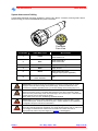
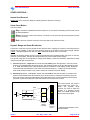
Communication protocol
The Micron sonar is supplied with two communication ports labelled "Main" and "Aux". All communication to the
control PC on the surface should be via the "Main" port, while the "Aux" port is used for daisy chained
communication links to other Tritech sensors such as the RS-485 Micron Echosounder altimeter.
The communication configuration of the "Main" and "Aux" ports can be FACTORY SET. These are Software
selectable comms (RS232, RS485) Notes on changing these are in Appendix A.
The 4 option variants A-D are available
A=Main-485, Aux-485,
B=Main-232, Aux=485,
C=Main-485, Aux-232,
D=Main-232, Aux-232
In this example, the label shows that configuration D has been
selected
The RS232 telemetry is Bi-directional, 3-wire (Tx, Rx and Gnd) between the Sonar head and the PC /
Laptop RS232 COM Port. This may be via an RS232 Modem or Multiplexer.
The RS485 telemetry is Half-duplex, 2-wire (RS485+ & RS485-) between the Sonar head and surface
RS485 connection. Typically, the surface RS485 connection can be an RS485 serial COM Port
installed in the PC or it can be an "RS485 to RS232" signal converter that is attached to the PC /
Laptop's standard RS232 COM Port.
The RS485 circuit inside the head has a factory supplied 150 ohm termination fitted, a
matching 150 ohms may be fitted to the surface if the twisted pair length dictates.
By the above methods, the Sonar Head should be connected through to an available Serial COM Port on the
PC / Laptop installed with the Micron Sonar software.
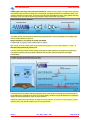
Third Party Communication Devices
RS485 to RS232 converter
If a Micron system is supplied configured RS485 it may be necessary to use an RS232 to RS485 converter to
allow interface with a standard PC com port, as stated above.
The converter must be capable of Half-duplex operation and able to support speeds of at least 115,200
baud.
It is not recommended to use a unit which is powered from the PC com port as this can reduce the
maximum length of twisted pair which the system will operate through.
It is advised that the RS485 circuitry on the converter is optically-isolated to protect both the PC and
the converter from high voltages, which may become present in a fault condition on an ROV umbilical.
NOTES WHEN USING "ADAM 4520" RS232 TO RS485 CONVERTER
Tritech International recommends the use of the above converter. This device can be purchased from Tritech
International Ltd if required. Contact Tritech Technical Support for details.
The Device is externally powered with an input range of 10-30VDC, we recommend the use of 24 volts.
Internal switches are used to set baud rate, their function is detailed on the external case of the unit. It is
imperative that the internal switch is set to match the system baud rate between the head and the PC.
Issue 9
TIL – Eng – Spec – 016
Page 11 of 46
Tritech International Ltd
Micron Sonar OIM
Electrical connection
Whilst wiring up and connecting the converter, adhere to the following;
RS485+ connects to Pin 1 of the Micron Sonar head.
RS485- connects to Pin 2 of the Micron Sonar head.
NOTES WHEN USING "B&B ELECTRONICS 485OT9L OR 485OTLED" RS232 TO RS485 CONVERTER
This is a commonly used RS232 to RS485 interface that provides optical-isolation between the ports. The
Device is externally powered with an input range of 10-30VDC, we recommend the use of 24 volts.
The internal switches and jumpers are used to select the baud rate and communications mode.
It is imperative that the internal switches are set to match the system baud rate between the head and
the PC. Consult the interface documentation on the switch settings.
JP1 should be set to "SD" for the Half-Duplex control method
For half duplex, RS485 operation at 115.2KBaud, we recommend the following setup;
Switches 1 to 4 off,
Switches 5 to 8 on
JP1 set to "SD"
R21 fitted as 4.7KΩ.
Electrical connection
Whilst wiring up and connecting the converter, adhere to the following;
TB1 Pin 2 (Labelled "TDB+") is RS485+ and connects to Pin 1 of the Micron Sonar head.
TB1 Pin 1 (Labelled "TDA-") is RS485- and connects to Pin 2 of the Micron Sonar head.
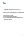
NOTES WHEN USING USB TO RS232 COM PORT ADAPTERS
It is common for new laptops to be supplied without standard COM port hardware.
In this instance a USB to Serial adapter may be used to obtain a “virtual” COM port on such machines. There
are many different types of this adapter available on the market, however note the following prior to
purchase…
Because of the requirement to support half duplex operation, the timeout on the data link is critical.
This means that no delays can be introduced between the PC and the Head, and the strings sent must arrive
complete.
Certain USB adapters buffer the data, which means the Micron Sonar strings get broken up when passing
through such adapters. When this is the case the following symptoms are common…
The Sonar head (Node2) can be detected in the “Micron Setup” program, but when running the “Micron Sonar”
program the Sonar head is intermittent or does not scan.
If problems are experienced with the USB adapters, try first to load the system on a PC with a normal COM port
to confirm that the Sonar head (and, if applicable, RS485 converter) are operational.
A proven USB serial adapter device can be purchased from Tritech International Ltd if required, contact Tritech
Technical Support for details.
Issue 9
TIL – Eng – Spec – 016
Page 12 of 46
Tritech International Ltd
Micron Sonar OIM
System Interconnect Cabling
The Standard Underwater Connector supplied is a Tritech 6-way “Micron” connector, the wiring code is shown
below including pin-outs for RS232/RS485 and power connections.
1
6
2
4
5
3
Connector
Face View
Pin Number
Cable Whip Colour
1
Yellow
RS485 Comms A or
RS232 Comms TX
2
Blue
RS485 Comms B or
RS232 Comms RX
3
Red
Supply Positive Voltage
4
Black
Supply Ground
5
Green
RS232 Comms Ground or
Analogue Output (where applicable)
6
Drain Wire with Black 'Heatshrink' Insulation
CAUTION!
CAUTION!
Wire Function
Earth
Please Note: Connectors should only be applied to the Micron products when the power
supply is turned off. Before turning on the power supply, ensure the EARTH line is not
connected to a positive potential (re Pin 4), as erosion damage to the housing may occur.
Please Note: The Micron series connector is NOT wet-mateable, and although limited
electrical protection circuitry is provided within the Micron units, direct exposure to water,
when the unit is powered may cause erosion damage to the connector pins, or internal fuses
to blow that may only be replaced by the factory.
When either port is not in use, the blanking cap MUST be fitted!
CAUTION!
Please Note: The connector wiring information can be applied to both the "Main" or "Aux"
communication ports. However, the function of pins 1, 2 and 5 depends on the capabilities,
configuration and port of the device connected to.
CAUTION!
Please Note: The sonar head is protected against voltage surges on the power and comms.
lines using internal suppressers. Sustained over voltage will damage the head. To reduce risk
it is strongly recommended that 100mA fuses are used in the comms. lines and an
appropriate fuse used in the power supply (e.g. 1A@12V or 500mA@24V).
Issue 9
TIL – Eng – Spec – 016
Page 13 of 46
Tritech International Ltd
Micron Sonar OIM
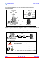
A. RS232 Micron Sonar ("Main" Port):
Communications between the Micron Sonar "Main" port and the PC serial port is 3-wire RS232.
Configuration is as follows;
RS232 Tx (Yel)
1
9-pin Male 'D' COM Port
RS232
Rx
2
RS232
Tx
3
RS232
5 Gnd
Screen 6
2
RS232
Rx (Blu)
RS232 Gnd 5
(Grn)
3
+V
DC (Red)
0v DC
(Blk)
PC / Laptop Computer
(Windows 98 / 2000 / XP)
3-wire RS232
@ up to
115,200 bit/s
4
Connector
Face View
Micron Sonar head
(RS232)
Depending on the type of conductors used, the RS232 may only drive up to 20 metres of copper cabling. For
longer cable lengths it is necessary to run through a repeater or converter, or switch to optical fibre with an
RS232 telemetry option.
A method to operate the (RS232) Micron Sonar head over longer cable lengths would require a pair of RS232
to RS485 converters installed surface and subsea;
3-wire RS232
@ up to
115,200 bit/s
2-wire RS485 /
4-wire RS422
RS232 to
RS485
Converter
RS232 to
RS485
Converter
Micron Sonar head
(RS232)
PC / Laptop Computer
(Windows 98 / 2000 / XP)
CAUTION!
NB: Select converters with an optically-isolated RS485 interface, to
protect the PC serial port.
SUMMARY
• Pin 1 on the Sonar 6-pin "Main" connector port is the RS232 Tx
that should be connected to the RS232 Rx on the PC serial port.
1
6
2
4
5
3
Connector
Face View
Issue 9
•
Pin 2 on the Sonar 6-pin "Main" connector port is the RS232 Rx
that should be connected to the RS232 Tx on the PC serial port.
•
Pin 5 on the Sonar 6-pin "Main" connector port is the RS232
Gnd. This should be connected to the RS232 Common Gnd on
the PC serial port.
TIL – Eng – Spec – 016
Page 14 of 46
Tritech International Ltd
Micron Sonar OIM
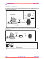
B. RS485 Micron Sonar ("Main" Port):
For the RS485 telemetry option, this can run directly over a twisted pair cable of typical length up to as much as
2km. The first option would be to run the telemetry straight into the PC but for this an RS485 Serial Comms card
would need to be fitted inside the PC;
RS485-A (Yel)
1
Screen
PC / Laptop Computer
(Windows 98 / 2000 / XP)
2 RS485-B
(Blu)
6
3 +V DC
(Red)
N/C 5
(Grn)
0v DC
(Blk)
4
Connector
Face View
2-wire RS485
@ up to
115,200 bit/s
Micron Sonar head
(RS485)
RS485 COM Port
Alternatively, the RS485 Micron Sonar can be connected to the PC RS232 Port via an RS485 to RS232
external converter;
3-wire RS232
@ up to
115,200 bit/s
2-wire RS485
RS232 to
RS485
Converter
Micron Sonar head
(RS485)
PC / Laptop Computer
(Windows 98 / 2000 / XP)
1
6
2
4
5
3
Connector
Face View
Issue 9
SUMMARY
• Pin 1 on the Sonar 6-pin "Main" connector port is the RS485 + that
should be connected to the RS485 + on the PC RS485 serial port
or signal converter box.
•
Pin 2 on the Sonar 6-pin "Main" connector port is the RS485 - that
should be connected to the RS485 - on the PC RS485 serial port or
signal converter box.
TIL – Eng – Spec – 016
Page 15 of 46
Tritech International Ltd
Micron Sonar OIM
Further Information
General
• The Micron Sonar head is an oil-filled product and under NO circumstance should it be opened up or
tampered with in any way. There are no user-serviceable parts or internal switches which would
necessitate disassembly.
•
The ‘Seal Screw’ should never be unscrewed as this may result in oil loss. The blue/yellow diaphragm
on the top of the Sonar head is to allow for volume changes in the oil at different operating
temperatures. This diaphragm should never be poked or stabbed with sharp instruments.
•
The Maximum depth to which the Sonar can be lowered is given on the Sonar configuration label and in
the Build documentation.
Connector
• The connector socket is not usable “open face” and should always be sealed with either a plug or the
blanking-plug provided.
•
The ‘AUX’ Port should be blanked off at all times when not in use.
•
Care should be taken when mating the connector, with either a plug or a blanking-plug, to ensure both
mating ends are clean and dry.
•
Special attention should be given to checking the O-ring for dirt. The O-ring is located under the lockring on both the plug and the blanking plug.
•
When mating the connector, first locate the plug on its ‘D’ profile, push together as far as possible and
then tighten the lock-ring. The action of tightening the lock-ring draws the two mating ends fully
together.
•
The connector lock-ring needs only to be finger tight. The use of any tools to tighten the lock-ring further
is not necessary and could result in damage to the connector.
Telemetry
•
The Micron Sonar head should be programmed to communicate at a default Baud Rate of 115,200 @ 8
Data, No Parity, 1 Stop. This can be re-configured through the Setup program (consult Software
Manual).
•
It is recommended that a Baud Rate of 57,600 or above be maintained wherever possible to provide
enough system bandwidth to operate the Sonar at its maximum resolution.
•
For the RS232 telemetry option, if a direct RS232 cable is to be used then this will have a limit of
typically 10 to 15 metres in length. Otherwise, a modem with fibre optic interface should be used to
increase telemetry distances.
•
To prevent damage to the PC / Laptop it is best to use an RS232 / RS485 Serial Port (or Signal
Converter) that has optically isolated inputs for protection.
•
The ‘Aux’ Port will be factory configured to RS-485, ready for attachment of the RS-485 Micron
Echosounder. It may be possible to connect other serial devices to the ‘Aux’ port – contact Tritech
Technical Support for further information.
Issue 9
TIL – Eng – Spec – 016
Page 16 of 46
Tritech International Ltd
Micron Sonar OIM
Delrin Housed DST Micron: Mechanical Mounting
Four brass M3x0.5mm tapped inserts are provided on the bottom of the Micron Sonar to ease mounting on flat
surfaces, alternately the Micron may be gently gripped by a 50mm diameter clamping mechanism around the
bottom part of its housing.
Aluminium Housed DST Micron: Mechanical Mounting
Four tapped holes in the aluminium body are provided on the bottom of the Micron Sonar to permit mounting on
flat surfaces, or alternately the Sonar may be gently gripped by a 50mm diameter clamping mechanism around
the bottom part of the housing.
Please Note: It is recommended that any fixing screws used should be of a non-metallic
material to reduce the risk of corrosion around the fixing positions.
CAUTION!
24.00
24.00
THREAD M3x0.5
DEPTH 4.50
All dimensions are in
millimetres.
50.00 Dia
Specification
Operating Frequency
Beamwidth, vertical
Beamwidth, horizontal
Range Settings
Scan Sectors
Step Speed
True Acoustic Zoom
Instant Reversal
Image Measurement
Inverted Head Operation
Power Requirements
Data Communication
Communication Requirements
Topside Control
Chirp: Centre frequency of 700 KHz
30°
3°
From 2m (6.5ft) to 100m (328ft)
User selectable up to 360° continuous
Normal, Fast or Very Fast
Yes
Yes
Yes
Yes
7V - 50V @ 2.2VA DC
RS485 (twisted pair), RS232 (via modem up to 115Kbps)
Maximum cable length 1000 meters (using RS485)
Customer supplied PC or Laptop using standard serial comms
port.
Windows 98, 2000, XP or Vista operating system.
Software
Maximum diameter
Maximum height
Weight in air
Tritech Seanet(OEM) display
56mm (2.20 inches)
78.5mm (3.09 inches)
Delrin Housed DST Micron
290g (10.25 ounces)
Aluminium Housed DST Micron
330g (11.6 ounces)
Delrin Housed DST Micron
145g (5.12 ounces)
Aluminium housed DST Micron
185g (6.6 ounces)
Units fitted with Air backed Transducers
500m (1640ft)
Units fitted with SADM backed Transducers
750m (2460ft)
Optional 3000m (9842ft) version available
-10°C to +35°C
-20°C to +50°C
Weight in water
Operational Depth
Operating Temperature
Storage Temperature
Issue 9
TIL – Eng – Spec – 016
Page 17 of 46
Tritech International Ltd
Micron Sonar OIM
PART 3. OPERATION OF THE MICRON SONAR APPLICATION
The Micron Sonar application can be run from the ‘Programs’ group in the Windows ‘Start’ menu or from the
desktop by double clicking on the shortcut icon as shown below…
The Micron Sonar screen display is a Single Sonar application as shown below…
Sonar
Status
Area
Sonar PPI
Display
Dynamic
Range &
Sonar Rx
Indicator
Speed /
Resolution
Zoom
On/Off
Date /
Time
Sonar Pause
button
Sonar
Gain
Range
Scale
Scan
Sector
Transmit
Frequency
Setup Menu
Issue 9
TIL – Eng – Spec – 016
Page 18 of 46
Tritech International Ltd
Micron Sonar OIM
MAIN FUNCTION BUTTONS
There are 7 buttons / controls on the bottom of the screen display that are used to configure the Sonar and to
setup the screen layout;
‘Setup Menu’ button
When this button is clicked a Popup menu will appear where the Sonar and display settings can be
configured via a number of menu items. These will be explained later.
‘Sonar Gain’ button
This sets the sonar receive gain (0 – 100%) as required – typically this is around 20% but is varied according
to water and target conditions and user preference.
‘Range Scale’ button
This sets the maximum range (2m – 100m) the sonar will scan. Long ranges are scanned more slowly than
short ranges due to the limit imposed by the velocity of sound in water.
‘Scan Sector’ button
This sets the width of the scanned sector. Typically this will be adjusted according to the required seabed
coverage. There are several sector settings including 360°, 180°, 135°, 90° and 45°.
‘Speed / Resolution’ button
This button will toggle through 3 preset settings which will vary the Sonar scan speed and image detail. Use
the ‘Normal’ settings in most cases which will produce the best resolution. However, toggle to ‘Fast’ or ‘Very
Fast’ settings if a higher scan speed is required. In normal operations, select ‘Normal’ for detailed
examination of static targets where a slower scan update will not pose a problem. Select ‘Fast’ if a fast scan
update is required at the cost of a little image detail. The ‘Very Fast’ setting will produce the lowest resolution
and image quality but will produce the fastest scanning.
‘Zoom On/Off’ button
Toggles a zoom box on the display which can then be positioned by the cursor. This is a true acoustic zoom
magnifier that will give more image detail in the area surrounded by the zoom box. The Zoom window size
and magnification can be adjusted in the ‘Setup Menu’.
‘Transmit Frequency’ button
This is set at the chirp Sonar transmit pulse frequency of 750 KHz.
‘Dynamic Range’ / Contrast slider
This is on the left hand side of the Sonar display and sets the contrast between hard and soft targets.
Usually set to user preference, it can help find small features in generally featureless situation or exclude
clutter from a heavily featured seabed. More details concerning the usage of this control can be found in
later pages of this manual.
Issue 9
TIL – Eng – Spec – 016
Page 19 of 46
Tritech International Ltd
Micron Sonar OIM
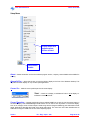
Setup Menu
Popup menu that
appears when
button clicked
Setup Menu
button
About – States information such as the software program version, company contact details and available PC
memory.
AlwaysOnTop – Select this function to bring the Micron display to the front of the Windows desktop. This
will place the Sonar display On Top of other open applications.
Cursor On – Adds the cursor position panel to the sonar display.
'Polar' – Check on to display co-ordinates in Polar or off to display coordinates in Cartesian format.
Cursor Reporting – Outputs a serial string from a selected COM Port on each click of the mouse button on
the Sonar display. The Left/Middle/Right Mouse button can be used to click anywhere on the Sonar display,
such as on a target, which will then output a serial string with the Range and Bearing point information of that
target. Appendix C describes the format of the serial output string. The ‘Com Port’ menu item describes how to
enable and configure a COM Port for the Cursor Reporting output.
Issue 9
TIL – Eng – Spec – 016
Page 20 of 46
Tritech International Ltd
Micron Sonar OIM
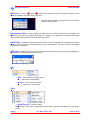
Markers On – Adds A (
) and B ( ) markers under left button control. The range and bearing to each
marker & separation and relative bearing are shown.
Select A or B on the Marker panel and then click on the main
display to position marker.
Echosounder Chart – Used to display the altitude data from a Micron Echosounder connected to the
Micron Sonar Aux port. This graphical chart display is in addition to the Altitude Text box display. More details
on the Echosounder interface can be found later in this manual.
Video Panel – Enables the Video Input preview window. If the PC is installed with a video capture card then
the input from its source (i.e. composite camera input) can be displayed in the preview window. More details
can be found in Appendix D.
GPS Input – Enables the ‘GPS’ Popup form to display position data from a GPS input string. More details on
the GPS interface can be found later in this manual.
Log…
… Play – Use to play back recorded log data.
Follow the on screen display.
… Record – Use to record Sonar data.
Follow the on screen display.
Print…
… Quick Print On – This has 2 effects;
When printing ‘To File’ then a bitmap will be saved to the Log directory with bitmap name having time
format.
Issue 9
TIL – Eng – Spec – 016
Page 21 of 46
Tritech International Ltd
Micron Sonar OIM
When printing ‘To Printer’ then Print Setup dialog box will not appear and default printer and it’s settings
are chosen.
… Setup Printer – Select and setup the Windows Printer.
… To File – Print screen to a bitmap file. When ‘Quick Print On’ = Off, a dialog box will appear
allowing the user to select file path (Log directory) and bitmap name.
… To Printer – Print to Windows Printer. When ‘Quick Print On’ = Off, a setup dialog will appear
allowing the user to select printer and set it’s options before printing.
Title Bar – This is used to edit the text that is displayed on the title bar (top) of the Sonar display.
Colours – Use to select from several preset colour schemes for the Sonar display.
Language – Select from several international languages. Currently only UK and US
English are available.
Units – Select the units for the Sonar Range labelling and cursor co-ordinates. Metres
and Feet are the available options.
Zoom Setup – Sets the size and magnification factor of zoom box.
The Size shows the normal display screen zoomed area as a percentage
of the zoom display window.
The Factor shows the number of zoomed range bins for each normal
range bin.
Issue 9
TIL – Eng – Spec – 016
Page 22 of 46
Tritech International Ltd
Micron Sonar OIM
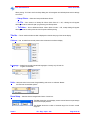
Sonar Setup – Sets various head options.
‘VOS’ – used to enter a Velocity Of Sound value that will be
applied in the Sonar display.
‘Inverted Head’ - swaps the display from left to right. Enable if
mounted boot up.
‘Scan Sector’ – Use this control to select the scanning sector
when the display is in a 180 degree sector view. There are 4 sectors
indicated by the arrow position; Up = forward, Right = Starboard, Left =
Port, Down = Aft.
‘Rotation’ – This is a display correction. In cases where the Sonar is not mounted with the Sonar
‘Operation LED’ in the ahead or “zero” position, the Rotation offset can be adjusted to correct for
misalignments or for circumstances where the Sonar has to be mounted at a non-zero position. For
instance, if the Micron is mounted with Operation LED at 90 degrees either side of the ahead position then
enter a +/-90 degree offset to correct the display plotting.
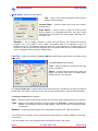
Com Port – Select and configure the ‘Sonar COM Port’ that the Micron Sonar will be connected to on the
PC or Laptop.
The Sonar Com Port has 2 settings…
‘Port’ – Select the COM Port number that the Sonar
head is connected to.
‘Baud’ – Set the COM Port baud rate to match the
setting of the Micron Sonar head. The default factory
setting for Sonar is 115,200 baud.
The ‘Auxiliary Output Port’ is the port that is used to send Sonar Aux Port* data such as that from the Micron
EchoSounder. The ‘Auxiliary Output Port’ is also used to send Cursor Reporting** strings as described earlier.
The Auxiliary Output Port has 3 settings…
‘Port’ – Select the COM Port number that the Sonar Aux Port and/or Cursor Reporting data is to be output on.
‘Type’ – Sets the Type of data to be output on the port. Options are; ‘Sonar Aux’ = Sonar Aux Port data only,
‘Cursor’ = Cursor Reporting data only, ‘Aux + Cursor’ = Sonar Aux Port and Cursor Reporting data
out same port.
‘Enabled’ – Enables the Auxiliary Output Port to output data as selected in the ‘Type’ drop-down list.
* For full Sonar Aux Port details, see the ‘Outputting Echosounder Data from a Surface COM Port’ section later
in this manual.
** For more details on the Cursor Reporting output, see Appendix C later in this manual.
Issue 9
TIL – Eng – Spec – 016
Page 23 of 46
Tritech International Ltd
Micron Sonar OIM
OTHER CONTROLS :Instant Scan Reversal
Double-click on the Sonar PPI display to instantly switch the direction of scanning
Sonar Pause Button
This has 3-states;
Grey: The button is disabled whenever the Sonar is not connected or telemetry with the Sonar has not
yet been established.
Green: The Sonar is active and scanning. The button is now active and can be de-pressed to pause
the Sonar scanning.
Red: The Sonar is paused. Clicking on the Pause button will re-start the Sonar.
Dynamic Range and Sonar Rx Indicator
The dynamic range bar is the A/D sample window (with 64-colour mapping) for the Sonar receive signal (which
extends from 0 to 80dB). To the right of the dynamic range bar is the Sonar receive signal strength indicator
(Yellow = Average amplitude over scan-line, Red = Maximum amplitude echo for scan-line).
Normally the sampling window should not need to be adjusted from its default position (as shown on the left).
However, if used properly, adjusting the sample window can produce better quality imaging.
The dynamic range bar can be adjusted to change Sonar display contrast and sensitivity. Adjustment is made
using the left and right mouse buttons.
1) Contrast adjustment – Right-click on the bar and whilst holding down the right button, move the mouse
up/down to increase/decrease the size of the bar. The sampling window can be any size between a range
of 9 - 25dB. Decrease the size of the sampling window to increase the sonar display contrast. Ideally the
control should be set somewhere in the centre of the allowed range (16 - 18 dB) to give the best results
under most conditions. Select a high value to reduce the contrast of the sonar display.
2) Sensitivity adjustment – Left-click on the bar and whilst holding down the left button, move the mouse
up/down to decrease/increase the Sensitivity of the Sonar receiver. Increasing the Sensitivity (move bar
down) will produce a more saturated display with greater weak-return content. Decreasing the Sensitivity
(move bar up) will omit background noise and low level returns seen at the receiver
The sonar receiver will accept a
return signal in the region of 0 80dB.
The
dynamic
range
controls are used to adjust the
position of a sampling window
within the 0-80dB dynamic range
band of the receive signal.
80dB
26
0dB
RECEIVE SIGNAL
DYNAMIC
RANGE
CONTROL
SCREEN
COLOUR
SCALE
- Idealised representation of A/D
Sample window
Issue 9
TIL – Eng – Spec – 016
Page 24 of 46
Tritech International Ltd
Micron Sonar OIM
CHIRP TECHNOLOGY
CHIRP is an acronym for Compressed High Intensity Radar Pulse.
CHIRP techniques have been used for a number of years above the water in many commercial and military
RADAR systems. The techniques used to create an electromagnetic CHIRP pulse have now been modified and
adapted to commercial acoustic imaging sonar systems. Tritech International Limited has now introduced
CHIRP as its core acoustic engine for all its new range of Digital Sonar Technology (DST) sonars.
To understand the benefits of using CHIRP acoustic techniques, we need to analyse the limitations using
conventional monotonic techniques. An acoustic pulse consists of an on/off switch modulating the amplitude of
a single carrier frequency.
The ability of the acoustic system to resolve targets is determined by the pulse length; this, however, has its
drawbacks. To get enough acoustic energy into the water for good target identification and over a wide variety
of ranges, the transmission pulse length has to be relatively long. The equation for determining the range
resolution of a conventional monotonic acoustic system is given by:
Range resolution = (pulse length x velocity of sound) / 2
In a conventional Tritech system the smallest pulse length is 50 micro seconds and velocity of sound in water
(VOS) 1500 metres/second (typical). Therefore our range resolution = 37.5mm. This result effectively
determines the range resolution (or ability to resolve separate targets) of our monotonic acoustic imaging
system.
Using the example above, if two targets are less than 37.5mm apart then they cannot be distinguished from
each other. The net effect is that the system will display a single large target, rather than multiple smaller
targets.
Issue 9
TIL – Eng – Spec – 016
Page 25 of 46
Tritech International Ltd
Micron Sonar OIM
CHIRP signal processing overcomes these limitations. Instead of using a burst of a single carrier frequency,
the frequency within the burst is swept over a broad range throughout the duration of transmission pulse. This
creates a 'signature' acoustic pulse - the sonar knows what was transmitted and when. Using 'pattern-matching'
techniques, it can now look for its own unique signature being echoed back from targets.
In a CHIRP system, the critical factor determining range resolution is now the bandwidth of the CHIRP pulse.
Now the range resolution is given by:
Range resolution = (2 x velocity of sound) / bandwidth
The bandwidth of a typical Tritech CHIRP system is 100kHz.
With velocity of sound in water (VOS) 1500 metres/second (typical), our new range resolution = 7.5mm... a
theoretical improvement by a factor of 5!
This time, when two acoustic echoes overlap, the signature CHIRP pulses do not merge into a single return.
The frequency at each point of the pulse is different, and the sonar is able to resolve the two targets
independently.
The response from the 'pattern-matching' algorithms in the sonar results in the length of the acoustic pulse no
longer affecting the amplitude of the echo on the sonar display. Therefore, longer transmissions (and operating
ranges) can be achieved without a loss in range resolution.
Additionally CHIRP offer improvements in background noise rejection, as the sonar is only looking for a swept
frequency echo, and removes random noise or out-of-band noise.
Issue 9
TIL – Eng – Spec – 016
Page 26 of 46
Tritech International Ltd
Micron Sonar OIM
Sonar Status
Various error codes are reported in the Sonar Status Area. These help the user determine any faults with
equipment or cabling, as a guide to making any corrections or replacements.
Sonar Status
Status Codes are as follows…
'Centre'
:
‘Timeout’
:
There is no communication with the Sonar head. Check the
cable wiring is okay, the Sonar is powered and the correct COM Port and baud
rate are configured in the Tools Menu.
'Log xxx k'
:
This is displayed when the log record facility is ON and
shows the current size of log file.
‘Play xxx’
:
This is displayed when the log play facility is ON and shows
the current record number within the log file for reference.
The transducer is not passing through the Ahead position at
the correct sequence point. Physical damage internal to the
Boot is the most likely cause of this.
MAINTENANCE
Head Maintenance
Wash down with fresh water each time a unit is recovered from the water, paying particular attention to the boot
and connector areas.
Although units are designed for a wide temperature range it is best to avoid temperature extremes for long
periods and protect units from bright sunlight.
Repairs are by major unit change out which may involve reprogramming a head. In these cases instructions will
be supplied.
It is recommended that usage logs are maintained and that the heads are returned to vendor at 4000-hour
intervals for routine inspection/replacement of slip rings, compensation oil and O-ring seals
Underwater cables are not normally within the scope of supply, but will also require regular inspection.
CAUTION!
The Micron Sonar head is an oil-filled product and under NO circumstance should it be
opened up or tampered with in any way. There are no user-serviceable parts or internal
switches which would necessitate disassembly.
Cables
The cables are high quality with low halogen jackets, which should provide long service life without problems.
Care should be taken to ensure that they are properly sited during installation to avoid movement and fatigue,
but
otherwise
no
maintenance
is
required.
Issue 9
TIL – Eng – Spec – 016
Page 27 of 46
Tritech International Ltd
Micron Sonar OIM
Computer
The PC / Laptop computer should be loaded with a standard version of Windows 98 / 2000 / XP or Vista. If for
any reason it is necessary to reload the Sonar system this should be done using the CD supplied. Follow the
setup dialog during installation.
The Sonar software can be reloaded as follows…
1) Insert the Sonar CD into the CD ROM drive.
2) Browse the CD ROM drive and run Setup.exe from the root. Follow the on screen directions. This will
automatically install the Sonar software to the Program Files directory on the C:\ drive.
3) The Registry retains any user-configured changes. When Setup.exe is run the registry will be set back to a
factory default setting.
4) Shortcut(s) will automatically be created on the Windows Desktop to run the Sonar software and any utility
programs that may have been supplied.
To Remove the Sonar software, use “Settings\ControlPanel” from the Windows Start Menu…
1) Run Add/Remove Programs and select SeaNet.
2) Follow the on screen directions and choose Uninstall from the options.
3) On completion all the above installation will be removed, including the Registry settings and Desktop
Shortcuts
4) The Screen resolution should be set to maximum 1024x768 at either 16-bit or 32-bit colours. A resolution of
800 x 600 is optimal for display purposes.
Issue 9
TIL – Eng – Spec – 016
Page 28 of 46
Tritech International Ltd
APPENDIX A:
Micron Sonar OIM
MICRON SETUP PROGRAM
Important: The Setup program forms part of the Seanet software suite, which includes control and display of
other, multiple devices such as Sidescan, Profiler and Bathy. This Setup utility therefore includes options such
as Sound, GPS, TCM-2 that are only available with other displays in the Seanet suite and not intended for
Micron OEM software which is a Sonar only program.
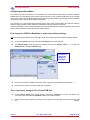
CHANGING MICRON SONAR BAUD RATE
The system has been factory set and should not need to be altered in most circumstances. However, there may
be times when the Baud rate may need to be changed to satisfy field requirements. These changes can be
made from the Seanet Setup / Micron Setup Program;
There are only 2 areas within the Setup program that will need to be entered for Micron Sonar operation…
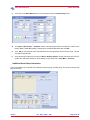
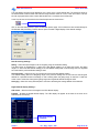
1. The ‘Utilities’ – ‘Com Setup’ menu item (shown above) is used to change the Settings of the Surface
computer COM Port. This needs to be configured correctly to initially communicate with the Micron
Sonar so that new Baud Rate settings can then be downloaded to the Sonar head.
2. Clicking on ‘Setup’ – ‘Aif Card’ will open the ‘Aif Setup’ pop-up panel with settings for the Aif (Acoustic
interface) card. In the case of the Micron system, the Acoustic interface is via a COM port. Always
ensure that the ‘Enabled’ check-box is checked / ticked to enable the COM port. This is only applicable
for communicating with the Micron Sonar through the Setup program and does not affect the main
Micron display program.
Issue 9
TIL – Eng – Spec – 016
Page 29 of 46
Tritech International Ltd
Micron Sonar OIM
Configuring New Baud Rates
This should only ever be necessary to communicate over a longer RS232 serial cable (>10metres), installed
between the PC and the Micron Sonar head (or signal converter) or over a modem system that can only handle
lower rates. In this event, the Baud Rate should be kept as high as possible to give enough system bandwidth
for the Sonar head to operate at full speed and resolution.
The first step is to communicate with the Micron Sonar head, which involves setting the COM Port settings
within the Setup program to match the Micron head’s Baud rate and COM port connection.
It may be necessary to use a short serial cable to first communicate with and re-program the Micron Sonar head
before it is then installed on the longer cable or modem system.
First change the COM Port Baud Rate to match current Sonar settings…
N.B. The Setup program default will be COM1 @ 115.2K which matches the Micron display software defaults.
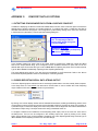
a)
Click on the Utilities menu item and select Com Setup from the drop-down list.
b)
The Channel Setup panel will appear as follows. Click on the ‘Settings’ ellipsis (‘…’) to open the
AifSetupForm to change the Baud setting.
Click here to
change the
Serial Port
Baud Rate.
c)
Ensure that ‘V3 Mode’ is disabled,‘Use Event Char’ is greyed out and disabled and ‘Rx Sleep’ = 1.
d)
Close the Form via the ‘X’ button for settings to be applied.
Then, if necessary, change the PC’s Serial COM Port
e)
In the Channel Setup panel (shown above), change the ‘COM Port’ to match the Micron port
connection. Also ensure that the ‘Enabled’ check-box is checked / ticked.
f)
Close down the Channel Setup by clicking on the ‘X’ button on the top-right. New settings will be saved
and
applied.
Issue 9
TIL – Eng – Spec – 016
Page 30 of 46
Tritech International Ltd
Micron Sonar OIM
To Program the new Serial Baud Rate into Sonar…
a)
First ensure that the Micron Sonar head (Node 2) is detected and displayed in the Setup program
table…
b)
Click on the Action column for Node 2 and then select Setup, as shown…
NB: The settings for the Chirp Sonar are factory set and cannot be changed by the user. The Comms
Mode is also factory set and should not be changed.
Issue 9
TIL – Eng – Spec – 016
Page 31 of 46
Tritech International Ltd
Micron Sonar OIM
c)
Then Click on the Baud Rates button in the next panel to open the Comms Setup panel…
d)
The Async 0 (Serial LAN) -> Hi-Speed column is the setting that needs to be altered. It will be at the
factory default 115200 Baud setting. Change this to the desired Baud Rate then click OK.
e)
Then, OK the next panel and the new Baud Rate will be programmed into the Micron Sonar. This will
only take several seconds.
f)
Close the Setup Program and re-open the Micron display software. Change the Baud rate of the PC
COM Port to match the new Micron sonar settings. This is performed in Tools Menu – Com Port.
Additional Sonar Setup information.
This screen displays the computed ADC calibration value along with a quality factor. This is factory set and this
page is read only.
Issue 9
TIL – Eng – Spec – 016
Page 32 of 46
Tritech International Ltd
Micron Sonar OIM
To Program new comms configuration into Sonar…
CAUTION!
NB: Before proceeding with the Comms configuration process, please make sure that
you have the hardware to configure the system to the desired Comms protocol. As once
the head has been programmed the head can not be recovered without it.
a)
First ensure that the Micron Sonar head (Node 2) is detected and displayed in the Setup program table.
If not please reference the Sonar Manual Appendix A for Help.
b)
Click on the Action column for Node 2 and then select Setup, as shown…
c)
The Comms Mode column is then used to alter the Main and Aux comms. These will initially be at the
factory setting. These comms modes should only be set to either RS232 or RS485. Change these to the
desired Comms Modes.
Issue 9
TIL – Eng – Spec – 016
Page 33 of 46
Tritech International Ltd
Micron Sonar OIM
d)
Then click OK and the new Comms Mode will be programmed into the Micron Sonar. This will only take
several seconds.
e)
Close the Setup Program and re-open the Micron display software. Change the Hardware comms
configuration between the Micron and the topside to match the Comms protocol of the sonar. The Micron
Sonar head (Node 2) should be detected and displayed in the Setup program table. If not please
reference the Sonar Manual Appendix A for Help.
Note: The assigned Com Port on the PC may now be different to the original set up. This can be checked via
the
Windows
Control
Panel
and
System
Hardware
Configuration.
Issue 9
TIL – Eng – Spec – 016
Page 34 of 46
Tritech International Ltd
APPENDIX B:
‘AUX’ PORT
Micron Sonar OIM
CONNECTING RS-485 MICRON ECHOSOUNDER TO
Note: The Micron ‘Aux’ port will be factory configured to RS-485 at a Baud Rate of 115.2kBaud. This is the
mode that is required to connect the RS-485 Micron Echosounder.
INTRODUCTION
The Auxiliary port on the Micron can be used to connect an RS-485 Micron Echosounder for purpose to provide
Altitude data on the surface Sonar display. This altitude data will be logged alongside Sonar data and so be
displayed during log file playback.
The Micron Echosounder benefits from Tritech’s unique Digital Sonar Technology (DST) using CHIRP signature
pulses to allow accurate height above seabed measurements through reduced range resolutions (+/- 1mm).
MICRON ECHOSOUNDER POWER REQUIREMENTS
The RS-485 Micron Echosounder has the same input supply voltage range as the Micron Sonar head which is
12-50V. The Micron Echosounder can be powered from the ‘Aux’ port of the Micron Sonar. This supply will be
drawn directly from the input supply to the Micron ‘Main’ Port.
CONNECTOR WIRING DETAILS
The Micron Echosounder connector is a Tritech 6-way “Micron” connector, the same type that is fitted to the
Micron Sonar head. The connector wiring details for the RS-485 Comms are as follows;
1
6
2
4
5
3
Connector
Face View
Issue 9
Pin Number
Cable Whip Colour
Wire Function
1
Yellow
RS485 Comms A
2
Blue
RS485 Comms B
3
Red
Supply Positive Voltage
4
Black
Supply Ground/RS232 Ground
5
Green
Supply Ground/RS232 Ground
6
Drain Wire with Black 'Heatshrink' Insulation
Earth
TIL – Eng – Spec – 016
Page 35 of 46
Tritech International Ltd
Micron Sonar OIM
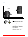
INTERCONNECT CABLE DETAILS
For the connection of the Micron Echosounder to the Micron ‘Aux’ Port a double-ended 6-way Micron
interconnect cable is required. This needs to be a “one-to-one” wired cable.
12-50VDC @ 6VA
(2.5VA Sonar +
3.5VA
EchoSounder)
RS-232/RS-485
Serial Comms to
Surface
MAIN
AUX
RS-485
Comms
+ Power
MAIN
SUMMARY
1
6
2
4
5
3
Connector
Face View
Issue 9
•
Pin 1 on the Micron Sonar 6-pin ‘Aux’ connector port is
the RS485 + that should be connected to the RS485 +
(Pin 1) on the Micron Echosounder ‘Main’ Port.
•
Pin 2 on the Micron Sonar 6-pin ‘Aux’ connector port is
the RS485 - that should be connected to the RS485 –
(Pin 2) on the Micron Echosounder ‘Main’ Port.
•
Pin 3 on the Micron Sonar 6-pin ‘Aux’ connector port is
the DC Power Supply that should be connected to DC
Input (Pin 3) on the Micron Echosounder ‘Main’ Port.
•
Pin 4 on the Micron Sonar 6-pin ‘Aux’ connector port is
the DC Supply Ground that should be connected to DC
Ground (Pin 4) on the Micron Echosounder ‘Main’ Port.
•
Pin 5 on the Micron Sonar can be left disconnected –
On the Micron this is the RS-232 Ground line which is
internally shorted to Pin 4.
•
Pin 6 on the Micron Sonar 6-pin ‘Aux’ connector port is
the Earth that can be connected through to the Earth
(Pin 6) on the Micron Echosounder ‘Main’ Port.
TIL – Eng – Spec – 016
Page 36 of 46
Tritech International Ltd
Micron Sonar OIM
MICRON ECHOSOUNDER OPERATING MODES
When connected to the Micron Sonar ‘Aux’ Port, the Micron Echosounder should be configured in a FreeRunning Output mode.
CAUTION!
Note: When supplied for Micron Sonar Aux Port use, the Micron EchoSounder will be
factory preset for this mode of operation. This is a free-running mode that is set to RS485, Zero No Echo, 3P3 at 115200Baud (8 Data, No Parity, 1 Stop bit). This mode
cannot be changed in the field. Contact Tritech for more details.
There are various data string output modes that can be configured in the Micron Echosounder which are all
compatible with the Micron Sonar ‘Aux’ port connection. These include:
1. 3P2 = “xxx.xxm<cr><lf>”
where;
“xxx.xx” is range in metres to 2 decimal places,
“m” is units label for metres,
<cr><lf> is Carriage Return and Line Feed terminators.
2. 3P3 = “xxx.xxxm<cr><lf>” (factory preset mode)
where;
“xxx.xxx” is range in metres to 3 decimal places,
“m” is units label for metres,
<cr><lf> is Carriage Return and Line Feed terminators.
3. Serial NMEA $DBT message = “$PADBT,xxx.xx,f,yyy.yy,M,zzz.zz,F*hh<cr><lf>”
where;
“xxx.xx” is range in feet,
“yyy.yy” is range in metres,
“zzz.zz” is range in fathoms,
“hh is an 8-bit checksum computed by Exclusive-OR’ing of the character,
<cr><lf> is Carriage Return and Line Feed terminators.
The default Baud Rate of the Micron Echosounder output is 115kBaud (8 data, 1 stop, no parity).
NOTE: No analogue output is available from the Echosounder when connected to the Micron Sonar
auxiliary port.
Issue 9
TIL – Eng – Spec – 016
Page 37 of 46
Tritech International Ltd
Micron Sonar OIM
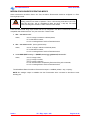
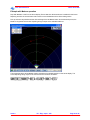
SURFACE ALTITUDE DISPLAY
The free-running Altitude data output from the Micron Echosounder, as received at the Micron Sonar ‘Aux’ port,
will be forwarded to the surface (between Sonar data packets). At the surface, the Micron Echosounder Altitude
data will be displayed on the settings bar at the bottom of the Sonar display window.
Text Box display of freerunning Altitude data
output from Micron
Echosounder.
The Altitude display box will auto-appear on detection of the Altitude data.
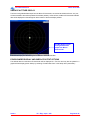
ECHOSOUNDER DISPLAY AND SURFACE OUTPUT OPTIONS
The altitude data from the Micron Echosounder will be displayed in a Text box and may also be plotted in a
graphical Chart display (shown below) by selecting ‘EchoSounder Chart’ in the Setup menu (see earlier)…
Issue 9
TIL – Eng – Spec – 016
Page 38 of 46
Tritech International Ltd
Micron Sonar OIM
Chart can be
dragged and
docked to other
areas of the
screen by picking
up the control
bar.
Scrolling altitude
Chart. Displays
current altitude
(solid blue) and
average altitude
(red line).
Issue 9
TIL – Eng – Spec – 016
Page 39 of 46
Tritech International Ltd
Micron Sonar OIM
The chart display will auto-range depending on the value of the current altitude data. The maximum range for
the Echosounder is 50m and the chart will auto-range between values of 0-10m, 0-30m and 0-50m. The Text
box will only appear when there is active altitude data from a connected Aux Echosounder.
In the Top-Left corner of the Chart is the Chart Setup button as shown below…
Chart Setup button.
Click on the Chart Setup button to open the Altimeter Options page. This is where there are several settings for
the Altimeter data processing. There is also an option to enable a digital display of the Altitude readings.
Data Processing Settings…
Gating – Select what percentage to use for the gating range of an altitude reading.
The gating range is calculated as +/- gating of the last altitude reading (i.e. for gating set at 20%, the gating
range is +/- 20% of the last altitude reading). If the next altitude reading falls out of this range then it is regarded
as invalid and the previous altitude reading is used.
Hold Last Value – Select how long you should hold onto the last valid altitude reading.
If an altitude reading falls out of the gating range of the previous reading then we can hold onto the last good
altitude for a specified number of readings or until a reading within the gating range is received. If ‘Hold Last
Value’ is set to 0 then the Chart ignores gating ranges and regards all altitude readings as valid.
Averaging – Select how many data samples to use when calculating the average altitude of the altimeter.
Digital Altitude Display Settings…
LED Colour – Sets the colour of the digits in the LED Altitude display.
Enabled – Enables the Digital Altitude display. The LED display will appear at the base of the chart when
enabled (as shown below).
LED digital display
of Altitude.
Issue 9
TIL – Eng – Spec – 016
Page 40 of 46
Tritech International Ltd
APPENDIX C:
Micron Sonar OIM
COM PORT DATA I/O OPTIONS
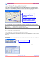
1. OUTPUTTING ECHOSOUNDER DATA FROM A SURFACE COM PORT
In addition to displaying the Micron Echosounder altitude data on-screen, there is also the option to forward the
altitude string to another computer via a surface serial link. To configure this option, a COM Port must first be
allocated and enabled for this purpose. This configuration is performed by clicking on the ‘Com Port’ menu item
in the Setup menu (see earlier). This will open the following dialog box…
Configure the ‘Auxiliary Output
Port’ for outputting the Micron
Echosounder altitude string from
a surface COM Port.
Set Type to ‘Sonar Aux’.
N.B. If also outputting Cursor Reporting
then set as ‘Aux + Cursor’.
In the ‘Auxiliary Output Port’ panel, click on the ‘Setup’ button to configure the COM Port number and Baud
Rate for the output altitude string. Once configured, tick the ‘Enabled’ check-box to open that Port for the
altitude data output. Ensure that the Type is set to ‘Sonar Aux’ if outputting only Sonar Aux Port data, else set
Type to ‘Aux + Cursor’ if additionally outputting Cursor Reporting data strings.
The output altitude string will be in the raw format as transmitted by the Echosounder. Refer to the ‘Micron
Echosounder Operating Modes’ section for a description of the string formats.
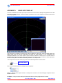
2. CURSOR REPORTING SERIAL DATA STRING OUTPUT
The Cursor Reporting option enables the user to send target position data to a remote, serially linked computer.
In the Setup menu, the user MUST first select which mouse button to use to activate the Cursor Reporting
output. Note that more than one mouse button may be selected.
By clicking on the Sonar display window with the selected Mouse button, the Range and Bearing position of the
mouse pointer is sent to the remote computer via the allocated COM Port. Therefore to report on the position of
a particular target, on the Sonar display hover the mouse pointer over the target and click with the Mouse button
to activate an output string. The output format of this string is described further on.
To configure a COM Port and enable the Cursor Reporting serial output, click on the ‘Com Port’ menu item in
the Setup menu. The Port can be configured in the ‘Auxiliary Output Port’ panel by clicking on the ‘Setup’
button. Ensure that the ‘Type’ is set to ‘Cursor’ if outputting only Cursor Reporting data strings, else set Type to
‘Aux + Cursor’ if also outputting the Sonar Aux Port data strings.
Issue 9
TIL – Eng – Spec – 016
Page 41 of 46
Tritech International Ltd
Micron Sonar OIM
Configure the ‘Auxiliary Output
Port’ for outputting the Cursor
Reporting data strings from a
surface COM Port.
Set Type to ‘Cursor’.
N.B. If also outputting Sonar Aux
Port Data then set as ‘Aux + Cursor’.
Cursor Reporting String Format
The data string that is output for the Cursor Reporting feature is as follows…
%M002D012200001IP+rrrrr+bbbbbIP+nnnnn+ppppp<CR><LF>
Bearing from +marker in 1/10ths degree.
Only applicable with Markers operation.
Range from +marker in decimetres.
Only Applicable with Markers operation.
Bearing from origin
in 1/10ths degree
Range from origin
in decimeters
Data type identifier
IP = Integer/polar
Button identifier
Left = “00”, Right = “01”, Middle = “02”
Slot reply header
Always “002D0122000”
Message identifier
%M = Marker message
from trackball button
Cursor Reporting with Markers operation
The Cursor Reporting function can be linked with the operation of the Markers (‘Markers On’ in the Setup
menu). If both Markers A and B are dropped onto the Sonar display then it is possible to acquire both the
absolute position of the moved marker (for instance Marker A) as well as it’s position relative to the other
marker (i.e. Marker B).
Using this 2 Marker operation, the +nnnnn and +ppppp fields in the Cursor Reporting string become active
(otherwise they are filled with 00000 as default).
Issue 9
TIL – Eng – Spec – 016
Page 42 of 46
Tritech International Ltd
Micron Sonar OIM
Example with Markers operation
Drop both Markers A and B on the Sonar display. Ensure that the Left Mouse button is enabled for the Cursor
Reporting as this is the mouse button that is used to move the Markers with a click and drag motion.
Pick up and move any Marker with the click and drag of the Left Mouse button. On the Mouse Up event, the
Marker is dropped and the Cursor Reporting string is output on the selected COM Port.
The screenshot above shows Marker B being dropped at the indicated position on the Sonar display. The
Cursor Reporting String output on the Com Port for this would be as follows…
Issue 9
TIL – Eng – Spec – 016
Page 43 of 46
Tritech International Ltd
Micron Sonar OIM
3. INPUT OF GPS DATA FROM A SURFACE COM PORT
There is option to display and log GPS data from an incoming NMEA type data string. To configure this option,
a COM Port must first be allocated and enabled for this purpose. This configuration is performed by clicking on
the ‘Com Port’ menu item in the Setup menu (see earlier). This will open the following dialog box…
Select a COM ‘Port’ number to
receive the incoming GPS data
strings. Then set the ‘Baud’ rate
to match the output rate of the
GPS device.
Ensure the Port is then ‘Enabled’.
Thereafter the GPS will be displayed
in the ‘GPS’ Popup form (enabled via
‘GPS Input’ menu item.
Click on the ‘GPS Input’ menu item in the Setup menu to enable the ‘GPS’ Popup form. This form will display;
Top Row (L->R)
:
Bottom Row (L->R) :
Latitude/Eastings, Longitude/Northings, Zone.
Course Over Ground, Speed Over Ground, Heading.
Also, on the GPS Popup form there are 2 controls;
The left ‘Settings’ Button is used to select and configure the GPS input port.
The right Led is for Diagnostics. It flashes Green when there is an incoming GPS packet. Otherwise it remains
Greyed out.
The ‘GPS Setup’ menu, accessed by clicking on the ‘Settings’ button, is where the NMEA 0183 message type
can be selected…
Click on ‘Settings’ button to
open GPS Setup panel.
All position data updates displayed in the GPS panel will be recorded when the logging function is used to
record device data and GPS data.
Issue 9
TIL – Eng – Spec – 016
Page 44 of 46
Tritech International Ltd
Micron Sonar OIM
The ‘GPS Setup’ panel contains 4 drop-down menus for selecting NMEA 0183 message types for
Latitude/Longitude, COG/SOG, Heading and setting System Time.
It is possible to set the System time via any of the listed NMEA messages and this will update the system clock.
This is only really beneficial if Log Data containing both Sonar and GPS position data is to be post-processed.
The right-hand side of the GPS Setup panel includes the option to convert and display the incoming Lat/Lon
positions in Eastings/Northings format using a UTM conversion. There is also facility to select the particular
Ellipsoid to apply in the UTM conversion equation.
Issue 9
TIL – Eng – Spec – 016
Page 45 of 46
Tritech International Ltd
APPENDIX D:
Micron Sonar OIM
VIDEO INPUT DISPLAY
If the PC is installed with a Video Input capture card then its source can be displayed alongside the sonar data
on the Micron software display. It therefore makes it possible to view camera images on the same screen as the
sonar image updates.
The Video Panel is enabled in the Setup menu. When enabled, the ‘Video Input’ panel will initially appear as a
floating panel which can then be moved about the screen (as shown above) or it can be docked to the
Left/Right/Top/Bottom of the Sonar window. When the Micron software is closed down or the Video Panel is
disabled its floating/docked position will be retained for the next time it is opened. Within the Video Input panel,
the video overlay can be re-sized and will always maintain a 4 x 3 aspect ratio.
In the Top-Left corner of the Video Input panel is the Video Setup button as shown below…
Video Setup button.
Click on the Video Setup button to display the pop-up options...
Source – Sets the Video Capture device via a drop-down ‘Source’ list. The list will display all capture devices
installed on the PC.
Configure – Configure various settings for the selected Source including brightness and contrast.
Issue 9
TIL – Eng – Spec – 016
Page 46 of 46