1
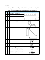
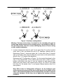
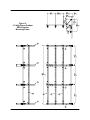
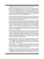
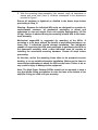
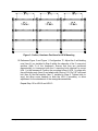
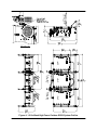
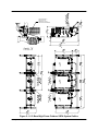
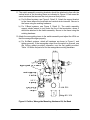
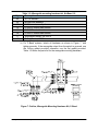
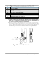
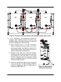
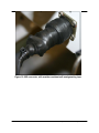
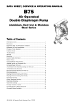
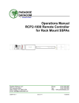
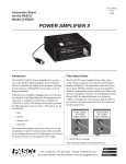
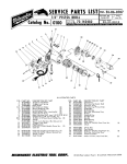
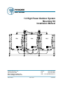
1:2 High Power Outdoor System
Mounting Kit
Installation Manual
Paradise Datacom LLC
328 Innovation Blvd.
State College, PA 16803 USA
Email: [email protected]
205075 REV B
Phone:
(814) 238-3450
Fax:
(814) 238-3829
Web: www.paradisedata.com
ECO 15239
03/05/2008
328 Innovation Blvd.
State College, PA 16803 USA
Telephone: 814-238-3450
Fax: 814-238-3829
E-mail: [email protected]
© 2008 Paradise Datacom LLC
Printed in the USA
2
205075 REV B
1:2 High Power Outdoor Mounting Kit Installation
Section 1: Overview
Introduction
This manual outlines the assembly and mounting procedure for a 1:2 High
Power Outdoor SSPA System.
Before beginning the assembly of the uni-strut mounting kit, verify that the kit
includes all of the items in Table 1-1. If any items are missing, please contact
Paradise Datacom with the part number and quantity of the shortage.
Paradise Datacom LLC
328 Innovation Blvd.
State College, PA 16803
Phone: 814-238-3450
Fax: 814-238-3829
e-mail: [email protected]
The following instructions describe the assembly of the uni-strut mounting kit,
and the installation of the High Power Outdoor SSPAs and associated switches
and waveguide assemblies. The system is intended to be free standing and
entirely self-supported once mounted on concrete decking.
It is important to give consideration to the following:
1. Structural integrity of the mounting deck.
2. Accessibility to all local user interfaces. (Ensure SSPA enclosure doors are
free to open to the latched position.)
3. Adequate cooling air, 8.00” minimum clearance must be maintained between
air intake and any surface that will inhibit air flow.
4. The High Power Outdoor SSPA should never be enclosed in such a manner
that airflow is restricted. Normal operating range is -40 to +60°C.
5. Proper weatherized sealing of all connectors.
Note: The High Power Outdoor SSPAs should not be positioned in such a
way that allows falling precipitation to enter the fans at the bottom of the
amplifier. Doing so could void your warranty.
1:2 High Power Outdoor Mounting Kit Installation
205075 REV B
3
Installation
Reference Table 1-1 and Figures 1-1 and 1-2 throughout the assembly of the
mounting frame.
Table 1-1: 1:2 System Mounting Kit Assembly Parts List (L205066-1)
ITEM QTY
4
PART NO.
DESCRIPTION
OUTLINE (NTS)
1
4
L21190-2
UNI-STRUT, 27”
2
4
L21190-14
UNI-STRUT, 36”
3
4
L21190-13
UNI-STRUT, 82.5”
4
4
B917
ANGLE, CONNECTOR,
5-HOLE
5
4
B940-1
CORNER BRACE, 7.5”
6
56
B911-1/2
NUT, SELF HOLD, 1/2
7
56
MS15795-819 WASHER, FLAT STD, 1/2”
8
40
MS35307-411 BOLT, HEX, 1/2-13X1.25,
SS
9
14
10
16
H119D
WASHER, SQUARE
CHANNEL, 9/16” HOLE
MS35307-418 BOLT, HEX, 1/2-13X2.75,
SS
205075 REV B
1:2 High Power Outdoor Mounting Kit Installation
Figure 1: Hardware configurations
Warning: The base struts (Item 1) included in the mounting kit must be
located and bolted securely to the decking prior to mounting the HPAs to
the mounting frame. This is to ensure that tipping does not occur during
or after system installation.
1. Locate 4 vertical struts (Item 2), and 3 cross struts (Item 3). Lay the 4 vertical
struts (Item 2) flat, one beside the next at 27” spacings, channel side up.
Referencing Figure 2, locate and place the 3 cross struts (Item 3) channel
side up as shown. Note: when locating the cross struts on the vertical struts,
allow for the 1 1/2” height of the base strut.
Reference the ‘B’ Configuration of Figure 1 for the required hardware for this
step. At the intersections of the vertical and cross struts, install 3 springloaded, self-holding nuts (Item 6) into the channel of each vertical strut.
Secure the cross struts to the vertical struts using a 1/2-13x2.75” hex head
bolt (Item 10), flat washer (Item 7), and square channel washer (Item 9) at
each position.
Note: Refer to the ‘A’ Configuration of Figure 1 for the hardware used
on the top-most junctures of the two vertical struts in the middle of the
frame. The switch assemblies will be mounted later and will be secured
using this hardware. At this time, do not tighten the hardware at these
junctions.
1:2 High Power Outdoor Mounting Kit Installation
205075 REV B
5
Figure 2:
1:2 High Power Outdoor
SSPA System
Mounting Frame
6
205075 REV B
1:2 High Power Outdoor Mounting Kit Installation
Check against the dimensions in Figure 2 to ensure the spacing is correct
and tighten all hardware at the junctures labeled ‘B’ in Figure 2.
2. Locate 4 5-hole angle brackets (Item 4). At the bottom of each vertical strut
install a pair of spring loaded self holding nuts (Item 6). Reference Figure 2
and the ‘E’ Configuration of Figure 1 for the required hardware. Using
1/2-13x1.25” hex head bolts (Item 8) and flat washers (Item 7), attach the
short side of the 5-hole angle bracket to the vertical strut such that the long
side of the angle bracket is in line with the bottom edge of the vertical strut.
Repeat for the other 3 vertical struts. Tighten all bolts.
3. The framework consisting of the vertical strut sections (Item 2) and the cross
strut sections (Item 3) should be checked dimensionally against Figure 2,
and for square-ness. Verify that all hardware is secured as stated in the
above steps before proceeding to Step 4.
4. Locate the 4 base struts (Item 1) and arrange them channel side up, spaced
as shown in Figure 2. Slide a pair of spring loaded, self-holding nuts (Item 6)
into the channels of each base strut. These will be used to secure the bolts
through the long side of each 5-hole angle bracket from Step 2. Raise the
frame to the upright position and set the vertical struts (Item 2) directly on
each base strut so that the back of each vertical strut is 7.5” from the back
edge of the base struts. Align the self-holding nuts in the base strut channels
with the holes in the long side of the 5-hole angle brackets. Secure as shown
in Figure 2, ‘E’ Configuration.
5. With the vertical strut framework mounted to the base struts, install one
spring loaded self holding nut (Item 6) in each vertical strut and one toward
the rear of each base strut. Position a corner brace (Item 5) as shown in
Figure 2 and align the corresponding self holding nuts to the hole locations
of the corner brace. Reference Figure 1, ‘E’ Configuration for the required
hardware. Attach each corner brace with a 1/2-13x1.25” hex head bolt (Item
8) and flat washer (Item 7). Tighten all bolts.
6. Slide a self holding nut (Item 6) in each of the base strut (Item 1) channels
approximately 6 3/4” from the front of each base strut. Referencing Figure 1,
‘B’ Configuration, mount the remaining cross strut (Item 3) to the base struts
(Item 1) using 3 1/2-13x2.75” hex head bolts (Item 10), and square channel
washer (Item 9). Tighten all bolts.
7. Reference Figure 1, ‘E’ Configuration of hardware. Secure two self holding
nuts between the top and middle horizontal struts using a 1/2-13x1.25” hex
head bolt (Item 8) and flat washer (Item 7) with each. This will be used to
secure the Isolator or RF IN switch assembly in Step 14.
8. Reference the ‘D’ Configuration of hardware in Figure 1. Install spring loaded
self holding nuts (Item 6) with 1/2-13x1.25” hex head bolt (Item 8) and flat
washer (Item 7) at each of the positions labeled ‘D’ shown in Figure 2. Do
not tighten at this time. These will be used to mount the HPAs to the frame.
1:2 High Power Outdoor Mounting Kit Installation
205075 REV B
7
9. With the mounting frame assembly fully erected, verify all framework is
square and cross strut (Item 3) locations correspond to the dimensions
provided in Figure 1.
Ensure all hardware is tightened as detailed in the above steps before
proceeding to Step 10.
Warning: Because the individual HPA units are designed for operation in
environmental extremes, all mechanical packaging is robust and
substantial in size and weight. Each unit weights approximately 145 lbs
(66 kg). Caution is advised during the mounting of each HPA to the framework assembly.
Mechanical support/lift is suggested for mounting of the HPAs. If
mounting is to be done without the benefit of mechanical assistance, no
fewer than 3 individuals should attempt installation. Two individuals
capable of supporting the HPA must participate in positioning the HPA on
the framework assembly while a third individual must be capable of
installing the associated mounting hardware. Review all steps before
proceeding.
At this time, anchor the mounting frame either to the prepared concrete
decking, or to any suitable alternative installation. Make sure the frame is
secure before attempting to attach the HPAs to the frame. Failure to do so
may result in injury or damage to the equipment.
Note: The High Power Outdoor SSPAs should not be mounted in such a
way that allows falling precipitation to enter the fans at the bottom of the
amplifier. Doing so could void your warranty.
8
205075 REV B
1:2 High Power Outdoor Mounting Kit Installation
Figure 3: Outline, Hardware Positions for HPA Mounting
10. Reference Figure 3 and Figure 1, Configuration ‘D’. Adjust the 6 self-holding
nuts (Item 6) you installed in Step 8 within the channels of the 3 cross strut
sections (Item 3) of the framework. Ensure that they are positioned
dimensionally to correspond with the 6 mounting bolts required to mount
HPA 1 to the framework. Position the mounting holes of HPA 1 to align with
the self holding nuts (Item 6) and attach with 6 sets of 1/2-13x1.25” hex head
bolt (Item 8) and flat washer (Item 7) installed in Step 8. Tighten bolts to
snug, but allow some freedom to slide the HPA if necessary, to allow
adjustment for the attachment of the waveguide assemblies.
Repeat Step 10 for HPA 2 and HPA 3.
1:2 High Power Outdoor Mounting Kit Installation
205075 REV B
9
DETAIL ’A’
RF OUTPUT
J2
P /N: L2 02 70 1-X
P /N: L2 02 7 01-X
RF OUTPUT
J2
MO DEL : XXX XXXXXXXXX
S /N: XXXX
Ku -Ba nd
So lid Sta te Po wer Amplifier System
P /N: L2 02 70 1-X
RF OUTPUT
J2
MODEL: XXXXXXXXXXXX
S/N: XXXX
Ku-Ba nd
Solid Sta te Po wer Amp lifier System
1:2 High Power Outdoor Mounting Kit Installation
205075 REV B
10
MODEL: XXXXXXXXXXXX
S/N: XXXX
K u-Ban d
S olid S tate P owe r A mp ilfie r Syste m
Figure 4: 1:2 Ku-Band High Power Outdoor SSPA System Outline
MODEL
S /N:
:
XXX XX XX
X
XXX
XXXX
X
P/
N:
LXXX
XX
X-X
SWITCH BRACKET S
ATTACH TO TOP
HORIZONTAL STRUT
USE EXISTING HARDWARE
P /N: L2 027 01-X
RF OUTPUT
J2
MODEL: XXXXXXXXXXXX
S/N: XXXX
Ku -Ba nd
So lid Sta te Pow er Amp il fier Sys tem
P/N: L2 02 701- X
RF OUTPUT
J2
MODEL : XXXXXX XXXXXX
S /N: XXXX
Ku- Band
S olid St ate Po wer Amp lifier Sy stem
P/N : L2 02 701 -X
RF OUTPUT
J2
MO DE L: XXXXXXXXX XXX
Ku- Ban d
S olid S tat e P ower Amp lifier System
S /N: X XXX
Figure 5: 1:2 C-Band High Power Outdoor SSPA System Outline
11
205075 REV B
1:2 High Power Outdoor Mounting Kit Installation
11. The switch assembly mounting brackets should be attached in-line with the
vertical struts of the mounting frame as indicated in Figure 4. Each uses the
same hardware that secures the strut pieces at that junction.
a) For Ku-Band systems, see Figure 4, Detail ‘A’. Attach the support bracket
to the frame where the horizontal and vertical struts intersect. Secure to
the frame using the existing hardware.
b) For C-Band systems, see Figure 5, Detail ‘A’. The switch assembly
support should extend to just under the fins of the termination, where it
should be attached to the switch assembly. Secure to the frame using the
existing hardware.
12. Attach the waveguide pieces to the switch assembly and adjust the HPAs so
that the waveguide aligns properly.
a) For Ku-Band systems, attach all hardware as shown in Figure 6, and
tighten securely. If the waveguide output from the switch is grooved, use
the O-Ring gasket provided; otherwise, use the flat gasket provided.
Table 1-2 shows the parts list for the waveguide mounting hardware.
Figure 6: Outline, Waveguide Mounting Hardware Kit, Ku-Band
12
205075 REV B
1:2 High Power Outdoor Mounting Kit Installation
Table 1-2: Waveguide mounting hardware kit, Ku-Band 1:2
Qty.
44
32
12
12
4
16
2
10
Description
#6 Flat washers
#6 Split-lock washers
6-32 hex nuts, small pattern
6-32x7/8” socket head screws
6-32x5/8” socket head screws
6-32x1/2” socket head screws
Waveguide Gasket, flat, WR75
O-Ring Gasket, WR75
b) For C-Band systems, attach all hardware as shown in Figure 7, and
tighten securely. If the waveguide output from the switch is grooved, use
the O-Ring gasket provided; otherwise, use the flat gasket provided.
Table 1-3 shows the parts list for the waveguide mounting hardware.
Figure 7: Outline, Waveguide Mounting Hardware Kit, C-Band
1:2 High Power Outdoor Mounting Kit Installation
205075 REV B
13
Table 1-2: Waveguide mounting hardware kit, C-Band 1:2
Qty.
88
64
24
24
2
38
2
10
Description
#10 Flat washers
#10 Split-lock washers
10-32 hex nuts, small pattern
10-32x7/8” socket head screws
10-32x5/8” socket head screws
10-32x1/2” socket head screws
Waveguide Gasket, full, CPRG-137
Waveguide Gasket, half, CPRG-137
13. Connect all cables and semi-rigid coax, beginning at the waveguide switch.
Make sure all connectors are oriented correctly, and that the pins align. Do
not attempt to force the connector into its receptacle.
14. Connect the isolator or RF IN Switch to the coax from the waveguide switch,
then slide the hardware (from Step 7) to secure the bracket in place. See
Figure 8. Tighten the hardware securely, then finish connecting all cables as
described in your schematic. All cables are labeled for easy identification.
Figure 8: Mount Isolator Bracket to Frame
14
205075 REV B
1:2 High Power Outdoor Mounting Kit Installation
Figure 9: Wrap all cable connections with weather-resistant tape or putty
15. As a precaution, all connections should be
wrapped with weather-resistant electrical tape,
provided. Make sure each connector is clean and
dry before applying the electrical tape.
M ODE
S/N:
L:
XXXX
XXXX
XXXX
XXXX
P/N:
LXXX
XXXX
a) Apply electrical tape to all MS connectors,
N-type connectors and any joins in the semirigid coaxial cables. See Figures 9 and 9a for a
representative outline which points out the connectors that should be weatherized.
b) Starting at the cable end, wrap the weatherresistant electrical tape around the connector
and overlap by half the width of the tape.
Continue wrapping until the connection mating
point is enveloped. Wrap an extra turn around
the base of the connector.
c) Press and smooth the tape with your fingers to
form a good seal. The tape surface should be
uniform in appearance with no visible gaps or
protrusions. See Figure 10.
1:2 High Power Outdoor Mounting Kit Installation
205075 REV B
Figure 9a: Wrap all joins
as well as connectors
15
Figure 10: MS connector, with weather-resistant self-amalgamating tape
16
205075 REV B
1:2 High Power Outdoor Mounting Kit Installation