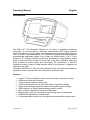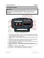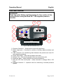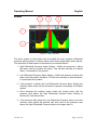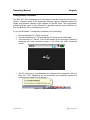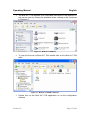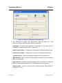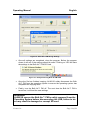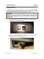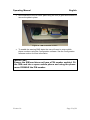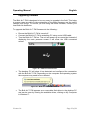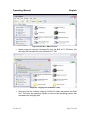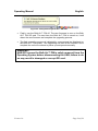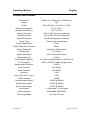
1
Operating Manual
BULK AIR™
AIR™ PM
Negative Pressure Monitor
Operating Manual
English
Certification
Bulk Air™ Limited certifies that this product met the published specifications at
the time of shipment. Bulk Air™ Limited further certifies that its calibration
measurements are traceable to the National Institute of Standards and
Technology (NIST).
Warranty
This Bulk Air™ Limited product is warranted against defects in materials and
workmanship for a period of one (1) year from the date of shipment.
Service
For warranty service or repair, this product must be returned to a Bulk Air™
authorised service facility. Contact an authorised distributor before returning this
product for repair.
Information in this document is subject to change without notice.
Copyright © Bulk Air™ Limited 2013. All rights reserved.
Bulk Air Limited
Unit 5 The Sunhill Centre
Fleets Lane, Rylstone, Skipton,
North Yorkshire. BD23 6NA.
www.bulkair.co.uk
Manufactured in U.K.
Version 1.0
Page 1 of 28
Operating Manual
English
Safety and Preparation for Use
CAREFULLY READ THE IMPORTANT SAFETY INSTRUCTIONS
AND NOTES INCLUDED IN THIS SECTION BEFORE USING
THE BULK AIR™ PM NEGATIVE PRESSURE MONITOR AND
ITS ACCESSORIES. SAFETY PAYS!
Within this section, the word ‘product’ specifically refers to the Bulk Air™ PM
negative pressure monitor and any of its accessories.
The intention of this section is to collect, in a single place, the most common risks
associated to the installation, operation and maintenance of this product. The
instructions are also repeated, with additional information, at the appropriate
points throughout this manual.
This product has been designed with user-safety as a priority and has been
proven to show reasonably safe operation provided it is installed, operated and
serviced in strict accordance with all the safety instructions included in its
manual.
Safety Instructions and Warnings
•
•
•
•
•
•
•
SAFETY PAYS! Safety instructions must be strictly followed during all
stages of installation, operation and service of this product. Failure to
comply with these precautions and warnings violates the safety standards
expected of users of this product.
If you have any doubts about how to use this product safely, contact your
authorised distributor at the address listed in this manual.
Retain these safety and operating instructions for future reference.
Identify and adhere to all warnings posted on the product.
Failure to comply with these instructions may result in serious personal
injury, including death, as well as significant property damage.
It is the installer’s responsibility to ensure the safe operation of ventilation
and filtration equipment. Carefully check installation, pressure test points
and alarm set points before operation.
Provide for fail-safe operation wherever an equipment malfunction could
lead to a hazardous situation.
Version 1.0
Page 2 of 28
Operating Manual
English
Electrical Shock Risks
THE MOST COMMON RISK ASSOCIATED WITH THE
OPERATION OF ELECTRICAL PRODUCTS IS ELECTRICAL
SHOCK.
•
•
•
•
•
•
•
•
•
•
•
•
•
Dangerous voltages capable of causing injury and death are present
during the operation of this product. Do not remove the covers while the
unit is plugged into a live outlet.
Always operate the unit in its proper horizontal orientation. Do not operate
the unit on its side as foreign objects or liquids may enter through the
printer slot, creating an unsafe condition.
Do not use this product if it has unauthorised modifications. Unauthorised
modifications may result in fire, electric shock and other hazards.
Do not install substitute parts or perform any unauthorised modifications to
this product.
This product must only be used with a mains supply fitted with a 3A fuse.
The product has a detachable, three-wire power cord for connection to the
power source. The exposed metal parts of the product are connected to
the power cord ground to prevent against electrical shock. Always use a
power cord which has a proper connected protective ground. Consult with
an electrician if necessary.
GFCI (Ground Failure Circuit Interrupter) protected outlets are often
available in working environments, particularly in proximity to water
sources. GFCI’s are generally regarded as an important defence against
electrocution. GFCI’s must also be tested regularly to verify their
functionality. Always consult an electrician when in doubt.
Do not use accessories not recommended in this manual as they may be
hazardous.
Always turn off the power to the product before connecting any cables to
the product.
To reduce the risk of fire and electrocution do not expose this product to
rain or moisture. Be careful not to spill liquid of any kind onto or into the
product.
Only use high quality cables and connectors that properly shield all high
voltage terminals.
Do not push objects of any kind into this product through openings as they
may come in contact with dangerous voltage points or short out parts that
could result in a fire or electric shock.
Operation of this product with line voltages other than those accepted by
the power supply can cause damage to the product and injury to
personnel.
Version 1.0
Page 3 of 28
Operating Manual
English
Introduction
The Bulk Air™ PM (Pressure Monitor) is the latest in pressure monitoring
technology. It uses the latest in thermally compensated ASIC digital pressure
sensors to achieve a highly stable and accurate pressure measurement down to
1Pa (1/10,000th of an atmosphere). Its’ rotationally moulded case combined with
polycarbonate bulkheads makes a very tough yet stylish product. The 5.7 Inch
full-colour TFT display provides crystal clear presentation of the pressure status
whilst a thermal printer provides a hard copy of all data. Additional effort has
been invested to ensure simple and future-proof PC connectivity; a USB 2.0
connection makes it easy to drag pressure data off the product or upgrade the
software in the field.
Ultimately the Bulk Air™ PM has been designed to be as simple and reliable as
possible in order to provide the user with years of useful service.
Features:
•
•
•
•
•
•
•
•
•
•
Large 5.7” colour display for ease of use and clarity of pressure results.
Simple and quick user interface.
Tough, impact resistant custom case.
In-built thermal printer for on-site hard-copies of pressure results.
Highly accurate digital pressure sensor with good long-term stability.
USB connector to simplify downloading pressure results.
Easy software upgrade for future-proof operation.
Battery back-up so unit continues to work during loss of mains power.
GSM/GPRS capabilities for SMS alerts.
Configurable alarm outputs for sounder/strobe and auxiliary mains switch.
Version 1.0
Page 4 of 28
Operating Manual
English
Front Panel Overview
WARNING!
Read the entire Safety and Preparation for Use section of this
manual before using the Bulk Air™ PM negative pressure
monitor.
9
8
7
6
1
5
2
4
3
Figure 1 - Bulk Air™ PM Front View
1) 5.7 Inch full-colour display – Clear results and user interface with a wider
viewing angle than normal displays. A 4mm thick polycarbonate protector
makes the display almost indestructible.
2) Thermal printer – On-site hard copy of results for every minute of every
hour.
3) Carry handle / support legs – Makes the product easy to carry and when in
use the product sits at an angle to improve screen visibility.
4) Paper feed button – Feeds paper out of printer and, if held down during
power-up, will perform a test print.
5) Printer opening lever – Makes changing printer paper VERY simple.
6) Power On/Off button – Also used to cancel menu changes and silence
alarms.
7) OK Button – Implements menu changes.
8) Down button – Used to navigate menu and decrement settings.
9) Up button – Used to navigate menu and increment settings.
Version 1.0
Page 5 of 28
Operating Manual
English
Rear Panel Overview
WARNING!
Read the entire Safety and Preparation for Use section of this
manual before using the Bulk Air™ PM negative pressure
monitor.
8
7
1
2
3
6
4
5
Figure 2 Bulk Air™ PM Rear View
1) Pressure Channel 1 – Simple push-on/pull-off pipe fittings.
2) Alarm output port – Connects to a series of auxiliary power switches and
alarms.
3) USB connector. For transferring data between the product and user PC
and upgrading software.
4) Power inlet socket – With fuse and spare fuse draw.
5) Rubber Feet – Ensures the product does not move during use.
6) Distributor plate – clearly identifies the product distributor.
7) SIM and SD Card cover plate – easily removed to change SIM or SD
Card.
8) Pressure Channel 2 – Optional extra for monitoring a second pressure
system.
Version 1.0
Page 6 of 28
Operating Manual
English
Un-Packing the Bulk Air™ PM
Before unpacking the Bulk Air™ PM, please ensure the packaging does not have
any signs of crush or impact damage. If there is visible damage to the packaging,
please contact your local distributor.
Always open the packaging with care; do not use a knife to cut the packaging
open as this may cause damage to the content.
Safely store the Bulk Air™ PM packaging for future use such as when
transporting or storing the Bulk Air™ PM.
Once open, the Bulk Air™ PM packaging should contain the following parts:•
•
•
•
•
•
•
•
Outer carton
Front protection packaging
Rear protection packaging
Bulk Air PM unit
Accessories packaging
Mains cable with European plug
Pressure tubing (2 x 5 meter lengths)
USB Cable (USB A to mini B cable)
If any of the above items are not present in your packaging, double check your
packaging then contact your local distributor.
Version 1.0
Page 7 of 28
Operating Manual
English
Getting Started
WARNING!
Read the entire Safety and Preparation for Use section of this
manual before using the Bulk Air™ PM negative pressure
monitor.
•
•
Ensure the Bulk Air™ PM is in good visible condition with no damage to
the front or rear of the unit. If the Bulk Air™ PM appears to be damaged,
contact your authorised distributor.
Place the Bulk Air™ PM on a flat and stable surface where the front
screen can be clearly seen and the buttons can be easily accessed by the
user.
WARNING!
The Bulk Air™ PM negative pressure monitor must only be
used OUTSIDE the contamination area to avoid the product
being exposed to contamination.
•
•
•
The product should be positioned so it is near to a mains supply and the
point of work where the pressure is to be measured. This is to prevent
long runs of tubes and cables which could pose a trip hazard and
compromise the contamination containment area.
Plug the mains power cable into the mains inlet socket at the rear of the
unit (see Rear Panel Overview). Before connect the plug end of the mains
cable into a mains outlet socket, ensure the mains cable is not damaged,
crushed or showing signs of ware.
Finally connect the pressure inlet pipes to pressure CHANNEL 1 at the
rear of the unit. It is recommended to use two pipes for pressure
measurement. The pipe connected to the NEGATIVE (-) inlet port at the
rear of the unit must be fitted to the negative pressure zone to be
monitored. The pipe connected to the POSITIVE (+) inlet port at rear of
the unit must be positioned vented to an area representative of the air
pressure outside the negative pressure zone. It is not recommended to
position the POSITIVE (+) inlet tube near windows, doors, fan-heaters or
anything that could cause un-representative localised pressure variations.
Version 1.0
Page 8 of 28
Operating Manual
English
Powering Up
To power-up the Bulk Air™ PM press and hold the POWER BUTTON (see Front
Panel Overview) on the front of the unit until the self-test screen appears.
It should be noted that the firmware version number is displayed at the top of the
self-test screen. It may be useful to know this when considering upgrading the
firmware.
Figure 3 - Self-test screen
During self-test the Bulk Air™ PM tests its’ hardware to ensure it is responding
correctly. It tests the following:
•
•
•
•
Printer
Real-time clock
SD Card
SIM Card
The appearance of a tick next to each of these icons demonstrates the hardware
is functioning correctly. If a cross appears next to any of the hardware icons refer
to the trouble-shooting section of this manual for possible solutions.
If the self-test reports no problems the Bulk Air™ PM advances to the next
screen automatically. If a problem is reported the self-test screen remains
displayed until the user presses the OK BUTTON.
Version 1.0
Page 9 of 28
Operating Manual
English
The next screen displays the next service date and the Bulk Air™ PM serial
number.
Figure 4 - Service Date and Serial Number Screen
It is important to have the product serviced at regular intervals to ensure correct
product operation. Contact you local distributor to arrange a product service.
The service screen will display for five (5) seconds before automatically
advancing to the next screen.
The next screen is the distributor logo screen; this is displayed for five (5)
seconds before the system goes to the main results screen.
Version 1.0
Page 10 of 28
Operating Manual
Main Results Screen
English
7
1
6
5
2
3
4
Figure 5 - Main Results Screen
The main screen presents the pressure data in a clear graph, showing the last 60
minutes of recorded pressures. Each bar of the graph represents the lowest
pressure difference measured during that minute. The colour of each pressure
bar will change depending on the alarm status. The main results screen is
composed of the following:1) Current differential pressure reading in Pascals (Pa). This value is updated
every second and will display both positive and negative differential
pressures, however only positive differential pressures will be displayed on
the graph.
2) High pressure alarm point. This point does not move; the graph is rescaled to fit. Differential pressures above the high alarm level are not
displayed above the top of the graph.
3) Low pressure alarm point. This point will change position depending on
the low alarm set point; it is scaled between the high alarm and the zero
pressure point.
4) Time axis. This shows the time at which the corresponding pressure
occurred. It scrolls every minute and displays the time at 15 minute
intervals.
5) Battery back-up level (showing fully charged). The number of bars
displayed indicates the present charge capacity of the battery back-up.
6) Mains power supply connected. If the mains power supply is lost this icon
changes.
7) GSM signal strength (showing fully charged). The number of bars
displayed indicates the GSM signal quality.
Version 1.0
Page 11 of 28
Operating Manual
English
Menu Overview
Pressing the UP BUTTON or DOWN BUTTN from the main results screen will
access the menu screens.
Figure 6 - Menu Password Screen
Before a user can access the menu screen the product requires a password to
be entered. The password consists of a four (4) digit number. The default
password for the product is ‘0000’. Each digit can be changed in-turn by using
the UP BUTTON and DOWN BUTTON to increment and decrement the number
respectively, pressing the OK BUTTON advances to the next password digit.
Following the successful entry of the password the product will display the first
menu option screen. If the password is entered in-correctly or the POWER
BUTTON is pressed the product will return to the main results screen.
Once in the menu system the POWER BUTTON can be used at any point to exit
the menu, back to the main results screen without modifying the last menu
setting. If no buttons are pressed for a period of 10 seconds the product will
return back to the main results screen without modifying the last menu setting.
The UP BUTTON and DOWN BUTTON are used to scroll through the menu
options and the OK BUTTON is used to select the menu option.
The selected menu option setting can be changed using the UP BUTTON and
DOWN BUTTON. Pressing the OK BUTTON will implement the change and
return to the main menu.
A full description of the menu options can be found in the Menu Descriptions
section.
Version 1.0
Page 12 of 28
Operating Manual
English
Menu Descriptions
Menu Icon
Description
High Alarm – Changes the high differential pressure alarm level. If
the differential pressure increases above the high alarm level the
product will alarm. The auxiliary mains switch will be turned off.
Low Alarm – Changes the low differential pressure alarm level. If the
differential pressure decreases below the low alarm level the
product will alarm. The auxiliary mains switch will be turned on.
Enable/Disable Printer – Selecting this menu option will toggle
between enabling and disabling the printer. If the printer is enabled it
will instantly print the pressure graph and summary data, this will
then be repeated every 60 minutes.
Displays the product serial number. This menu option is for
information only and cannot be changed. It is important to ensure
the serial number matches the serial number on the back of the
product.
System Time – This menu option enables the system time to be set.
The time format uses the 24-hour convention ‘hh:mm’. Due to
country variations the system does not adjust for day light/summer
time saving.
System Date – This menu option enables the system date to be set.
The date format used is ‘dd/mm/yy’. If an incorrect date is entered
(such as 30/02/13) the date reverts to its’ previous setting.
System Language – This menu option enables the system language
to be changed.
Version 1.0
Page 13 of 28
Operating Manual
Alarms
English
3
4
5
1
2
Figure 7 - Alarm Activation
The alarm system of the product can be divided into three systems; differential
pressure warning alarms, auxiliary mains switch alarm and product status alarms.
The operation of these alarms is described in more detail below:1. High Differential Pressure Alarm Setting – Whilst the pressure is above
this alarm level the product will alarm. This will also activate an external
alarm, if connected to the product.
2. Low Differential Pressure Alarm Setting – Whilst the pressure is below this
alarm level the product will alarm. This will also activate an external alarm,
if connected to the product.
3. If the pressure is below the Low Differential Pressure Alarm Setting the
auxiliary mains switch will be activated to operate a secondary air filtration
system.
4. Once activated the auxiliary mains switch will remain active until the
pressure rises above the High Differential Pressure Alarm Setting, at
which point it will de-activate.
5. If the pressure falls below the Low Differential Pressure Alarm Level the
auxiliary mains switch will activate until such time as the pressure rises
above the High Differential Pressure Alarm Level again (see 4).
Version 1.0
Page 14 of 28
Operating Manual
English
Printer
The Bulk Air™ PM uses the latest in embedded thermal printer which is very
easy to load with new paper rolls.
To fit new paper rolls to the printer do the following:-
Figure 8 - Opening the Printer
Pull down the small lever on the right of the printer. This will cause the printer
draw to open.
Figure 9 - Inserting Paper Roll
Once the printer draw is fully open; fit the new thermal paper roll so the paper
comes from the top of the roll, with the print side facing the buttons, as shown
above.
Finally, close the printer draw by gently pushing it shut. Once fully shut the lever
on the right of the printer will also close.
Version 1.0
Page 15 of 28
Operating Manual
English
Configuration Software
The Bulk Air™ PM is designed to be very easy to operate using the in-built menu
system. However some more advanced features can be accessed using the
simple configuration software which resides on the SD Card. The configuration
software can be used on any Windows™ operating system and should be run
from the Bulk Air PM by connecting it to a PC.
To run the Windows™ configuration software do the following:•
•
•
Ensure the Bulk Air™ PM is turned off.
Connect the Bulk Air™ PM to a desktop PC using a mini-USB cable.
Turn the Bulk Air™ PM on. The unit will power up as normal but instead of
displaying the main pressure screen it will show the USB connected
screen.
Figure 10 - USB Screen
•
The PC will show it has detected and configured the connection with the
Bulk Air™ PM. Depending on the computer and operating system the
computer may need to be re-booted.
Figure 11 - USB Device Found
Version 1.0
Page 16 of 28
Operating Manual
•
English
The Bulk Air™ PM appears as a removable flash-drive to the desktop PC
and can be seen by viewing the available drives; clicking on My Computer
in Windows™.
Figure 12 - Bulk Air™ PM Drive
•
To view the files on he Bulk Air™ PM, double click on the Bulk Air™ PM
drive.
Figure 13 - Bulk Air™ PM SD Card Files
•
Double click on the Bulk Air™ PM application to run the configuration
software.
Version 1.0
Page 17 of 28
Operating Manual
English
Figure 14 - Bulk Air™ PM Settings Editor Application
•
The Windows™ program will automatically load the Bulk Air™ PM
previous settings, which can then be easily modified:Language – Enables the selection of language to be used for the
Windows™ program and Bulk Air™ PM menu.
High Pressure alarm – Changes the high pressure difference alarm level.
Low Pressure alarm – Change the low pressure difference alarm level.
Job Description – Edit the description reference for the present job.
SMS Number 1 to 3 – Enter a cellular phone number to receive warning
SMS text messages.
Globe button – Opens an internet browser with at the Bulk Air™ PM web
page to access the latest Bulk Air™ PM firmware and user manual.
Folder button – Opens a folder showing saved pressure data stored on
the Bulk Air™ PM.
Version 1.0
Page 18 of 28
Operating Manual
English
Figure 15 - Bulk Air™ PM Saving Settings
•
Once all settings are completed, close the program. Before the program
closes it will ask if the settings should b saved. Clicking on YES will save
the settings to the Bulk Air™ PM SD Card.
Figure 16 - Safely Removing Bulk Air PM USB
•
Once the file has finished copying, ALWAYS safely disconnect the Bulk
Air™ PM from the operating system to ensure the operating system has
completed the copying task.
•
Finally, turn the Bulk Air™ PM off. The next time the Bulk Air™ PM is
turned on; it will load the new settings.
WARNING!
ALWAYS ensure the Bulk Air™ PM is safely removed from the
Operating System before disconnecting the USB, failure to do
so may result in damaged or corrupt SD card.
Version 1.0
Page 19 of 28
Operating Manual
English
Installing SIM card
The Bulk Air™ PM is capable of sending up to three (3) warning SMS messages
to remotely alert users of problems. In order to use this facility the Bulk Air™ PM
requires a registered SIM card to be fitted in the back of the unit:-
WARNING!
ALWAYS ensure the Bulk Air™ PM is disconnected from the
mains power supply and turned OFF before removing the
back panel.
•
First remove the SD card cover plate. This is done by removing the four
(4) posi-drive screws securing the plate.
Figure 17 - SD Cover Plate
•
Insert the pre-registered SIM card into the SIM card holder next to the SD
card holder. Gently push the SIM card fully in.
Figure 18 - Inserting the SIM Card
Version 1.0
Page 20 of 28
Operating Manual
•
English
Once inserted; fit the SD cover plate using the four (4) posi-drive screws to
secure the plate in place.
Figure 19 - SIM Card Fitted in Place
•
To enable the warning SMS alerts the user will need to enter mobile
phone numbers using the Configuration software. See the Configuration
software section for more information.
IMPORTANT!
Ensure the SIM card does not have a PIN number enabled. Fit
the SIM card into a spare mobile phone and using the phone
menu DISABLE the PIN number.
Version 1.0
Page 21 of 28
Operating Manual
English
Upgrading Software
The Bulk Air™ PM is designed to be very easy to upgrade in the field. This helps
to ensure users are able to take advantage of the latest firmware and the useful
features this brings. To ensure you are using the latest firmware, contact your
local Bulk Air distributor.
To upgrade the Bulk Air™ PM firmware do the following:•
•
•
Ensure the Bulk Air™ PM is turned off.
Connect the Bulk Air™ PM to a desktop PC using a mini-USB cable.
Turn the Bulk Air™ PM on. The unit will power up as normal but instead of
displaying the main pressure screen it will show the USB connected
screen.
Figure 20 - USB Connected Screen
•
The desktop PC will show it has detected and configured the connection
with the Bulk Air™ PM. Depending on the computer and operating system
the computer may need to be re-booted
Figure 21 - Bulk Air™ PM USB Detected
•
The Bulk Air™ PM appears as a removable flash-drive to the desktop PC
and can be seen by viewing the available drives; clicking on My Computer
in Windows™.
Version 1.0
Page 22 of 28
Operating Manual
English
Figure 22 Bulk Air™ PM Flash Drive
•
Simply drag and drop the firmware file onto the Bulk Air™ PM drive; this
will copy the firmware file onto the Bulk Air™ PM.
Figure 23 - Copying files to Bulk Air™ PM
•
Once the file has finished copying, ALWAYS safely disconnect the Bulk
Air™ PM from the operating system to ensure the operating system has
completed the copying task.
Version 1.0
Page 23 of 28
Operating Manual
English
Figure 24 - Safely Removing Bulk Air™ PM USB
•
Finally, turn the Bulk Air™ PM off. The new firmware is now on the Bulk
Air™ PM SD card. The next time the Bulk Air™ PM is turned on; it will
detect the new firmware and complete the upgrading process.
•
The final upgrading process is indicated by a percentage bar displayed on
the Bulk Air™ PM screen. This upgrading can take a few minutes. Once
complete the unit will continue to power up and operate normally.
WARNING!
ALWAYS ensure the Bulk Air™ PM is safely removed from the
Operating System before disconnecting the USB, failure to do
so may result in damaged or corrupt SD card.
Version 1.0
Page 24 of 28
Operating Manual
English
Product Specifications
Dimensions
200mm (h) X 300mm (w) X 300mm (d)
Weight
4kg
Power
90 to 264 VAC, 47 to 63 Hz, 125W
Working Temperature
5°C to +50°C
Storage Temperature
-20°C to +60°C
Working Humidity
20% to 80% RH non-condensing
Storage Humidity
10% to 90% RH non-condensing
Ingress Protection
IP54 Excluding power connector
Printer Type
Thermal direct line printing
Printer Paper Width
57mm
Printer Paper Roll Diameter
39mm
Printer Resolution
8 dots/mm (384 dots/line)
Display Size
5.7” (145mm)
Display Resolution
320 x 240 at 256 colours
Battery Back-Up
6 Hours
Data Storage Capacity
14 years of results based on 1Gb SD card
PC Connection
USB 1.0/USB 2.0 Mass Storage class
Measurement Pressure
±100Pa
Proof Pressure
±25,000Pa
Burst Pressure
±50,000Pa
Accuracy
±1Pa
Long Term Drift (1 Year)
±1Pa
In-Built Sounder
>95dB
Sounder Alarm Output
12VDC @ 500mA
Strobe Alarm Output
12VDC @ 500mA
NPU Control Output
12VDC @ 500mA
User Alarms
1 x High alarm, 1 x low alarm
Communications
Quad-Band GSM/GPRS
Field Up-gradable
Yes from SD Card
Version 1.0
Page 25 of 28
Operating Manual
English
SD Card Filing Structure
The Bulk Air™ PM stores logged pressure data and loads settings from the SD
Card installed in the back of the product. The files are stored in specific location,
below is an example of where the Bulk Air™ PM stores the files.
AUTORUN.INF
BULKAIR_0_15.HEX
BULKAIRPM.EXE
SETTINGS.TXT
SYSTEM
BULKAIR_PM.ICO
TITLE.BMP
DATA
2013_04
13-04-05.CSV
13-04-06.CSV
Figure 25 - Bulk Air PM SD Card Filing Structure
Version 1.0
Page 26 of 28
Operating Manual
English
EC Declaration of Conformity
In accordance with EN ISO 17050-1:2004
We
Bulk Air™ Limited
of
Unit 5 The Sunhill Centre, Fleets Lane,
Rylstone, Skipton, North Yorkshire. BD23 6NA.
In accordance with the following Directive(s):
2006/95/EC
The Low Voltage Directive
2004/108/EC
The Electromagnetic Compatibility Directive
hereby declare that:
Equipment
Negative Pressure Monitor
Model Number
Bulk Air™ PM
is in conformity with the applicable requirements of the following documents
Ref. No.
EN 60204-1
BS EN 61000-6-1
BS EN 61000-6-3
Title
Safety of machinery. Electrical equipment of machines.
General requirements.
Electromagnetic compatibility (EMC). Generic standards.
Immunity for residential, commercial and light-industrial
environments.
Electromagnetic compatibility (EMC). Generic standards.
Emission standard for residential, commercial and lightindustrial environments.
Edition/date
2006
2001
2001
I hereby declare that the equipment named above has been designed to comply
with the relevant sections of the above referenced specifications. The unit
complies with all applicable Essential Requirements of the Directives.
Signed:
Name:
Position:
Done at:
On:
Version 1.0
Geoffrey Swales
Managing Director
Rylstone, Skipton
11th March 2013
13
Document ref. No.
1234/13DOC
Page 27 of 28