1
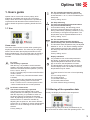
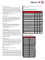
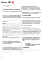
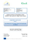
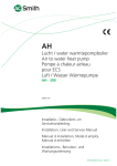
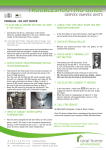
GB
User Manual
Vanvex Optima 180
Domestic Hot Water
Version 3.07 - 0310
Optima 180
Table of contents
Page
1. Users Guide
1.1 Use....................................................................................... 3
1.2 Altering of the operation data............................................... 3
1.3 Operating menu.................................................................... 4
1.4 Factory default scheme........................................................ 5
1.5 Defrost programme.............................................................. 5
2. Function
2.1 Description Optima180......................................................... 6
2.2 Extra capacity....................................................................... 6
2.3 Operation safety................................................................... 6
2.4 Warnings.............................................................................. 6
3. Maintaining
3.1 Communication box.............................................................. 7
3.2 Cooling System and fan....................................................... 7
3.3 Water circuit and tank........................................................... 7
3.4 Cancelling operation............................................................. 7
4. Fault finding
4.1 Highpressure switch............................................................. 8
4.2 Safety breaker for heating element...................................... 8
4.3 Heat pump will not run.......................................................... 8
5. Electric diagramme................................................................. 9
6. Flow diagramme................................................................... 10
Subject to Technical Modifications
2 Optima 180
1. Users guide
Optima 180 AC comes with a factory setup, which
enables an immediate start of the unit. The factory
setup is basic and must be adjusted to the operational
requirements and demands of the individual home, in
order to obtain the optimum operating benefit from the
unit.
1.1 Use
P3: The operating thermostat is pressed
The required domestic water temperature may
be set between 0 - 55 °C, which is heated by the
heat pump.
Factory setting: 52,0°C
+
+
Users menu
The value of a menu item is shown when pressing the
key/keycombination below. The value may be changed
with the arrows when the key/keycombination is held
down simultaneously. The control will return to standard
indication if no buttons have been pressed for app. 15
seconds.
P1: Level
The level key is pressed
With this key, it is possible to switch between:
standby, automatic operation, constant operation
and timer controlled constant operation. (Level 0,
level 1, level 2, level 3).
Level 0: The heat pump is now turned off and the
control is active.
Level 1: The fan only runs when domestic water
is heated.
Level 2: The fan also runs after the compressor
has stopped, providing extract to the home.
Level 3: The fan runs in a chosen period of time
- before it switches back to normal operation.
P2: Electric element ON
The electric element key is pressed
The heat pumps are supplied with an extra
heating element for heating the domestic water.
With this signal key, it is possible to switch on
the electric element for heating the domestic
water. By adjusting the set point to 1, the electric
element will turn on whenever needed. By
adjusting the set point to 0, the electric element
will not turn on if needed. At outdoor temperatures
below 0°C it is an advantage to use the electric
element.
Factory setting: 0
P4: Stop defrosting
The level and operating thermostat buttons
are pressed simultaneously
As a standard setting, the defrosting period
ends when the temperature has reached 10 °C.
During extraordinary operating conditions, it may
be necessary to change this temperature. The
temperature may be adjusted between 0-25°C.
Factory setting: 10,0°C
P5: The electric element
The electric element and the operating
thermostat keys are pressed simultaneously
The domestic water temperature may be adjusted
between 0 - 65 °C. The electric heating element
solely heats the top half of the container, while
the heat pump still heats the lower half of the
container.
Factory setting: 50,0°C
Display indication
It is possible to view various temperatures in
the display, by pressing the arrows until the
required temperature has been shown. After
app. 5 seconds, the temperature is shown.
The temperature is shown for app. 30 seconds
until the display returns to standard. Following
temperatures may be shown:
T4: Extra sensor for free use or forced operating
input
T5: Pre cooling surface
T6: Cooling surface
T7: Domestic water top
T8: Domestic water bottom
T9: Solar collector temp (accessory)
1.2 Altering of the operation data
Usually, the display shows the water temperature.
Press (arrow up) and (arrow down) simultaneously for
app.10 seconds in order to enter the operating menu. The
3 Optima 180
display will now show the first point E0 in the operating
menu. The operating menu will close and return to the
main menu if a button has not been pressed for 15 sec.
help heating the water when the intake air temperature
is below the temperature set in E10. The function is
activated when the value has been set to 2 (= fresh airoperation).
Factory setting: 0
E10: Operating in cold surroundings
When activating the function menu E9, the temperature at
which the compressor will stop, or the heater will assist,
may be set. The temperature is adjustable between 0-10
°C.
Factory setting: 5
If you wish to scroll through the operating menu, it may
be done by pressing (arrow up) or (arrow down). The
value of a point is shown when pressing (temp button).
The value may be changed with the (arrow up) or (arrow
down) while simultaneously pressing (temp button). The
control will return to standard indication if no buttons have
been pressed for app. 80 seconds.
1.3 Operating menu
E0: Factory default
If the system does not function as expected, even though
the setpoints have been adjusted, and the cause is
impossible to locate, it is recommended to note down the
settings in the schedule. Thereafter the setpoint must be
adjusted to 1 and wait until the control returns to standard
settings. Now all the setpoints have been changed to
the factory default. It is now possible to start all over and
adjust the set points.
Factory setting: 0
E2: T9 Set Temp
If the unit is connected to an under floor heating, this
setting controls the desired room temperature where
the under floor heating is installed. The temperature is
adjustable between 10-30 °C.
Factory setting: 21
E8: Disinfection function ON/OFF
By setting the point to 1, the electric heating element will
provide 65°C hot water, once a week, in order to disinfect
the tank.
Factory setting: 0
E9: Operating in cold surroundings ON/OFF
If the setting is 0 the heat pump will run as long as there
is a need of heat (= exhaust air-operation).
Using the heat pump when taking the admission air
from e.g. the cellar, there is an option of making the
compressor stop in case the room is getting to cold.
Instead, the electric heater will heat the water. The
function is activated when the value has been set to 1 (=
circulating air-operation).
It is also possible to automatically let the electrical heater
4 E13: Under floor min. Temp
With this setting the minimum tank temperature is set,
which will allow heat to be delivered to the under floor
heating circuit. The temperature is adjustable between
20-50 °C.
Factory setting: 35
E15: Hygrostat / stop unit
If the value is 0 the speed of the fans will change to 3
when the relative humidity is above the preset value of
the hygrostat. If the value is 1 the unit will stop when the
clip number 25 and number 26 are short circuiting.
Factory setting: 0
E16: Min. airflow
This value shows the minimum speed at which the fan is
permitted to run when operating. Notice that the cooling
system may be overloaded, resulting a drop out of the
high pressure switch, if the value has been set to high.
The value should not be chosen higher than necessary,
in order to secure a minimal airflow through the cooling
surface. Set between 0-100%.
Factory setting: 0
E17: Extended airflow ON
At 3rd speed, there is an option of making the unit step
down automatically to the 2nd speed, after a number of
hours, by adjusting to set 1. If the set point is adjusted to
0, the unit will run at the 3rd speed until a lower speed
has been selected manually.
Factory setting: 0
E18: Hour
If automatic step-down at 3rd speed is in use, the number
of hours at which the unit is to operate with forced air,
may be adjusted here. The set point may be adjusted
between 1 - 10 hours.
Factory setting: 3
E19: Solar collector/Under floor heating
If the setting is 0, a solar collector can be controlled.
If the setting is 1, an under floor heating may be
controlled. The set point may be 0 or 1.
Factory setting: 0
Optima 180
E20: Solar col hyst
If a solar collector has been connected, a temperature
difference may be set, this must be between the water
temperature in the solar collector and the operating
thermostat of the hot water tank, before the circulation
pump of the solar collector is running. The temperature
in the hot water tank cannot exceed 70°C with the use of
the solar collector.
The set point may be set between 0 - 5°C.
Factory setting: 5
E21: TX set
In order to avoid high operating pressures in the cooling
system, the system output must be reduced for the
remaining part of the heating period. This parameter
indicates the water temperature at which the reduction
should start. It may be set to 0-55°C.
Factory setting: 45
E23: Tmop
This value indicates the maximum permitted evaporation
temperature. This prevents overloading of the
compressor system at high ambient temperatures.
Adjust this value between 0 - 20°C.
Factory setting: 15
E25: Vent level 2
If an extended period of extraction from the building
is wanted, it is possible to change to level 2. The fan
will now run until another level has been selected,
regardless the need of hot water. This option is used to
set the speed at which the fan should run, when level
2 is selected. Please note that this setting also sets the
maximum fan speed when running in level 1. The speed
may be set to 0-100%.
Factory setting: 100
E26: Vent level 3
If extraction from the building at a specific length of time
is required, it is possible to change to level 3. The fan will
now run for the set period regardless the need for heating
water. Thereafter the system will return to level 2. This
menu option is used to specify the speed at which the
fans should run when the set period has been chosen.
The speed may be set to 0-100%.
Factory setting: 100%
E26:
Available function. Must at all times be 1
E45: dTair-set
Here it is possible to choose minimum cooling of the air,
while heating the water. The control will adjust the speed
of the fan to make sure the air will be cooled at the exact
temperature chosen. In case the control, due to technical
reasons, needs to cool the air, the value will be controlled
by the automatic function. When requiring a larger fan
speed, the value may be reduced. Remember though, the
fan will run faster, using more energy, if the values are set
to low.
Factory setting: 5
1.4 Factory default scheme
Factory defaults:
Datum
E0: Factory default 0
0
E2: T9 set temp 21
21
E8: Disinfection function ON/OFF
0
E9: Operating in cold surroundings
0
E10: Operating in cold surroundings
5
E13: Under floor min. Temp
35
E15: Hygrostat / stop unit
0
E16: Min. air flow
0
E17: Forced ON
0
E18: hours
3
E19: Solar collector/under floor heating
0
E20: Solar collector hyst
5
E21: TX-set
45
E23: Tmop
15
E25: Vent level 2
100
E26 Vent level 3
100
E45 dTair-set
Datum
5
1.5 Defrost program
T5 before coil °C
T6 in coil °C
15°
-3°
13°
-3°
11°
-3°
9°
-4°
7°
-4°
5°
-5°
4°
-5°
3°
-6°
1°
-7°
0°
-8°
-2°
-9°
-5°
-11°
-7°
-13°
-9°
-13°
-11°
-15°
-13°
-16°
-15°
-18°
-17°
-20°
-18°
-21°
-20°
-22°
5 Optima 180
2. Function
2.1 Function description Optima 180
The flow diagram shows the location of the sensors, while
the control circuit board shows the relay outputs and the
other outputs for connecting fan and control panel.
Usage of hot tap water heat pump
The heat pump is only intended to produce hot tap water
for domestic use within the specified temperature limits.
The Vanvex sanitary hot water heat pump is a complete
unit with a 185/285 litre hot water tank, extraction fans,
heat pump and also equipped with a complete electrical
equipment and five models are equipped with a heating
coil which is prepared for connection of a solar collector /
central heating.
Capacity
The Vanvex is capable of producing a hot water volume
of app. 380 Litres at 55°C. The actual volume depends on
the supplied fresh water temperature, air temperature and
the pattern of use of hot water. The additional electrical
heating element may be used to boost the capacity
whenever needed. The heat pump only uses app. 30% of
the energy compared to a conventional electric boiler.
Heat pump operation
The control starts the compressor shortly after hot water
has been tapped. The compressor will run until the entire
tank has been heated to the set temperature again.
Usually the heat pump can produce a sufficient amount of
hot tap water covering the needs of a common family.
Water heating:
When hot water is drawn off, the tank will be refilled
with cold water at the bottom. A sensor measures the
temperature at the bottom of the tank and starts the
compressor if the temperature has fallen 5°C below
the set temperature. The compressor stops, when the
water has been heated to the set temperature. While
the compressor operates, the fans run and circulate air
through the cooling surface.
Fan operation:
The fan may be set to run continuously, - even after the
compressor has stopped - by selecting level 2 or level 3.
This option may be chosen when the Vanvex is used as
an extraction system in the residential wet rooms. If the
input to T4 short circuits, the control is forced to run at 3rd
speed. This may be used in order to achieve more extract
in e.g. bathroom, while taking a shower. When breaking
the short circuit on the input pins to T4, the control will
return to its previous step.
6 Defrosting:
When the temperature difference between the
temperature upstream of the cooling surface and the
temperature of the cooling surface becomes too large
(as happens when ice is formed on the cooling surface),
the unit goes into defrost mode. The magnetic valve
MA 4 opens and the supply air fan stops until the ice
has melted and the cooling surface has reached a
temperature of app. 8°C. Then the magnetic valve closes
again and the supply air fan resumes operation.
2.2 Extra Capacity
If a situation should occur where the heat pump is not
capable of producing enough hot tap water, an extra
electrical heating element can be switched on. Doing
so, it is possible to heat up more water. It is possible
to set the desired temperature to which the electrical
heater should heat up the water. (Only use the electrical
heater when needed, as it uses more energy than the
compressor). The activation of the electrical heater is
done manually on the display.
2.3 Operating safety
High-pressure switch:
To prevent the compressor exceeding its range of
operation, there is an integral high pressure switch, which
interrupts when the pressure becomes too high. Activate
the red reset button once the cause of the error has been
identified. When the high pressure switch interrupts, the
red Genvex logo will flash until the red reset button on
the pressure switch is activated. In order to prevent a
repetition of a pressure switch error, the water may be set
2-3 °C lower.
Safety breaker for electrical heating element
If an error occurs at the heater, the safety breaker trips
and stops the heater in order to prevent the tank from
being overheated. Resetting the safety breaker may be
done by breaking the small knob in the centre.
(When working on the heat pump,
always make sure the power supply is
disconnected.
Any work on this unit may only be carried
out by trained personnel!)
2.4 Warnings
High-pressure switch:
When the pressure switch trips, the red light on the
display will light until the pressure switch is reset.
Optima 180
3. Maintaining
The following instructions must be followed in order to
ensure optimum operation of the Vanvex:
The power supply to the system must
always be switched off before opening the
Vanvex’s cover.
When the unit has been installed for the first time make
sure the water connections are checked after a few days
to make sure there are no leaks. Also check that the
condensate drain pipe is not blocked.
Environmental considerations
When the unit is being serviced or its operation is
cancelled, please make sure to follow the guidelines for
recovery and disposal of all materials according to local
procedures and laws.
3.1 Communication box
To allow Optima 180 to communicate with the computer
(data logger), CTS unit, the “Genvex Datalogger”
communication box must be mounted between the
control panel and the computer/CTS unit. The unit is sold
by Genvex.
3.2 Cooling system
Fan
Maintaining the fans is mainly periodicly cleaning of the
evaporator. Disconnect the flexible hoses from the top of
the unit and unscrew the top plate. Clean the fan with a
suitable brush. Do not remove the balancing blocks from
the impeller, as this will cause imbalance and with it more
noise and fan wear.
Risk of injury from sharp-edged fins! DO
NOT damage this fins!
Condensate drain:
When changing the filters in the autumn season check
the condensate drain and tray for blockage by dirt. Fill
water in the condensate tray and check that the water
runs out unhindered. Should this not be the case the
drain must be cleaned. At the same time make sure that
the plates of the evaporators are clean.
valve, which is fitted before the safety valve on the cold
water pipe, prevents the water from flowing back into
the cold water pipe. This means that the pressure in the
tank will increase to the maximum pressure permitted by
the safety valve, at which point it will open and allow the
surplus water to escape. If the safety valve did not open,
the tank would burst.
To make sure that the safety valve is working properly,
it should be inspected several times a year. To do this,
press the spring-loaded arm on the safety valve and
see if water comes out of the valve. Damage caused
by a blocked safety valve is not covered by the Genvex
warranty.
Anode:
In order to prevent corrosion of the enamelled hot water
tank, the tank is fitted with a magnesium anode with
a ¾“ screw plug. This anode has a life expectancy of
2-5 years. It is nevertheless important to check that
the anode is intact at all times. This should be done by
inspecting the anode every 2 years and replacing it if it
is corroded and measures only 6-10 mm in diameter. To
inspect the anode, turn off the power supply to the system
and remove the front cover. The hot water tank has to be
drained before the anode can be unscrewed. To do this,
turn off the cold water supply , attach a hose to the drain
valve to ensure the water runs to the nearest drain. When
draining the water from the tank, turn on a hot water tap
to prevent negative pressure in the tank. When the tank
is empty, the anode can be unscrewed and inspected.
When the anode has been fitted again, close the drain
cock and turn the valve water supply back on to fill the
tank with water. When the tank is full and the cover back
on, the power supply can be switched on again.
3.4 Demounting
The following actions must be taken:
Disconnect the power supply to the unit and disconnect
other connections. Shutoff the fresh water supply valve
and connect a drain hose to the drain valve in order to
drain the water. While draining, a hot tap water valve
should be opened to avoid under pressure in the tank.
The air duct connections are uninstalled and remaining
air channels must be closed to avoid condense water
entrance to the building.
3.3 Watercircuit and tank
Safety valve:
The installer have fitted a safety valve on the cold
water supply pipe for the hot water tank. This valve is a
protection of the tank against excess pressure when the
domestic water expands during heating. The non-return
7 Optima 180
4. Fault finding
4.3 The heat pump will not run!
The heat pump is equipped with the following safety
devices:
Please test if:
4.1 High pressure switch:
To prevent the compressor exceeding its range of
application, there is an integral high pressure switch,
which interrupts when the pressure becomes too high.
In case of interruptions (too high pressure) the red light in
the control panel will flash and the high pressure switch
will stop the heat pump. The red light lights. Restart
the equipment by manually resetting the high pressure
switch.
● power is connected?
● power is turned on at the wall plug?
● the water temperature is at set point?
● the temperature of the domestic water > 55° C
● the cable between controller and display is connected?
If this does not help locating the error, please contact
your local installer or service contractor.
For manually resetting the high pressure switch. The front
door can be removed by releasing the screws.
For RESET
press the
red button.
4.2 Safety breaker for electrical water
heater
The safety breaker protects the equipment against
overheating during heating with the electrical heating
element. The safety breaker is mounted on the heater. If
the adjusted value (90°) is exceeded the heating coil will
disconnect. It can be reconnected when the temperature
is below 90°. To do this, the power to the equipment must
be off, front door dismantled and the front cover of the
heating element dismantled. The reset button can now be
pressed.
Please notice: Be careful not to damage or tear the
cables to the control.
8 For RESET
press the
small white
pin in the centre.
Optima 180
Notes:
9 Optima 180
Notes:
10 Optima 180
Notes:
11 world wide ...
Denmark
Genvex A/S
DK - 6100 Haderslev
Tel.: +45 73 53 27 00
Fax: +45 73 53 27 07
E-Mail: [email protected]
Belgium
Artiklima bvba
B - 9220 Hamme
Tel.: +32 (0) 52 41 25 41
Fax: +32 (0) 52 41 29 66
E-Mail: [email protected]
Billund
Copenhagen
Hamburg
Ireland
ECO Systems Ireland Ltd
Co. Antrim BT54 6PH
Tel.: (UK 028) (ROI 048) +44 2076 8708
Fax: (UK 028) (ROI 048) +44 2076 9781
E-Mail: [email protected]
Croatia
Pichler & CO d.o.o.
10000 Zagreb
Tel.: + 385/ (0) 1/ 65 45 407
Fax: + 385/ (0) 1/ 65 45 409
E-Mail: [email protected]
Slovenia
Pichler & CO d.o.o.
2000 Maribor
Tel.: +386/ (0) 2/460 13 50
Fax: +386/ (0) 2/460 13 55
E-Mail: [email protected]
Great Britain
Total Home Environment Ltd
GB- Moreton in Marsh, GL 56 0JQ
Tel.: +44 (0) 845 260 0123
Fax: +44 (0) 1608 652490
E-Mail: [email protected]
Intelligent ventilation systems
from Genvex A/S
As ventilation specialists, we offer a product range that covers
all aspects of modern ventilation equipment, from passive ventilation units with highly effective counter current heat exchangers to units with integrated heat pumps that are extremely
energy-efficient for heating and cooling.
Austria
J.Pichler Lufttechnik GmbH
A-9021 Klagenfurt
Tel.: +43 (0) 463 / 3 27 69
Fax: +43 (0) 463 / 3 75 48
E-Mail: [email protected]
Published by Genvex A/S, Sverigesvej 6, DK-6100 Haderslev
12