1
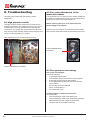
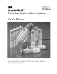
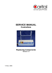
USER MANUAL
UK / Version 01.08.2014
OPTIMA 311
DISPLAY VER. 3.1 / PCB ES960C VER. 1.0B
Version 26.02.2014
COMBI 185 S/LS
Genvex A/S • Sverigesvej 6 • DK-6100 Haderslev • Tel.: +45 73 53 27 00 • [email protected] • genvex.dk
Table of contents
Page
1. Mounting Design....................................................................... 3
2. Control panel............................................................................. 4
3. Installation................................................................................. 4
4. Start-up....................................................................................... 4
5. Operating................................................................................... 5
5.1 Operating and changing data in the operating menu................ 5
5.2 Main menu................................................................................. 6
5.3 Date and time............................................................................ 6
5.4 Calendar.................................................................................... 7
5.5 User menu................................................................................. 7
5.6 Display menu............................................................................. 8
5.7 Info menu................................................................................ 10
5.8 Service menu...........................................................................11
5.9 Schedule for week program.................................................... 14
5.10 Schedule for defrosting ........................................................ 14
5.11 Schedule for set points ......................................................... 15
6. Function................................................................................... 16
6.1 Controlling Optima 311............................................................ 16
6.2 Extra capacity.......................................................................... 16
6.3 Operating reliability.................................................................. 16
7. Maintenance............................................................................. 16
7.1 Unit.......................................................................................... 17
7.2 Water circuit and boiler............................................................ 17
7.3 Dismantling/taking the system out of service.......................... 17
8. Troubleshooting...................................................................... 18
8.1 High pressure switch............................................................... 18
8.2 The safety thermostat of the immersion heater...................... 18
8.3 The system is not running....................................................... 18
8.4 Air faults................................................................................... 19
2
Subject to technical modifications of Optima 311
1. Mounting Design
1.1 Installation of the control panel
The control panel is designed to be mounted onto a flat
wall.
1.2 Mounting
Find the location on the wall where you will fix the control
panel and mark the screw-hole positions. A min. of four
screws must be used, the two bottommost and the two
topmost.
Mandatory Screw
Mandatory Screw
Screw
Screw
Mandatory Screw
A low-current cable 8 x 0.25 mm2 must be attached
between the unit and the control panel. 50 m is the
maximum cable length. The voltage drop for cable
lengths over 50 m is too high and can result in unreliable
operation.
How to mount the wall fixture:
First screw the fixture securely onto the flat wall and pass
the cable up from below.
Connect the low-current cable to the terminal block. Check
that the cable is connected to the same numbers at both
ends. (Between the control panel and the main circuit
board in the unit.)
Next clip the control panel to the wall fixture by guiding
it down from above, slightly slanting out at the bottom.
Finish by pressing in at the bottom so that it sits flat
against the wall. For demounting: pull the control panel a
little out at the bottom and lift up.
Mandatory Screw
Hold the wall frame against the wall and mark the
screw-hole positions. Drilling of holes, hole size and the
corresponding screws for fixing the panel depend on the
wall material.
Place the control panel in the fixtures and tilt it in against
the wall. The four support points in the corner of the
display must touch the wall to keep the display stable.
Support
Point
Support
Point
Support
Point
Support
Point
Pos.
Description
1
Panel housing
2
Front of panel
3
Pressure plate for display
4
Wall fixture
5
Glass for the display
A
Underneath the control panel there is an access for the:
A: Terminal block. Connection to main circuit board
Subject to technical modifications of Optima 311
3
2. Control panel
4. Start-up
The control panel must be mounted on an interior wall that
is centrally located in the home.
Since the control panel at the same time functions as a
room thermostat, it is important to observe the following:
The first time the system is started, the control panel display will show: “Choose language”.
• Do not expose the control panel to direct sunlight
• Do not place the control panel on an outer wall
• Do not recess the control panel in the wall
• Do not place the control panel over a heat source
A lamp close to the control panel can affect the light
sensor so that the control panel will not regulate the light
intensity as intended.
On the front of the control panel in the ring there are 7
keys that are used to operate the panel. The function of
the keys changes depending on the menu selected.
(More information is available under Operation).
There is an infrared movement sensor located under the
glass screen. Simply by moving your hand past the control panel you can bring up the menu for daily operating
options. (This function can be turned off:
See under Main menu/Display/Menu item 5).
The following are located at the bottom of the control
panel:
1: SD card
2: Room sensor
3: Light sensor
4: Mini USB port for connection to computer
1: The removable SD card contains all the control models
and versions that make the control panel compatible with
older versions. The SD card also contains all the languages, menus, help texts, symbols and collected data logs.
During the start-up procedure, the current versions are
installed in the control panel so that the control can function without the SD card. However, the help texts will not
appear in the display and the data logs will not be saved.
Click “Next” to switch between Danish, English, German
and French. Press “Enter” when the desired language is
shown in the display. The control panel will now load the
current program version in the selected language.
The display will show:
• Updating model (loading the current model)
• Wait 1.5 minutes (It takes approximately 1.5 minutes to
load the current version)
• Language load (91)
• Language OK
• Menu load (84)
• Menu OK
• Icon load (369)
• Menu OK
• Reset to default
• Restarting……..
• Optima 311 UK
The display will then change to:
• The Genvex logo
• Optima 311 UK
• Version number
D (Control panel): X.X
C (Main board): X.X
Finally, the display changes to daily operation and the
system is now in operation with the factory setting which is
only a basic setting.
The system is now ready to be adjusted with the most
optimal air flows and the operational desires and demands
for the dwelling in question, e.g. weekly operation,
temperatures etc. to achieve the most effective utilisation
and operation of the system.
4: In order for a computer to read the data logs,
the Genvex data logger program must be installed.
3. Installation
Please see the installation guide.
4
Subject to technical modifications of Optima 311
5. Operating
the User menu is set to ON.
Optima 311
K4 - Main menu
Use this function to enter the main menu and access the
sub-items Date and time, Calendar, User menu, Display,
Info operation and Service menu.
All Genvex combined ventilation units and domestic hot
water heat pumps of type Combi for dwellings are delivered with the Optima 311 control, which has a factory setting so that the system can be put into operation without
further setting. The factory setting is a basic setting that
should be adapted to the operating desires and demands
for the home in question to achieve the most effective
utilisation and operation of the system.
5.1 Operating and changing data in the
operating menu
Normally the symbols for daily operating options are
displayed and the following keys can be seen.
K1
K7
K2
K6
K5 - Filter
Use this function to reset the filter alarm. The key next to
the “Filter” symbol resets the alarm for filter change. To
reset the filter alarm, change the filters and hold down the
key with the “Filter” symbol until the exclamation mark in
the symbol disappears.
K6 - Information
Use this function to get an overview of the current operating condition, e.g. temperatures, fan settings, relay status/
function ON/OFF, alarms, timers etc.
Use the key next to the symbol “Info” to read the operating
condition of the unit. More information can be found in the
main menu section under the item Info operation.
K7 - Temperature
Use this function to set the room temperature. Press the
key next to the “Temperature” symbol to enter the desired
temperature between 10 and 30 °C.
The current temperature will be displayed at the centre of
the screen.
Press the key K4 to enter the main menu and sub-menus
and the following keys change function:
K3
K4
K5
K1 - Speed
Use this function to set the fan speed to levels 0-1-2-3-4.
Use the key next to the “Speed” symbol to change between the 4 speeds. The system can also be stopped by
holding down the key for 3-4 seconds on condition that
item 28 of the Service menu is set to ON.
K2 - Forced operation (Party mode)
Use this function/key to set the timer to party mode from
0 to 9 hours. If the number of hours is set to 0, speeds 3
and 4 will run until the speed is changed manually. If the
the number of hours is set between 1 and 9 hours, speeds
3 and 4 will automatically reconnect to speed 2 after the
number of hours configured.
K3 changes to “Arrow down ” and when changing the
setting to “÷”.
K4 changes to “Enter”. Press “Enter” to proceed through the menus and sub-menus.
K5 changes to “Arrow up” and when changing the setting to “+”.
K6 changes to “Exit”. Press “Exit” to return to the previous screen.
K7 changes to “Help”. Press “Help” to see a short guide to the current menu item.
The horizontal arrow in the menu shows the current
location. To save changes to a menu item, finish by
pressing “Enter”.
K3 - Immersion heater
Use the key next to the symbol “Immersion heater” to
change between + and ÷. If the symbol is set to “+”, the
immersion heater will automatically engage as required.
If the symbol is set to “÷”, the immersion heater will not
engage, even if required. It is an assumption that item 3 in
Subject to technical modifications of Optima 311
5
5.2 Main menu
There is a “Book” symbol at the bottom centre of the
screen with the daily operating options. Press this key to
enter the main menu.
Date and time
(item 4.3)
Calendar
(item 4.4)
User menu
(item 4.5)
Display
(item 4.6)
Info operation
(item 4.7)
Service menu
(item 4.8)
5.3 Date and time
Use this function to set the date and time.
01 Hours
Enter the current hour here.
When changing between summer and winter time you
have to set the time one hour forward or back manually.
02 Minutes
Enter the current minute here.
03 Weekday
Enter the current weekday here.
“Arrow down” or “Arrow up” will change the symbol to a
horizontal arrow that shows the current location.
04 Date
Enter the current date here.
05 Month
Enter the current month here.
06 Year
Enter the current year here.
Weekday
Press “Enter” to access the sub-items of the current menu.
Press “Arrow down” or “Arrow up” again to select the required sub-menu item. When the horizontal arrow is next
to a sub-menu item, the 2 lines will change place, the font
sizes will change and the text “Set” will be added. Pressing ”Enter” next to the selected sub-menu item will change
the background of the item to grey. Use the ”+” and ”÷”
keys to change the current value. Press “Enter” again to
save the change.
Monday
Tuesday
Wednesday
Thursday
Friday
Saturday
Sunday
If no changes are required, press “Exit” to go back out of
the menus. Press “Help” to see a short guide to the menu
item. Press one of the keys to exit the help program.
After a short period of non-activity, the control will automatically exit the programs.
6
Subject to technical modifications of Optima 311
Month
1
2
3
4
5
6
7
January
February
March
April
May
June
July
August
September
October
November
December
1
2
3
4
5
6
7
8
9
10
11
12
5.4 Calendar
Use this function to configure the setting of each day of
the week. Each day can be configured to run with different
fan speeds as required. You can copy the configuration
from one day to another. You can choose ON or OFF here,
i.e. if for a period of time there is nobody home, the daily
settings can be turned off and the system will run according to a manual setting, e.g. level 1.
01 - Calendar
Choose between controlling the system manually or controlling the speed (air exchange) and temperature automatically according to a fixed day program. If the menu
item is set to OFF, the system will be controlled manually
according to the speed and temperature selected.
If the menu item is set to ON, the system will be controlled
according to the day programs entered in the menu items
02 to 08.
Setting option: ON/OFF.
Factory setting: OFF.
02 - Monday
Up to 10 switching times can be entered for one day. The
times can be entered in random order. Enter the hours in the
first column, the minutes in the second and the speed in the
third column. Use the fourth column to enter the temperature
difference by which the temperature should be lowered.
Example: If the temperature is set to 21 °C and you enter
– 2.0 °C, the system will aim at 19 °C.
If the speed has been changed manually on the key under
daily operation, the program will return to the day program
when the next switching time is passed.
Examples of a day program:
01 07:30 H3 -0,0
02 09:15 H1 -1,0
03 17:00 H3 -0,0
04 18:00 H2 -0,0
05 23:30 H2 -2,0
It is not necessary to use all switching times. If the line is
marked by 0, it will be skipped by the control.
03 to 08
These days can be filled in individually in the same way as
under item 02.
09 Copy day
Use this menu item to copy one day to another, where the
same switching times, speeds and temperature lowering
are required.
For example: From Thursday to Tuesday.
5.5 User menu
01 - Temperature
Here the room temperature can be set. The temperature
sensor is mounted in the control panel.
Setting option: between 10 and 30 °C.
Factory setting: 21 °C.
02 - Domestic water
Here it is possible to set the desired domestic hot water
temperature.
Setting option: between 10 and 55 °C.
Factory setting: 52 °C.
03 - Immersion heater
By configuring the set point to ON, the immersion heater will
automatically engage when there is a need. If the set point
is configured to OFF, the immersion heater will not engage,
even if there is a need.
When the fresh air temperature is below 0 °C, it is recommended to connect the immersion heater as a supplement to
the heating of the domestic hot water and thereby reduce the
heating time.
Setting option: ON/OFF.
Factory setting: OFF.
04 - Timer levels 3 and 4
At speeds 3 and 4, the system will automatically reconnect
to speed 2 after the number of hours set in item 17 of the
Service menu by configuring the set point to ON. If the set
point is set to OFF, the system will run at speed 3 or 4 until
it is manually changed to another speed. The timer can
also be operated directly on the key next to the symbol for
“Party mode” on the screen for daily operating options.
Setting option: ON/OFF.
Factory setting: OFF.
05 - Change filter
A filter timer is built-in counting how long the system has
been running since the last change of filter. The set point
can be set between 1-6, which corresponds to 1-6 months.
It is recommended that the set point should initially be set
to 3, corresponding to 3 months.
If the filters are too dirty after the period configured, set
the set point to a lower number. If it is not necessary to
change the filters after the configured period, the set point
can be set to a larger number.
When the timer reaches the configured value for the
change of filter, the alarm “Change filter” will flash at the
top of the screen saver.
When the filters have been changed, return to the screen
with daily operating options and hold down the key for the
“Filter” symbol until the exclamation mark disappears and
the system returns to normal operation.
Setting option: between 1 and 6 months.
Factory setting: 3 months.
Subject to technical modifications of Optima 311
7
5.6 Display menu
The menu item with the “Display” symbol.
Use this function to configure the following sub-menu
items:
06 - Auto lightness
In the display there is a movement sensor.
Setting option: ON/OFF.
Factory setting: ON.
01 - Language
Choose between several different languages in the display.
07 - Lightness day
Use this to enter the maximum brightness level for the
control panel when the room is fully lit.
Setting option: between 0 and 100 %.
Factory setting: 100 %.
02 - Program info
This menu shows which Optima is fitted on the system
and its version number:
Example: Optima 311 UK D: 3.1 C: 1.0
D represents the version number of the control panel.
C represents the version number of the main board.
08 - Lightness night
Use this to enter the minimum brightness level for the
control panel when the room is in complete darkness.
Setting option: between 0 and 100 %.
Factory setting: 30 %.
03 - Screen saver.
The following settings can be selected here:
0: Screen saver off (daily operating options are displayed)
1: Screen saver off, but with light dimming
2: Room temperature + light dimming
3: Clock + light dimming
4: Clock and room temperature + light dimming
5: Black screen + light dimming
Setting option: between 0 and 5.
Factory setting: 3.
04 - Pause time
Use this to set the period from no operation of the symbols
on the screen for daily operation until the screen automatically returns to the screen saver. From daily menu
to screen saver variable from 1 to 10 minutes. The other
automatic return connections cannot be adjusted. If no
key has been pressed within the time intervals indicated
below, it will automatically return to the previous screen:
-Change in menu item back to menu item = 30 seconds
-From menu item to main menu = 2 minutes
-From menu item to daily menu = 2 minutes
Setting option: between 1 and 10 minutes.
Factory setting: 10 minutes.
05 - Auto wake-up
It is possible to deactivate the “Auto wake-up” function,
where you can change from the screen saver to the
screen with the symbols for the daily operating options by
moving your hand past the control panel.
If the function is set to OFF, press any key to display the
daily operating options.
Setting option: between 0 and 4.
Factory setting: 1.
”0” OFF
09 - Lightness day screen saver
Use this to enter the maximum brightness level for the
screen saver when the room is fully lit.
Setting option: between 0 and 100 %.
Factory setting: 50 %.
10 - Lightness night screen saver
Use this to enter the minimum brightness level for the
screensaver when the room is in complete darkness.
Setting option: between 0 and 100 %.
Factory setting: 0 %.
11 - Reset to factory settings
If the set points are configured so that the system does
not function as expected and the cause cannot be established, there are 2 different options to reset the menu
items to the factory settings.
- Press 1 to change all menu items to the factory settings
except for the menu items for Speed (Level), Filter timer,
Calendar and Defrost temperatures.
- Press 2 to change all menu items to the factory settings.
Note: Before performing a reset, ensure that the currently
entered values are noted in the “Schedule for set points”.
Setting option: between 0 and 2.
Factory setting: 0 mode.
12 - Safety menu
It is possible to prevent access to selected main menu
items so that they can only be changed with a password,
which is a 4-digit figure. The first time, press 4 times 0 and
then “Enter”. Items 13 to 18 will open. Select the password
in item 18, which will also be the password to access the
menu items 13 to 18 in future.
”1” Max sensitive
”2” Level 2
”3” Level 3
”4” Least sensitive
8
Subject to technical modifications of Optima 311
13 - Date and time
If this item is set to ON, it will not be possible to enter the
menu for Date and time without using the selected password in item 18.
Setting option: ON/OFF.
Factory setting: OFF.
14 - Calendar
If this item is set to ON, it will not be possible to enter the
menu for Calendar without using the selected password in
item 18.
Setting option: ON/OFF.
Factory setting: OFF.
15 - User menu
If this item is set to ON, it will not be possible to enter the
User menu without using the selected password in item 18.
Setting option: ON/OFF.
Factory setting: OFF.
16 - Display
If this item is set to ON, it will not be possible to enter the
menu for Display without using the selected password in
item 18.
Setting option: ON/OFF.
Factory setting: OFF.
17 - Service menu
If this item is set to ON, it will not be possible to enter
the Service menu without using the selected password in
item 18.
Setting option: ON/OFF.
Factory setting: OFF.
18 - Password
Enter the selected password here and use this also in
item 12 to enter items 13 to 18. If you forget your password, contact Genvex Service department for assistance.
To change the password, enter a new password in this
item and press “Enter”. The password has now been
changed.
5.7 Info menu
The Info menu provides an overview of the current operating status of the system. If you want to see the operating
status of the system over a period of operation, connect
the control panel to a computer and use the Optima data
logger program. The system monitors the operating status
every minute and stores the data for up to one year on the
SD card.
Current temperature
Press “Enter” next to the Info menu. The first screen displayed shows the current temperatures.
T1
Supply air
T2
Room
T3
Fresh air
T4
Exhaust air
T5
Before evaporator
T6
Evaporator
T7
Boiler, bottom
T8
Boiler, top
T9
Extra sensor
Current fan speed
Press “Arrow down” to display the current fan speeds and
the opening of the bypass damper and of the water valve.
Supply air
in %
Extract air
in%
Bypass damper
in %
Water valve
in %
Current setting of operation relays
Press “Arrow down” again to display the current status of
the operation relays.
R1
Compressor
R2
Immersion heater
R3
Electrical after heating
R4
Defrosting
R5
Domestic water
R6
Room
R7
Extra cooling
R8
Auxiliary relay 8
R9
Auxiliary relay 9
Subject to technical modifications of Optima 311
9
Current list of alarms
Press “Arrow down” again to display the current alarms.
An alarm it is activated if ON appears beside it. At ON
there is an alarm, which can also be seen on the screen
saver and the display for daily operating options. At the
top it says “Alarm”. The information menu shows the type
of alarm. When the timer for changing filter reaches the
set value, the alarm “Change filter” will flash at the top of
the screen saver.
The alarm will read OFF when the error has been
corrected or the filter is changed and reset.
Alarm
Status
Error at „ON“
Control
stopped
ON/OFF
Filter not changed after 14 days/ Frost protection
error/The system is equipped with an external
switch between terminals 28 and 29. “Alarm” will
be displayed when these are short-circuited and
the system has stopped.
Change filter
ON/OFF
The filters should be changed.
Frost
protection
ON/OFF
The temperature of the water after heater is too
low (frost danger).
Com error
ON/OFF
The control panel cannot communicate with the
main board (between display and printed circuit
board).
Pressure
switch
ON/OFF
The high pressure switch is disconnected due to
excessive pressure in the refrigerant circuit.
Hour counters (2 pages)
Press “Arrow down” again to display the hour counters,
which count from the day the system is put into operation.
The figures shown should be multiplied by 10. This shows
how many hours the system has been running, how many
hours the system has run at the various speeds and how
many hours the relays have been connected (ON).
Total time
Level 0
Level 1
Level 2
Level 3
Level 4
Relay 1 Compressor
Relay 2 Immersion heater
Relay 3 Electrical after heating
Relay 8 Help funktion
Relay 9 Help function
Press Exit to return to the main menu.
5.8 Service menu
Use this function to configure the following sub-menu
items.
10 - Level 1 Supply air
Level 1, which is the lowest speed, is usually used when
there is nobody home. Both fans can be configured independently of each other for all levels so that the air flow in
the supply air and in the extract air is equal, which provides optimal operation.
The adjustment of the system must be performed with
specialised air measurement equipment and can be performed without the use of the main regulating damper.
It is not recommended to configure the air flows without
expert advice. Incorrect configuration can lead to major
energy consumption or unpleasant indoor climate.
Setting option: between 0 and 100 %.
Factory setting: 30 %.
11 - Level 2 Supply air
Level 2 is the recommended speed of the system in order
to provide the optimal indoor climate and it should be adjusted to the ventilation requirement of the home.
Setting option: between 0 and 100 %.
Factory setting: 50 %.
12 - Levels 3 and 4 Supply air
Level 3 is the highest speed that can be configured. It is
used e.g. if there are many guests or there is a lot of activity in the kitchen.
Setting option of level 3: between 0 and 100 %.
Factory setting of level 3: 75 %.
Level 4 is used mainly in summer to lower the indoor
temperature. Remember that a higher air exchange rate
increases the energy consumption.
Setting option of level 4: cannot be configured.
Factory setting: 100 %.
13 - Level 1 Extract air
The fan speed is adjusted until the same air flow is
achieved as the supply air on level 1.
Setting option: between 0 and 100 %.
Factory setting: 30 %.
14 - Level 2 Extract air
The fan speed is adjusted until the same air flow is
achieved as the supply air on level 2.
Setting option: between 0 and 100 %.
Factory setting: 50 %.
15 - Levels 3 and 4 Extract air
The air flow of level 3 is adjusted to the same air flow as
the supply air on levels 3 and 4 (item 12).
Setting option of level 3: between 0 and 100 %.
Factory setting of level 3: 75 %.
Setting option of level 4: cannot be configured.
Factory setting: 100 %.
10
Subject to technical modifications of Optima 311
16 - (T2) Fine tuning
It is possible to fine tune the room sensor of the control
panel so the correct current room temperature is displayed.
Setting option: between -5 and 0 °C.
Factory setting: -3 °C.
23 - Regulation electricity
If an electrical preheater or an electrical after heater is installed, it may be necessary to adjust the regulation time.
Setting option: between 1 and 30 minutes.
Factory setting: 3 minutes.
17 - Timer levels 3 and 4
If automatic reconnection is used for speeds 3 or 4, you
can enter how many hours the system should run on level
3 or 4 before it automatically returns to level 2. The set
point can be configured between 1 and 9 hours.
Setting option: between 1 and 9 hours.
Factory setting: 3 hours.
24 - Min. Air - exhaust
The minimum air flow for exhaust is set here.
The heat pump will not start with exhaust air flow below
this setting.
Setting option: Between 0 and 100 %.
Factory default: 30%.
18 - Filter/stop
To ensure that the filters are changed when the alarm
“Change Filter” flashes on the screen of the control panel,
the set point can be configured to ON. The system will
then stop automatically after 14 days if the filters have not
been changed.
If this precaution is not required, the set point can be
configured to OFF and the system will continue to operate.
Setting option: ON/OFF.
Factory setting: OFF.
25 - Electrical heating coil
Here you enter whether the installation is fitted with an
electric heating coil:
0 = No electrical heating coil installed
1 = Electrical reheater installed
2 = Electrical preheater installed
Setting option: 0-2.
Factory setting: 0.
19 - Immersion heater
If item 3 in the Service menu is set to ON and the key on
the control panel for the immersion heater is activated, the
immersion heater will heat up the domestic water in the
upper part of boiler to the set temperature.
Setting option: between 0 and 65 °C.
Factory setting: 50 °C.
20 - Disinfection
If the item is configured to ON, once a week regardless of
the temperature setting the domestic water will be heated
up to 65 °C by the immersion heater to disinfect the boiler.
Setting option: ON/OFF.
Factory setting: OFF.
21 - Heating air
The default setting of the control is OFF to prioritise domestic water heating before room heating. To change the
priority, the set point must be configured to ON.
Setting option: ON/OFF.
Factory setting: OFF.
22 - Regulation water
If a water after heater with a motor-operated valve is
installed in the system it may be necessary to adjust the
regulation time.
The less regulation time, the faster the motor-operated
valve will regulate.
Setting option: between 1 and 250 seconds.
Factory setting: 20 seconds.
26 - Solar collector (ΔT) hysteresis
If a solar collector is connected to the coil of the boiler,
enter the temperature difference between the temperature
in the solar collector (T9) and the domestic water temperature (T8) to be reached before the solar pump should start.
The solar pump will not stop until T9 is equal to T8.
Under any circumstances the solar pump will stop when
T8 has reached a temperature of 60 °C.
Setting option: between 0 and 5 °C.
Factory setting: 5 °C.
27 Help function
This function can be used for the following:
Setpkt.
Function
0
The relay is off.
1
The relay is on when the system is running. This can e.g. be used
to open and close the fresh air damper and the exhaust air damper.
2
The relay is on when extra heat is required or when the circulating
pump should run when heating with water after heating is required.
3
The relay is on when the alarm “Change filter” is active. This can be
used to activate an external alarm.
4
The relay is on when extra cooling is required. This function is used
if a preheater is also fitted to the system.
5
The control can handle an earth heat exchanger by a damper. The
relay will be on for one of the following two conditions:
•
The outdoor temperature, sensor T9, is lower than the value
configured in item 37 (frost protection temperature, typically
set at 5 °C).
•
The outdoor temperature, sensor T9, is more than 1° above
the temperature configured in item 1 and 1 ° above the current room temperature.
Setting option: between 0 and 5.
Factory setting: 0.
Subject to technical modifications of Optima 311
11
28 - System stop
Here you choose if it should be possible to stop the system by pressing the key for speed (K1) in the operating
menu for 3-4 seconds. If the set point is OFF, the system
cannot be turned off.
Setting option: ON/OFF.
Factory setting: OFF.
29 - Stop defrosting
As default the defrosting period ends when the evaporator
has reached a temperature of 5 °C. It may be necessary
to change this temperature to a higher value under special
operating conditions where the evaporator is not
completely defrosted.
Setting option: between 0 and 15 °C.
Factory setting: 5 °C.
Please note: It is not recommended to configure the item
without expert advice.
30 - Compressor start/stop
The default temperature difference between start/stop
compressor is ± 0.4 °C. It is recommended to change the
temperature difference under special operating conditions.
Setting option: between 0.1 and 1.0 °C.
Factory setting: 0.4 °C.
Please note: It is not recommended to configure the item
without expert advice.
31 - Constant ON
If the other heating system of the home is not connected
to the heat pump system, the other heating system, e.g.
furnace, can stop the heat pump so that the heat pump
system with heat exchanger only blows preheated air
into all rooms. This will cause increasing problems with
draught as the temperature falls outside. Systems without
heat exchangers will blow fresh air directly in. Configuring
the set point to ON will disconnect the room sensor.
The heat pump will always operate and blow in warm air
when the fresh air temperature is below the temperature
configured in item 32.
If the set point is configured to OFF, the room sensor will
regulate the heat pump regardless of the fresh air
temperature.
Setting option: ON/OFF.
Factory setting: OFF.
32 - Constant
If ON is selected in item 31, the desired fresh air temperature can be set.
Setting option: between 0 and 10 °C.
Factory setting: 5 °C.
33 - Reduction
For very low fresh air temperatures, lowering the supply
air flow is recommended in order to improve the operating
conditions of the heat pump and to also achieve a higher
supply air temperature, even though the same air flow will
be extracted.
If the set point is configured to ON, the supply air flow will
12
be lowered when the fresh air temperature falls below the
temperature configured. If the set point is configured to
OFF, there will be no reduction of the supply air flow. This
configuration applies when a preheater is installed in the
fresh air side. If a furnace is installed in the home, this setting should be used with care.
Setting option: ON/OFF.
Factory setting: OFF.
34 - Reduced supply air flow
When the set point is configured to ON in item 33, it is recommended that the fresh air temperature is set to -10 °C.
The set point can be configured between -15 and 0 °C.
Setting option: between -15 and 0 °C.
Factory setting: -10 °C.
35 - Supply air flow
When the set point is configured to ON in item 33, it is
recommended to configure the reduced supply air flow to
20 % under the value configured in item 11.
Setting option: between 0 and 100 %.
Factory setting: 20 %.
36 - Auxiliary relay 8
Relay 8 can be used for the following help functions:
Set points
Function
0
The solar pump (item 26) can be connected. The pump will stop,
when the T8 has reached a temperature of 60 °C.
1
The circulating pump for the water after heater can be connected.
The pump will only run when heat is required.
2
The relay is on, when the system is running.
3
The solar pump (item 26) can be connected. The pump will stop,
when the T8 has reached a temperature of 52 °C.
Setting option: between 0 and 3.
Factory setting: 0.
37 - Earth heat exchanger
If an earth heat exchanger is fitted to the system and set
point 5 in menu item 27 has been selected, it is possible to
configure the lowest temperature at which the earth heat
exchanger shall operate.
Setting option: between 0 and 10 °C.
Factory setting: 0 °C.
38 - Changing temperature scale
The temperature scales can be changed on the sensors
T7, T8 and T9 from -30 °C / 70 °C to -10 °C / 90 °C by
removing the 3 jumpers on the main board and configuring the item to ON. If the jumpers are mounted, the item
should be configured to OFF.
Setting option: ON/OFF.
Factory setting: OFF.
39 - Min. Air – supply
The minimum air flow for supply air is set here. The heat
pump will not start with supply air flow below this setting.
Setting option: Between 0 and 100 %.
Factory default: 30 %.
Subject to technical modifications of Optima 311
40 - Min. Air Mode
0 = Off: If the set value for either exhaust or supply air is
below the set values in points 24 and 39 respectively, the
heat pump will not start when there is a need for air or
water heating.
1 = Winter: Should the actual operational settings for
exhaust or supply air flow fall below the minimum settings
in points 24 and 39 respectively, and there should arise
a need for heat pump operation, the exhaust air flow and
supply air volume will be increased to the set minimum air
flow rates.
With heat pump STOP, air volumes return to the values
they had before the heat pump was started.
2 = Summer: With heat pump operation in conjunction
with air heating, the control responds as described in “1”.
With heat pump operation in connection with water heating, if the exhaust air flow is below the setting in point 24,
it will be raised to the setting in point 24.
Supply air volume will not change, but remain at the current setting.
With heat pump STOP, the exhaust air flow will return to
the setting it had before “Heat pump on”.
3 = Auto: When T3 (fresh air) > 15 °C, regulation will be
as if the setting in this section was 2 “Summer”.
When T3 (fresh air) ≤ 15 °C, regulation will be as if the setting in this section was 1 “Winter”.
Setting option: 0-3
Factory default: 0
41 - Modbus Mode
See separate description for MODBUS
Setting option: 0-2.
Factory default: 0.
42 - Modbus adresse
See separate description for MODBUS
Setting option: 1-247.
Factory default: 1.
43 - Electrical preheater
If an electrical preheater has been installed and Service
menu item 25 has been set on 2, you have to set here,
below which fresh air temperature that the electrical
preheater is to be switched on.
Setting option: between -15 and 0 °C.
Factory default: 0 °C.
Subject to technical modifications of Optima 311
13
5.9 Schedule for week program
Monday
Hours
Minutes
Speed
Tuesday
Red. T2
Hours
Minutes
Speed
Wednesday
Red. T2
Hours
1)
1)
1)
2)
2)
2)
3)
3)
3)
4)
4)
4)
5)
5)
5)
6)
6)
6)
7)
7)
7)
8)
8)
8)
9)
9)
9)
10)
10)
10)
Thursday
Hours
Minutes
Speed
Friday
Red. T2
Hours
Minutes
Speed
Red. T2
Hours
1)
1)
2)
2)
2)
3)
3)
3)
4)
4)
4)
5)
5)
5)
6)
6)
6)
7)
7)
7)
8)
8)
8)
9)
9)
9)
10)
10)
10)
5.10 Schedule for defrosting
14
Speed
Red. T2
Saturday
1)
Before evaporator °C
Minutes
Minutes
Speed
Red. T2
Sunday
Evaporator °C
Hours
15
-2
14
-2
13
-2
12
-2
11
-2
10
-2
9
-2
8
-2
7
-2
6
-2
9)
5
-2
10)
4
-2
3
-3
2
-4
1
-4
0
-5
-1
-6
-2
-6
-3
-7
-4
-7
Minutes
Speed
Red. T2
1)
2)
3)
4)
5)
6)
7)
8)
Red. T2 = Reduced room temperature
(Night set-back)
Subject to technical modifications of Optima 311
5.11 Schedule for set points
Item
Headline
Factory setting
Configuration area
Temperature
21 °C
10 - 30 °C
2
Domestic water
52 °C
0 - 55 °C
3
Immersion heater ON/OFF
OFF
ON / OFF
4
Timer levels 3 and 4
OFF
ON / OFF
5
Change filter
3 mdr.
1 - 6 mdr.
(5.5) 1
(5.8) 10
Level 1 Supply air
30 %
0 - 100 %
11
Level 2 Supply air
50 %
0 - 100 %
12
Level 3 and 4 Supply air
75 / 100 %
0 - 100 %
13
Level 1 Extract air
30 %
0 - 100 %
14
Level 2 Extract air
50 %
0 - 100 %
15
Level 3 and 4 Extract air
75 / 100 %
0 - 100 %
16
(T2) Fine tuning
÷3 °C
÷ 5 - 0 °C
17
Timer level 3 and 4
3 timer
1 - 9 timer
18
Filter/stop
OFF
ON / OFF
19
Immersion heater
50 °C
0 - 65 °C
20
Disinfection
OFF
ON / OFF
21
Heating air
OFF
ON / OFF
22
Regulation water
20 sek.
1 - 250 sek.
23
Regulation electricity
3 min.
1 - 30 min.
24
Min. Air - exhaust
30 %
0 - 100 %
25
After heating
0
0-2
26
Solar collector hysteresis
5 °C
0 - 5 °C
27
Help function
0
0-5
28
System stop
OFF
ON / OFF
29
Stop defrosting
5 °C
0 - 15 °C
30
Compressor start/stop
0,4 °C
0,1 - 1,0 °C
31
Constant ON
OFF
ON / OFF
32
Constant
5 °C
0 - 10 °C
33
Reduction
OFF
ON / OFF
34
Reduced supply air flow
÷10 °C
÷15 - 0 °C
35
Supply air flow
20 %
0 - 100 %
36
Auxiliary relay
0
0/1/2/3
37
Earth heat exchanger
0 °C
0 - 10 °C
38
Changing temperature scale
OFF
ON / OFF
39
Min. Air – supply
30 %
0 - 100 %
40
Min. Air Mode
0
0/1/2/3
41
Modbus Mode
0
0/1/2
42
Modbus Address
1
1-247
43
Electrical preheater
0 °C
-15 - 0 °C
Subject to technical modifications of Optima 311
Date
Date
Date
Date
15
6. Function
6.2 Extra capacity
6.1 Control
A Combi unit is used for heating of the domestic water and
of the supply air to cover the ventilation requirement of the
home and partial basic heating.
Domestic water heating
The temperature of the domestic water is controlled by
sensor T8, which is fitted in the bottom of the boiler. When
heating of the domestic water is required, the compressor
starts and solenoid valves MA 3 and MA 6 open and the
domestic water is heated to the configured domestic water
temperature.
Room heating
Magnetic valves MA 2 and MA 5 are activated for room
heating. The room temperature is controlled by the room
sensor T2, which is fitted in the control panel. If this temperature has been configured to e.g. 21 °C, the compressor will start when the room temperature falls to 20.6 °C.
The compressor will stop when it has increased the room
temperature to 21.4 °C. If the compressor cannot maintain
the room temperature, the motor-operated valve (systems
with water after heaters) will begin to regulate (PI regulation) when the room temperature has fallen to 20 °C.
For systems with electrical after heaters, level 1 will
engage when the room temperature has fallen to 20°C.
When the room temperature again reaches 21 °C, the
electrical heater will disengage.
No heat requirement
When neither domestic water heating nor room heating is
required, the compressor stops, but the fans continue to
run and the heat of the extract air is recovered in the
counter current heat exchanger and transferred to the
supply air.
Defrosting
The system begins defrosting when the difference between the temperature before the evaporator and the temperature of the evaporator becomes too big, which occurs
when ice forms on the evaporator.
The solenoid valve MA 4 opens, the supply air fan and the
electrical heaters stop until the ice is melted and the evaporator has reached a temperature of about 5 °C. Then
the solenoid valve closes again and the supply air fan and
the electrical heating coils start again.
16
Immersion heater
If the heat requirement exceeds the capacity of the Combi
unit, the immersion heater can be configured to ON by the
shortcut key in the main menu. Through this configuration
the sensor T7, which is mounted at the centre of the boiler,
will heat the upper part of the DHW boiler to the temperature set.
6.3 Operating reliability
High pressure switch
In order to protect the compressor from exceeding its
range of application, a high pressure switch is built in that
will disconnect when the pressure becomes too high.
Activate the red reset button on the pressure switch when
the cause of the fault has been established.
Safety thermostat
If an error occurs in the immersion heater for heating of
the domestic water, the safety thermostat will disconnect.
To reconnect the safety thermostat, press the small button
in the centre of the thermostat.
The thermostat is located at the centre of the boiler.
Remember to disconnect the power to the system
before performing an operation. The operation may
only be performed by authorised personnel.
Overriding the supply air fan
If the supply air temperature exceeds 45 °C, the speed
of the supply air fan will begin to increase. The supply air
temperature will be maintained at 45 °C, if possible.
7. Maintenance
Follow the following instructions to achieve optimal
performance:
Before opening the unit,
turn off the power/pull out the plug and wait
until the fans have stopped completely.
A couple of days after the primary installation check that
the condensation outlet is working.
Environmental requirements
When repairing or dismantling the unit, statutory environmental regulations must be observed regarding
recycling and destruction of various materials.
Subject to technical modifications of Optima 311
7.1 Unit
Filters
When the alarm “Change filter” flashes in the control panel
display, the filters must be changed. Stop the system by
the circuit breaker of the unit or by the circuit breaker on
the terminal board. Open the front cover/filter drawers and
remove the filters. After having changed the filters, reset
the filter timer. The time interval for cleaning/changing the
filters can be adjusted in the operating menu.
There is a danger of cuts from sharp discs.
The discs must not be damaged.
Vacuum cleaning or using pressurised air on
the filters is not recommended.
Filter performance may be impaired.
G4 = Standard filter (basic filter class G4)
F5 = Fein filter (fine filter class F5)
F7 = Pollen filter (fine filter class F7)
Condensed water and condensation outlet
The condensation trays must be cleaned of dirt every autumn. Fill the condensation trays with water and check that
the water drains away. If not, the outlets must be cleaned.
Check that the evaporator discs are also clean.
Heat exchanger
Inspect the heat exchanger every 3 years. If it is dirty,
remove it and wash it in warm water with soap and rinse
with a hand shower.
Fans
Inspect the fans for dirt in the fan wheels every 3 years.
Remove the front cover from the unit. Clean the fans with
a brush, a bottle cleaner or a paint brush. Make sure that
the counterbalancing weights on the fan wheels are not
removed, as this will lead to disequilibrium and cause a
higher level of noise and also wear to the fans.
The pressure in the boiler therefore increases to the
maximum of the safety valve, the safety valve opens and
the excess water flows away. If the safety valve would not
open, the boiler would burst. In order to ensure that the
safety valve is functional, it should be inspected several
times annually. To test it, press the handle on the safety
valve and ensure that the water can drain away. Damages
occurred due to a blocked safety valve are not covered by
the guarantee.
Anode
The enamel boiler is equipped with a magnesium anode
to prevent corrosion. The anode is fitted at the centre of
the boiler. The estimated lifetime of the anode is about
2-5 years. It is recommended that the anode is inspected
every two years. If it is worn and has a diameter of about
6-10 mm it must be replaced. To inspect the system, disconnect the power before removing the front cover. Empty
the boiler of water before removing the anode. To do this,
close the cold water supply and connect a hose to the
drain valve so that the water from the boiler can drain out
to the closest outlet. While the boiler is emptying of water,
open a hot water tap so that negative pressure does not
develop in the boiler. When the boiler is empty, the anode
can be screwed off and inspected.
After reinstalling the anode, close the drain tap, open the
cold water supply and the boiler will again be filled with
water and emptied of air. When the boiler is filled with water, remount the front cover and reconnect the power.
7.3 Dismantling/taking the system out
of service
The following must be performed:
The power supply, i.e. the electric cables, must be disconnected. Disconnect the condensation outlet and power
cables for any after heater/preheater. Disconnect cables
for the control panel and demount ducts.
If the system should to be taken out of service, the ducts
must be demounted to avoid condensed water in the
system and in the ducts.
Close all supply air and extract air valves.
Supply air and extract air valves
Clean the valves by drying with a dry cloth.
Make sure that the valves do not turn around, causing a
change in the air flow.
7.2 Water circuit and boiler
Safety valve
The installer hat fitted a safety valve at the cold water tap.
The function of this valve is to protect the boiler against
overpressure when the domestic water expands under
heating. The non-return valve that is fitted before the
safety valve on the cold water pipe prevents the water
from flowing back into the cold water pipe.
Subject to technical modifications of Optima 311
17
8. Troubleshooting
8.2 The safety thermostat of the
immersion heater
The heat pump is fitted with the following safety
equipment:
8.1 High pressure switch
The high pressure switch protects the heat pump from
excessive pressure in the refrigerant circuit. In the event
of disturbances, the high pressure switch will stop the
compressor. The system will restart when the high pressure switch is reset manually. Before unscrewing the front
cover, turn off the power to the system.
In case the sensor T7 of the immersion heater is defective,
the safety thermostat ensures that the temperature of the
domestic hot water does not exceed 90 °C.
Before removing the front cover, disconnect the
power supply to the system.
Unscrew the cover plate in front of the immersion heater
and reset the safety thermostat as indicated on the photo.
Take off the front cover by removing the screws.
Press the white button
for RESET.
Press the red button for RESET.
8.3 The system is not running
The system has stopped:
Check the following:
• Is the display illuminated?
• Is the system disconnected via the clock program?
• Is the high pressure switch disengaged?
• Is the cable attached between the control and the
control panel?
• Has the filter not been changed
(alarm “Change filter”)?
• Frost protection error.
Condensed water is leaking from the unit:
Error possibility:
• The condensation outlet is blocked by dirt.
• The condensation outlet is not adequately protected
against freezing at low outdoor temperatures.
• The drain trap is not installed correctly.
18
Subject to technical modifications of Optima 311
8.4 Error on air side
No supply air to the living rooms:
Error possibility:
• The fresh air filter is blocked by dirt and leaves in
autumn or by snow and ice in winter.
• The fresh air grille is blocked by dirt and leaves in
autumn or by snow and ice in winter.
• The unit is defrosting (the supply air fan is disconnected during defrosting)
No extract air from the wet rooms:
Error possibility:
• The extract filter is blocked.
Cold air supply:
Error possibility:
• The heat exchanger is blocked by dirt or ice.
• The extract filter is blocked.
If the error of your unit is none of the above listed errors,
please contact:
•
Within the guarantee period (0-2 years):
The installer from whom you have bought the system.
•
After the guarantee period (2 years ->):
The installer from whom you have bought the system
or the Genvex service department (+45 7353 2765).
Before calling, please write down the data from the
inscription plate (silver plate on the unit).
Subject to technical modifications of Optima 311
19
Genvex A/S • Sverigesvej 6 • DK-6100 Haderslev • Tel.: +45 73 53 27 00 • [email protected] • genvex.dk