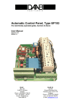
1
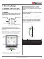
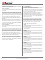
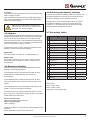
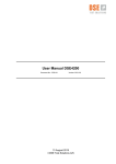
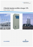
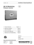
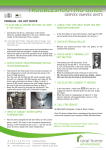
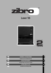
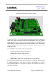
USER MANUAL
UK / Version 23.09.2014
OPTIMA 100 OPUS
OPTIMA 100 DESIGN
PCB ES951
Version 2012.02.28
GES ENERGY 1, GES ENERGY S/M, GE ENERGY 1/2/3
Genvex A/S • Sverigesvej 6 • DK-6100 Haderslev • Tel.: +45 73 53 27 00 • [email protected] • genvex.dk
Table of contents
Page
1. Mounting Design......................................................3
1.1 Installation of the control panel.................................3
1.2 Mounting...................................................................3
2. Mounting Opus.........................................................4
2.1 Installation of the control panel.................................4
2.2 Mounting...................................................................4
3. Operation..................................................................5
3.1 Use and changing of the settings.............................5
3.2 Ventilator Speed.......................................................5
3.3 Filter alarm...............................................................6
3.4 Bypass......................................................................7
3.5 Electrical Heating.....................................................7
3.6 Restoring the factory settings...................................8
3.7 Set points’ table........................................................8
4. Function....................................................................8
4.1 Extra capacity...........................................................8
5. Maintenance..............................................................9
5.1 Parts.........................................................................9
5.2 Alarms......................................................................9
5.3 Demounting / taking the system out of operation.....9
6. Troubleshooting.....................................................10
6.1 System does not operate.......................................10
6.2 Fault on the air side................................................10
7. Electrical Diagram..................................................11
2
Subject to technical modifications of Optima 100
1. Mounting Design
1.1 Installation of the control panel
The control panel is designed to be mounted onto a flat
wall.
1.2 Mounting
Find the location on the wall where you will fix the control
panel and mark the screw-hole positions. A min. of four
screws must be used, the two bottommost and the two
topmost.
Mandatory Screw
Mandatory Screw
Screw
Screw
Mandatory Screw
A low-current cable 8 x 0.25 mm2 must be attached
between the unit and the control panel. 10 m is the
maximum cable length. The voltage drop for cable
lengths over 10 m is too high and can result in unreliable
operation.
How to mount the wall fixture:
First screw the fixture securely onto the flat wall and pass
the cable up from below.
Connect the low-current cable to the terminal block. Check
that the cable is connected to the same numbers at both
ends. (Between the control panel and the main circuit
board in the unit.)
Next clip the control panel to the wall fixture by guiding
it down from above, slightly slanting out at the bottom.
Finish by pressing in at the bottom so that it sits flat
against the wall. For demounting: pull the control panel a
little out at the bottom and lift up.
Mandatory Screw
Hold the wall frame against the wall and mark the
screw-hole positions. Drilling of holes, hole size and the
corresponding screws for fixing the panel depend on the
wall material.
Place the control panel in the fixtures and tilt it in against
the wall. The four support points in the corner of the
display must touch the wall to keep the display stable.
Support
Point
Support
Point
Support
Point
Support
Point
Pos.
Description
1
Panel housing
2
Front of panel
3
Pressure plate for display
4
Wall fixture
5
Glass for the display
A
Underneath the control panel there is an access for the:
A: Terminal block. Connection to main circuit board
Subject to technical modifications of Optima 100
3
2. Mounting Opus
3. Operation
2.1 Installation of the control panel
All Genvex GE/S Energy and GEU residential ventilation
units can be operated with the Optima 100 control.
The control panel is designed to be fitted in the opening of
an Opus type plug socket.
The Optima 100 control has the following settings:
Ventilator speed, filter alarm, bypass ON/OFF and
electrical heating ON/OFF.
The control unit is supplied with factory set settings that
enable the unit to be operated without initially having to
change the settings. The factory settings are only basic
settings, which can be changed to suit the operational
requirements and needs of the building, so that the system
can be optimally used and operated.
3.1 Use and changing of the settings
2.2 Mounting
Find the location where the control panel is to be placed
and connect the lead first then click the control panel in
place.
Optima 100 Design is operated via the B3, B4 and B5
buttons. Optima 100 Opus is operated via the B3 and B5
buttons. With Opus the B4 button enables the B3 and
B5 buttons to be held down at the same time. The button
combinations that need to be used to change the ventilator
speed, reset the filter alarm and switch on/off the bypass
and/or electrical heating are described below.
A low-current cable 8 x 0.25 mm2 must be attached
between the unit and the control panel. 50 m is the
maximum cable length. The voltage drop for cable
lengths over 50 m is too high and can result in unreliable
operation.
Check that the cable is connected to the same numbers at
both ends. (Between the control panel and the main circuit
board in the unit.)
The button to the left of the control panel is B3 and the
button on the right is B5. B4, which we know from the
Design control panel is, in the case of Opus, just used to
hold both buttons down, i.e. B3 and B5 together.
1
B3
4
Subject to technical modifications of Optima 100
2
3
4
B4
B5
3.2 Ventilator Speed
Both ventilators can be set independently of each other,
so that the airflow at the inlet and outlet are equal, which
results in optimal operation. Commissioning of the unit
must be carried out using technical equipment for and
may be done without the use of a main regulating damper.
It is not advised to set the airflow without expert help and
guidance. Incorrect settings can result in increased energy
use.
You must manually select the ventilation unit’s operating
level. You can select this with a short press of the button
B3.
Choose the ventilation speed:
Level 0 inlet/outlet airflow: LEDs off –
Standby – cannot be set via the display
Level 2 outlet airflow
Level 2 is the recommended operating level for an optimal
indoor climate and should be commissioned to meet the
building’s ventilation requirements.
To access level 2 from the main display, hold down button
B3 for more than 10 seconds until LED D1 begins to flash.
Press button B4 once more until LED D2 begins flashing.
Outlet airflow can now be set to level 2.
If you are already in the ventilator settings menu, just
press B4 repeatedly until LED D2 begins flashing.
Each press of B3 decreases the level 2 outlet airflow by
1%.
Each press of B5 increases the level 2 outlet airflow by
1%.
To return to the main display, press button B4 repeatedly
until all of the LED’s stop flashing.
Level 1 inlet/outlet airflow: LED D1 on –
Default 25% (can be changed, see below)
Level 3 outlet airflow
Level 3 is the highest speed that can be set. It is typically
used when there are a lot of people, or there is a lot of
activity in the kitchen.
Level 2 inlet/outlet airflow: LED D2 on –
Default 50% (can be changed, see below)
Level 3 inlet/outlet airflow: LED D3 on –
Default 75% (can be changed, see below)
Level 4 inlet/outlet airflow: LED D4 on –
Always operated at 100% and cannot be set
By default the system is always operating. If the unit is to
be set to Standby, it can only be done via a data logger.
Alternatively, the unit can be switched off at the main
switch.
The procedure for setting the ventilator speed to level
1, 2 and 3 is described below. If no button is activated
within 100 seconds in the set-up menu, the control system
automatically returns to the main display.
Level 1 outlet airflow
Level 1 is the lowest speed. This is often used with no-one
is at home.
To access level 1 from the main display, hold down button
B3 for more than 10 seconds until LED D1 begins to flash.
Outlet airflow can now be set to level 1.
If you are already in the ventilator settings menu, just
press B4 repeatedly until LED D1 begins flashing.
Each press of B3 decreases the outlet airflow by 1%.
Each press of B5 increases the outlet airflow by 1%.
To return to the main display, press button B4 repeatedly
until all of the LED’s stop flashing.
To access level 3 from the main display, hold down button
B3 for more than 10 seconds until LED D1 begins to flash.
Press button B4 twice more until LED D3 begins flashing.
Outlet airflow can now be set to level 3.
If you are already in the ventilator settings, just press B4
repeatedly until LED D3 begins flashing.
Each press of B3 decreases the level 3 outlet airflow by
1%.
Each press of B5 increases the level 3 outlet airflow by
1%.
To return to the main display, press button B4 repeatedly
until all of the LED’s stop flashing.
Sucking out
Level 1 inlet airflow
Level 1 inlet airflow is to be adjusted to match the level 1
outlet airflow.
To access level 1 from the main display, hold down button
B3 for more than 10 seconds until LED D1 begins to flash.
Press button B4 three times more until LED D1/D5 begin
to flash at the same time. Inlet airflow can now be set to
level 1.
If you are already in the ventilator settings menu, just
press B4 repeatedly until LED D1/D5 begin flashing at the
same time.
Each press of B3 decreases the inlet airflow by 1%.
Each press of B5 increases the inlet airflow by 1%.
Subject to technical modifications of Optima 100
5
To return to the main display, press button B4 repeatedly
until all of the LED’s stop flashing.
Level 2 inlet airflow
Level 2 inlet airflow is to be adjusted to match the level 2
outlet airflow.
To access level 2 from the main display, hold down button
B3 for more than 10 seconds until LED D1 begins to flash.
Press button B4 four times more until LED D2/D5 begin to
flash at the same time. Inlet airflow can now be set to level
2.
If you are already in the ventilator settings menu, just
press B4 repeatedly until LED D2/D5 begin flashing at the
same time.
Each press of B3 decreases the level 2 inlet airflow by 1%.
Each press of B5 increases the level 2 inlet airflow by 1%.
To return to the main display, press button B4 repeatedly
until all of the LED’s stop flashing.
Level 3 inlet airflow
Level 3 inlet airflow is to be adjusted to match the level 3
outlet airflow.
To access level 3 from the main display, hold down button
B3 for more than 10 seconds until LED D1 begins to flash.
Press button B4 five times more until LED D3/D5 begin to
flash at the same time. Inlet airflow can now be set to level
3.
If you are already in the ventilator settings menu, just
press B4 repeatedly until LED D3/D5 begin flashing at the
same time. Inlet airflow can now be set to level 3.
Each press of B3 decreases the level 3 inlet airflow by 1%.
Each press of B5 increases the level 3 inlet airflow by 1%.
To return to the main display, press button B4 repeatedly
until all of the LED’s stop flashing.
3.3 Filteralarm
A built-in filter timer measures the amount of time the unit
has operated since the last filter replacement.
The filter timer can be set between 1-6, which corresponds
with 1-6 months. It is recommended to initially set the filter
timer to 3, corresponding to 3 months.
If the filters become too dirty during the set period, you
can set the filter timer to a lower number of months.
On the other hand, if the filters do not require replacement
at the end of the set period, you can set the filter timer to a
higher number of months.
When the filter timer reaches the set period for a filter
change, the LED of the current step will begin to flash.
When the filters have been changed, the alarm is reset
by holding button K4 down for more than 10 seconds. All
LEDs will briefly flash. Then the filter alarm is reset.
The filter timer is set as described below.
1 month
Hold the button B4 down for more than 10 seconds, until
LED D1 begins to flash.
Then press button B4 to confirm the setting and to return
to the main display.
2 months
Hold the button B4 down for more than 10 seconds, until
LED D1 begins to flash.
Then press button B5 once until LED D2 begins to flash.
Then press button B4 to confirm the setting and to return
to the main display.
3 months
Hold the button B4 down for more than 10 seconds, until
LED D1 begins to flash.
Then press button B5 twice until LED D3 begins to flash.
Then press button B4 to confirm the setting and to return
to the main display.
4 months
Hold the button B4 down for more than 10 seconds, until
LED D1 begins to flash.
Then press button B5 three times until LED D4 begins to
flash. Then press button B4 to confirm the setting and to
return to the main display.
5 months
Hold the button B4 down for more than 10 seconds, until
LED D1 begins to flash.
Then press button B5 four times until LED D1/D5 begin to
flash. Then press button B4 to confirm the setting and to
return to the main display.
6
Subject to technical modifications of Optima 100
6 months
Hold the button B4 down for more than 10 seconds, until
LED D1 begins to flash.
Then press button B5 five times until LED D2/D5 begin to
flash. Then press button B4 to confirm the setting and to
return to the main display.
NB: If there is a filter alarm, the filter timer
cannot be set. The filter timer must be reset
first, before, it can be set again.
3.6 Restoring the factory settings
If the set points that are installed result in the system not
operating as expected, and the cause cannot be found,
the factory settings can be restored as follows:
During start-up of the system hold B4 down so that all
five LEDs are flashing. As soon as all five LEDs stay
constantly on, the button B4 can be released, and the
system’s factory settings are restored.
3.7 Set points´ table
3.4. Bypass
Systems that are supplied with a bypass can operate in a
so-called summertime mode. The outlet air is let outside
the heat recovery circuit in the unit via a valve, so that
there is no heat recovery. The temperature of the air that
is let into the house is, thus, not heated, but corresponds
with the temperature of the air outside.
Text:
Factory
settings:
1
Inlet airflow rate 1 (0-100%)
25
2
Inlet airflow rate 2 (0-100%)
50
3
Inlet airflow rate 3 (0-100%)
75
4
Outlet airflow rate 1 (0-100%)
25
5
Outlet airflow rate 2 (0-100%)
50
6
Outlet airflow rate 3 (0-100%)
75
7
System Stop
OFF
8
Timer level 4
OFF
9
Timer level 4
3
10
Filter change
3
11
Filter stop
OFF
Electrical heating can either be accomplished by a preheating or post-heating element.
12
Frost protection
ON
14
Frost protection
1
A pre-heating element ensures that the heat recovery
circuit does not freeze with very low outdoor air
temperatures.
15
Extra heating
OFF
16
Extra heating
0
17
Menu On
The bypass function must be manually activated via the
display. This is done as per the following:
Bypass ON:
Do a short press on button B5, so LED D5 stays on.
Bypass OFF:
If LED D5 is constantly on, do a short press on button
B5 until D5 turns off. Bypass is OFF, if LED D5 is not
constantly on.
3.5 Electrical Heating
A post-heating element further heats the inlet air after
it has been heated via the heat recovery process in the
system.
The heating element must be activated manually via the
display. This is done as per the following:
Installed
settings
ON
Hard-coded:
Level 4 inlet, 100%
Level 4 outlet, 100%
Hygrostat, as per Optima 250.
To activate the menu, hold the button B5 down for more
than 10 seconds, until LED D1 begins to flash or the LEDs
D1/D2 flash at the same time.
Electrical heating ON:
LEDs D1/D2 flash at the same time
Electrical heating OFF:
LED D1 flashes
Press button B5 for a short period to change between ON
and OFF.
Press button B4 to return to the main menu.
Subject to technical modifications of Optima 100
7
4. Function
G4 = Standard Filter (Coarse filter class G4)
F5 = Fine Filter (Fine filter class F5)
F7 = Pollen Filter (Fine filter class F7)
4.1 Extra capacity
Electrical heating:
Bypass is controlled manually by button B5.
Bypass:
Bypass is controlled manually by button B3.
5. Maintenance
For any system controlled by Optima 100, e.g. the Energy
range, you must check if LED D5 is constantly lit or if it
flashes. If it flashes, it means that the filters in the unit
must be changed.
For optimal operation, please observe the following points:
Before opening the unit, turn off the power/
unplug the unit and wait until the ventilators
are completely still.
Ventilators:
Remember to turn off the power before inspecting the
unit!!
The fan impellers in the ventilator should be checked for
dirt and contaminants every year.
Demount the front cover on the unit. Clean the ventilators
with a scrubbing brush, bottle brush or duster. NB. Do not
remove the balancing weights on the ventilator impellers
otherwise this will cause imbalance and result in noisy
operation and wear of the ventilators.
After the unit has been installed and operating for a couple
of days, it should be checked if the condensation outlet is
functioning.
Inlet and outlet air valves:
The valves are to be cleaned using a dry cloth. Ensure
that the valve does not rotate as this will alter the airflow.
Environmental requirements:
If icing occurs or if the unit is to be demounted, the
relevant environmental requirements must be followed
in association with recycling and disposal of the various
materials according to the regulatory requirements.
Service:
If you are unable to maintain/service your system, you
can make a service agreement with the Genvex service
department. If there is a fault with the system, please
contact the Genvex service department.
5.1 Parts
Filters:
When LED D5 for the filters in the display is flashing on
the control panel, the filters need to be replaced.
The unit is stopped via the main switch for the system or
via the data-logger. The filters are replaced and the filter
timer is reset. If desired, change the filter-replace time
period in the menu.
It is not recommended to vacuum or use
air pressure on the filter, as these will
compromise the filtering capability.
Cutting hazard: The fins have sharp edges.
The fins must not be damaged.
8
Condensate and condensation outlet:
The condensation outlet must be checked for blockages
and the water trap must be checked for water in
association with changing filters before autumn begins.
Pour 1 liter of water in the condensation water tray and
see if the water drains freely. If the condensation outlet
does not work, there is a risk of water damage in the
building.
5.2 Alarms
Filter timer:
The control system has a filter timer to ensure the filters
are replaced regularly and the unit operates optimally. At
the time when the filter reaches the set value, LED D5 will
begin to flash in the display until the filters are changed.
5.3 Demounting / taking the system
out of operation
The following is to be done:
The power must be disconnected from the unit, i.e. the
electrical cable is disconnected. Take out the condensation
outlet and electrical cables for any pre or post heating.
Disconnect leads to the panel and dismantle ducts.
If the unit is to be taken out of operation, the ducts must
be dismantled to prevent condensation in the system and
in the ducts. Close all inlet and outlet air valves.
Subject to technical modifications of Optima 100
6. Troubleshooting
6.1 System does not operate
System stopped:
No light in the display panel even when the button is
pushed.
Fault:
• The fuse in the panel has blown – no power to unit.
• One of the fuses on the circuit board has blown.
• Loose cable, no power to the unit.
• Loose cable between the unit and the operating
panel.
• “Filter fault” on the unit.
Condensate runs out of the unit:
Fault:
• Condensation outlet blocked with dirt and
contaminants.
• No water in water trap.
• No condensation on the ground due to frost.
• The outlet is not sufficiently protected against frost.
6.2 Fault on the air side
No inlet air to residence’s rooms.
Fault:
• Defective ventilator.
• Blocked filter.
• Dirt and leaves in the fresh air vent in Autumn or
snow and ice in Winter.
• Control circuit fuse has blown.
No outlet air from wet rooms.
Fault:
• Defective ventilator.
• Blocked filter.
• Exhaust vent / roof cap is blocked with ice and snow
in the Winter.
Cold inlet air:
Fault:
• The counter flow heat exchanger is blocked with dirt
or ice.
• The extract air ventilator is defective.
• The exhaust air filter is blocked.
If the fault is not stated above, please contact the person
who installed the system or the GENVEX customer
centre.
Subject to technical modifications of Optima 100
9
ES951
L2
1
2
1
2
3
4
1
2
3
4
5
6
7
8
1
2
3
4
5
1
2
3
4
5
6
7
8
H1
1
Q1=1,6A
L1
PE
7. Electrical Diagram
L3
2
H3
1
2
1
2
1
2
L4
L6
R2
R4
H7
R1
H8
H9
1
2
3
PE
R3
1
N
PE
Blue
1
230V
H7
2
Brown
Red
Blue
M4
1
L6,1
M1
H8
2
+5V
GND
EC-Fan
Exhaust
Max 1,0A
2
1
L
PE
N
4
1
3
4
Electrical Heater/Preheater
Yellow
230V
3
K5
6
C4
7
C3
+5V
8
C1
90°C
manu
Yell/Green
1
K4
24
C2
L3
H3
2
K3
23
5
22
OPTIMA 100 DESIGN
230V
2
21
H1
PE
Sensor Heater/Preheater
T1
1
T9
L2
2
Sensor Exhaust air
3
T4
PE
L1
Mains
1x230VAC, 50Hz
MAX Fuse 10A
Must be connected
to earth
2
L1
2
1
2
3
1
Genvex
Hygrostat
Potentialfree
Contact
Must be used
Yellow
EC-Fan
Supply
Max 1,0A
10
M2
Blue
L6,2
7
Blue
6
5
M1
8
EC-Fan
Exhaust
Max 1,0A
M2
Yellow
Subject to technical modifications of Optima 100
Brown
Blue
1
230V
H9
PE
EC-Fan
Supply
Max 1,0A
2
3
Yell/Green
4
Connection
for Dataloging
Our Units and Controls – Your Choice
Genvex has more than 40 years of experience in creating quality units
providing optimum indoor climate with excellent energy efficiency. Our
systems employ the newest technologies in heat recovery and have heat
recovery rates of up to 96%. The systems are continuously optimised with
the newest technologies.
Advanced controls ensure that as little energy as possible is used for
reaching an optimum level of comfort.
Today’s and future construction place greater and greater requirements
for energy-friendly, yet compact systems. We at Genvex are aware of this
and are continuously developing solutions that meet these needs. For
example, a brilliant solution for decentralised housing ventilation is a
range hood solution with full integration to the system’s control which
ensures that the most efficient ventilation system is achieved with the
simplest installation.
Genvex A/S • Sverigesvej 6 • DK-6100 Haderslev • Tel.: +45 73 53 27 00 • [email protected] • genvex.dk