1
Digital-Flexo-Cut
User Manual
English
Index
1 Safety Precautions.................................................................................................................................3
2 Proper Use ............................................................................................................................................4
3 Description and Specifications ...............................................................................................................4
4 Accessories ...........................................................................................................................................5
5 Start-Up: ................................................................................................................................................7
6 Controls: ................................................................................................................................................7
7 Mounting a New Cutting Plate: ...............................................................................................................8
8 Register Adjustment in Longitudinal Direction:........................................................................................8
9 Correcting the Lateral Offset: .................................................................................................................9
10
Correcting the Angular Offset: ..........................................................................................................9
11
Possible Sources of Failures: .........................................................................................................10
12
Further Options of Adjustment on the Display: ................................................................................11
12.1
Basic Settings ............................................................................................................................11
12.2
Fine Tuning................................................................................................................................12
13
Service Mode: ................................................................................................................................13
13.1
First Service Menu: ....................................................................................................................13
13.2
Second Service Menu: ...............................................................................................................14
13.3
Third Service Menu: ...................................................................................................................15
14
Operating Instructions Feeder ........................................................................................................16
14.1
Safety Instructions......................................................................................................................16
14.2
Description.................................................................................................................................16
14.3
Installation..................................................................................................................................16
15
Feeder Adjustments .......................................................................................................................17
15.1
Paper Size Adjustment...............................................................................................................17
15.2
Infeed Angle...............................................................................................................................17
15.3
Suction Drum and Paper Gate....................................................................................................17
15.4
Compressed Air and Vacuum.....................................................................................................18
16
Technical Specifications of the Feeder ...........................................................................................18
17
Trouble Shooting............................................................................................................................18
18
Ordering Cutting Plates ..................................................................................................................19
DECLARATION OF CONFORMITY ............................................................................................................20
19
Glossary / Abbreviations.................................................................................................................21
20
Ammendment Index .......................................................................................................................21
© Ernst Nagel GmbH
9965197 User Manual IA DFC.doc
Rev.1.4 3/9/09
Pg.2
1
Safety Precautions
1. Please read this instruction and the Wink ABC (cylinder) carefully and completely before operating
the machine. Attention, deviating from the ABC, the DFC has a gap clearance of 0.8 mm.
2. Please make sure the mains voltage is suitable and the outlet has a proper earth connection.
3. Use an exclusive outlet, as overloading may cause fire or an electric shock.
4. Do not unplug the plug or unplug the power cord from the outlet with a wet hand , this can cause an electric shock or injury.
5. Repairs have to be carried out by trained Nagel technicians only.
6. Disconnect the machine from the mains while servicing it.
7. Use original Nagel consumables and spare parts only.
8. Lay the cables in a way that no dangers arise.
9. Install the machine in a dry room on levelled and solid ground. And within easy reach.
10. Block the breaks after putting the machines in place.
11. Safety precautions like covers or switches must not be removed or bypassed.
12. Always replace fuses with the same type and rating.
13. Users with long hair need to keep safe distance to turning parts.
14. Close lids that they don’t fall.
15. Don’t open lid during operation this could cause paper jams.
16. Connect the machines with the provided screws. It is not allowed that they can be disconnected w/o
tools.
17. Allow at least 20 seconds to pass between attempts to switch on the unit, otherwise the software may be
damaged.
18. When changing plug connections, always switch off the machines!
19. Work careful at the leaf springs. They consist of thin sheet metal and could cause injury through incautious contact.
20. Do not place receptacles containing liquids on any surface.
21. Do not under any circumstances adjust the paper gate, or other parts when the machine is switched on.
Attention! Important for startup:
If the DFC is connected to left turning three phase current, the pump will generate
an uncomfortable noise. This condition is harmful to the pump. Therefore power off
the machine immediately and swap two of the three phases.
Attention! Important for operation:
Please do not over tighten the tensioning bolts, which apply the cutting pressure.
This will shorten the lifetime of the plain rollers, see WINK „The ABC of cutting
tools“.
© Ernst Nagel GmbH
9965197 User Manual IA DFC.doc
Rev.1.4 3/9/09
Pg.3
2
Proper Use
Proper use consists in die-cutting, kiss-cutting and perforating paper, cardboard, labels and foils. The maximum thickness must be observed – it is determined by the gap between the cylinders and by the plate
thickness.
3
Description and Specifications
Production speed: Up to 2000 cutting strokes /h
Maximum format: 500 mm x 350 mm (L x W)
Minimum format: 90 mm x 160 mm (L x W)
Cutting cylinder perimeter: 20 inches (508 mm)
Cutting plate thickness: max. 0.80 mm (for die-cutting), this equals the gap clearance between the cylinders
Power connection: 3 x 400 volts / 16 A
© Ernst Nagel GmbH
9965197 User Manual IA DFC.doc
Rev.1.4 3/9/09
Pg.4
4
Accessories
Outlay table (3955070) – a cost-efficient alternative to complex outlay systems
Convey (3955061)
Fan wheel (3955066)
© Ernst Nagel GmbH
9965197 User Manual IA DFC.doc
Rev.1.4 3/9/09
Pg.5
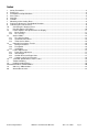
Installation of the Optional “fan wheel 3955066“
Fasten plate 3955048 for the cover to the front plate of the DFC using 2 DIN 912 M6x12 screws.
Remove two screws (see above) and use them to mount the delivery wheel in holes 3 and 5.
Connect the power cable for the motor and the encoder.
Fit the table assembly 3955036 at the cross bar.
Fit the cover TBD assembly at the DFC.
Fit the feeder as shown.
The stripping angles 3955065 are fastened to the table with the glued-on magnetic plates.
© Ernst Nagel GmbH
9965197 User Manual IA DFC.doc
Rev.1.4 3/9/09
Pg.6
5
Start-Up:
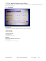
Turn on the machine at the main switch, to the left of the control panel. The “emergency stop button” must
not be actuated at this time. You will see the main menu.
Main menu
Press the button “Start Homing”. The magnetic cutting cylinder moves to its reference position (zero position)
– you will see a check mark once the process has been successfully completed. Important : In case of
using paper size bigger than A4, the “>A4” – button must be activated, otherwise the paper won’t be
ejected completely !
6
Controls:
Upper controls, from left to right:
“Start” button, “Rotation left” button, “Rotation right” button, rotary switch “Setup or Production”
Lower controls, from left to right:
“Stop” button, “Single sheet feed” button, rotary switch “Continuous feed on/off”, “Emergency stop”
© Ernst Nagel GmbH
9965197 User Manual IA DFC.doc
Rev.1.4 3/9/09
Pg.7
7
Mounting a New Cutting Plate:
Rotary switch “Setup or Production” on the upper right to Jog.
Use the “Rotation left” or “Rotation right” button to adjust the magnetic cylinder until both stop pins are at the
top. Place the cutting plate onto the middle of the cylinder; pay attention to the marking in the centre of the
plate.
Draw in the plate with the “Rotation left” button.
Set the rotary switch “Setup or Production” on the upper right back to “Reg”. The DFC cutter moves back to
reference position.
Adjust the lateral stops of the feeder so that the sheet to be fed is centred.
Adjust the lateral stop of the oblique belt.
Set the rotary switch “Continuous feed on/off” on the lower right to zero.
Press the “Start” button on the upper left.
The blower is started and the belts are set in motion.
Adjust the blast air so that the sheets in the stack are well separated.
Press the button “Single sheet feed” to feed a sheet into the machine.
Press the “Stop” button on the lower left.
8
Register Adjustment in Longitudinal Direction:
Measure the offset in longitudinal direction with a ruler. Press the “Enter” button on the display, to the right of
the “Reset Register” button. You will see an input box in which you can enter the measured value. Repeat
these steps, if necessary.
Should the cutting-contour be moved into the opposite direction of the direction of transport, a negativ value
must be entered.
© Ernst Nagel GmbH
9965197 User Manual IA DFC.doc
Rev.1.4 3/9/09
Pg.8
9
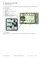
Correcting the Lateral Offset:
Names of the items:
Locking screw of the lateral guide (LL)
Micro adjusting screw of the lateral guiding (ML)
Guiding block
Locking screw for fine adjustment (LF)
Ball cage out of plastic material
To correct a larger deviation, loosen LF and LL, then
move the lateral guiding along the guiding block to your
desired position. Fasten LL again.
For fine adjustment fasten LF, loosen LL and use ML to
move the lateral guiding in the desired direction.
Fasten LL again.
10 Correcting the Angular Offset:
An angular deviation can be corrected by the thumb wheel as shown in the pictures above. Please notice
that the paper stop is always orthogonal to these cylinders. If very thin and flexible paper is used, rather the
cutting plate should be repositioned.
© Ernst Nagel GmbH
9965197 User Manual IA DFC.doc
Rev.1.4 3/9/09
Pg.9
Attention:
Inprecisions in this place can also result from the used balls and their weight.
Here are two examples following:
Light papers, heavy balls
By using too heavy balls for light papers, the paper sheet might be pulled with too much force against the
lateral guiding and a bulge appears between the balls and the lateral guiding. If the distance between the ball
bar and the lateral guiding ist too big, a similar effect apears.
Heavy papers, light balls
By using too light balls for heavy papers, it might happen, that the paper sheet isn’t pulled to the lateral
guiding. In this case the paper sheet isn’t aligned properly and runs random between the rotation cylinders.
Production:
Turn rotary switch "JOG/ REG" to REG
Now the cylinder turns to the home position (a check mark behind the array "Start Homing" should appear)
Otherwise touch the array "Start Homing", so that the cylinder turns into home position.
Turn rotary switch "continious feed" to the right.
Push "Start".
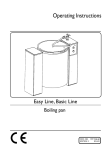
11 Possible Sources of Failures:
Cutting-/Creasing-/Perforating- Contour jumps:
Belt-speed too fast, residence time ("Timer Stopper") to short, balls too light.
By using thin waved material (e.g. because of humidity) it may happen that the leading edge goes up the
paper stop. In this case the material can be processed anyway, if a simple deflector (e.g. a stripe out of
paperboard) is beeing attached.
Paper jam:
The sheet stays stuck in the cutting-/ creasing-/ perforating- contour and is beeing deflected upwards, instead of beeing moved out straight. Stripes or plates out of natural rubber (3955081) should be attached
along the cutting-/ creasing-/ perforating- contour. The elastic material pushs the paper sheet away from the
cutting plate on the cylinder and enables an uncomplicated transport.
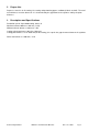
Cutting-/Creasing-/Perforating- Contour is in delay:
The paper sheet "swims" in the gap between the cylinders. By attaching a stripe out of natural rubber
(3955081) at the perimeter of one of the two cylinders the sheet will be transported in a secure way, see
picture below.
plexiglas
deflector
paper stop
belt
© Ernst Nagel GmbH
9965197 User Manual IA DFC.doc
Rev.1.4 3/9/09
Pg.10
12 Further Options of Adjustment on the Display:
You can navigate to the next screen, or to the previous screen, by means of the “Arrow right” and “Arrow left”
buttons of the touch panel.
12.1 Basic Settings
"Counter on/off"
The continuous feeding mode will not work while the counter is deactivated.
"Sheets per Pack":
"Number of Packs":
"Rotations per Pack":
"Reset Counter":
Resets the counter to zero
Arrow left:
Takes the operator back to the main menu
Arrow right:
Takes the operator to fine tuning menu
© Ernst Nagel GmbH
9965197 User Manual IA DFC.doc
Rev.1.4 3/9/09
Pg.11
12.2 Fine Tuning
"Triggertime":
Configures the time span of the opening of the vacuum valve at the suction drum of the feeder. If this
time span ist too short, the paper sheets will stay lying in the feeder. For working with big sheets the time
span should be a bit longer. If there is an appearance of doubled sheets, the time span should be chosen
shorter.
"Timer Stopper" (paper stop):
Waiting period during recognition of the front-edge of the sheet and the sinking of the paper stop (see also
p.8, Chapter 10). If the period is adjusted too short, the sheet might vibrate or doesn’t lie properly at the
paper stop by the time. On the other hand the sheet might be damaged by the bevel belt if the chosen period
is too long.
"Executiontime":
Runtime of the optional convey (3955061).
"Deliveryspeed":
Time period of 1/8 Turn of the optional delivery wheel in % of the maximum speed.
"Diecuttingspeed":
Speed of the cutting cylinder. It might be adjusted to a fast speed.
"Beltspeed":
Speed of feeder and bevel belt. It might be increased if using heavy stock.
© Ernst Nagel GmbH
9965197 User Manual IA DFC.doc
Rev.1.4 3/9/09
Pg.12
13 Service Mode:
To go to service mode, touch the “Nagel” symbol on the main menu. Then enter the password 4711. Press
Enter to return to the main menu. Then press “Nagel” again to go to the first service menu.
13.1 First Service Menu:
"Homingspeed":
Rotation speed of the cylinder during going into home position
"Jogspeed":
Rotation speed when turning the cylinder by buttons in "JOG"-mode
"Machineregister":
254 = half of the cylinders perimeter (don’t change)
"Registeradjustment high":
The value the register is altered by pushing the buttons for more than a second (during production).
"Registeradjustment low" (fine):
like "Registeradjustment high", accept the value is 0.1 mm
"Beginpunt Uitlegeband":
The distance the cutting cylinder turns in mm until the convey (3955061) begins to run
"Counter total":
Read only.
Important: Before the software is getting an update the value has to be written down, because after
the update the value will be zero again !
© Ernst Nagel GmbH
9965197 User Manual IA DFC.doc
Rev.1.4 3/9/09
Pg.13
13.2 Second Service Menu:
Start
RegFwd
RegBwd
Torn/Reg
Stop
TactSingle
TactAuto
Noodstop
Here the several sensors and the buttons of the user panel can be checked. An active sensor/ button causes
a check mark on the display as shown above.
ProductSenso:
The reflex lightbar which detects the front-edge of the sheet before reaching the paper stop
TactSingle:
Single sheet – button
Uitlegsensor:
Sensor of the (optional) delivery wheel 3955066
RegBwd:
"Rotate right" – button
TactAuto:
continious feed switch
Dubbelsheet:
Doublesheet – sensor (not implemented)
RegFwd:
"Rotate left" – button
Noodstop:
"Emergency Stop" – button
Safetyinput:
(not implemented)
Homingsensor:
Sensor Home position of the cutting cylinder
Start:
"Start" – button
Stop:
"Stop" – button
Torn/Reg (Jog/Reg)
"Setup or produce" – turning switch
© Ernst Nagel GmbH
9965197 User Manual IA DFC.doc
Rev.1.4 3/9/09
Pg.14
13.3 Third Service Menu:
In this menu, you can enter settings for various machine components and choose the display language.
Vacuumvalve:
230 Volt at valve (attached to pump)
Delivery:
230 Volt AC at extern jack for optional delivery wheel 3955066
Vacuumpump:
230 Volt at pump
Feeder:
230 Volt at motor of feeder
Paper stop:
230 Volt at solenoid of the paper stop
Uitlegeband:
24 Volt DC at extern Jack for convey (3955061).
© Ernst Nagel GmbH
9965197 User Manual IA DFC.doc
Rev.1.4 3/9/09
Pg.15
14 Operating Instructions Feeder
14.1 Safety Instructions
For safety reasons, always first unplug the main plug before undertaking any repair or maintenance work.
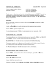
14.2 Description
1
2
3
4
5
6
7
8
9
Paper guides L and R
Back stop
adjustment screw for paper infeed
Air jets
Vacuum drum
Adjustment screw for suction slot
Paper gate
Height adjustment screw for paper gate
Set screw for gate position
6
2
3
1
4
9
8
7
1
5
14.3 Installation
By hooking the feeder to the catching bolts, the necessary connection to the drive is accomplished.
© Ernst Nagel GmbH
9965197 User Manual IA DFC.doc
Rev.1.4 3/9/09
Pg.16
15 Feeder Adjustments
15.1 Paper Size Adjustment
After the lateral paper guides (1) have been adjusted to the size of the paper being processed, the back stop
(2) has to be placed at the end of the paper pile. This avoids the paper moving backwards because of the air
blow. To achieve a maximum sheet separation, all air jets (4) outside the paper stack have to be closed (thus
ensuring optimal air pressure under the stack).
15.2 Infeed Angle
The paper infeed angle to the folding rollers can be adjusted by the adjustment screw (3).
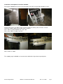
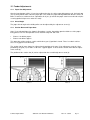
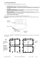
15.3 Suction Drum and Paper Gate
Gate (7) must be positioned as shown in illustrations 1 and 2, depending upon the thickness of the paper
being processed. The ideal position can be determined by trial and error:
•
•
Picture 1 for thicker papers
Picture 2 for thinner papers
This procedure might require 2-3 trials until the best gate (7) position is found. There is no basic rule because every paper feeds differently.
The suction slot (A) must always be adjusted to the position of the gate (7) by adjustment screw (6). After
positioning, the gate (7) has to be set to leave a gap of approx. 2 sheets to the suction drum with the adjustment screw (8).
The position of the suction slot (A) can be adjusted on the run with adjustment screw (6).
Picture 2
Picture 1
© Ernst Nagel GmbH
9965197 User Manual IA DFC.doc
Rev.1.4 3/9/09
Pg.17
15.4 Compressed Air and Vacuum
On most vacuum pumps the volume of air can be adjusted by means of valves provided for this purpose. If
less vacuum is required for very light papers, a reduction can be achieved by adjusting the air supply on the
pump directly.
Normally the air supply on the vacuum pump is set to the maximum.
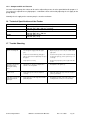
16 Technical Specifications of the Feeder
Minimum size
Maximum size
90 x 120 mm (standard)
235.201 (A3): 350 x 500 mm (standard)
245.201 (A2): 450 x 650 mm (standard)
Friction by the drive shaft of the folding machine
235.201 (A3): 387 x 700 mm
245.201 (A2): 487 x 700 mm
235.201 (A3): 9.7 kg
245.201 (A2): 14 kg
Drive
Dimensions
Weight
17 Trouble Shooting
Problem
Paper is not being fed.
Cause
Remedy
o
Not enough air supply under the paper
pile.
o
Open air jets (4) or close air jets outside of the
paper pile.
o
Position of vacuum drum (5) and paper
gate (7) has not been adjusted precisely to
the paper.
o
Search for the position of the vacuum drum (5)
to the paper gate (7) (refer to point 15.3.). Use
screw (9).
o
Paper pile is too heavy.
o
Reduce the paper pile, put less paper into the
feeder.
Paper piles up after the
paper gate, before
entering the folding
rollers.
o
Side guides (1) have been adjusted too
narrow or are not parallel.
o
Readjust the side guides (1).
Double sheets
o
Paper gate (7) has not been adjusted
correctly.
o
Adjust the paper gate (7) to 2 sheets of paper
(refer to point 15.3.).
Front edge of sheets are
being marked by the
paper gate
o
Paper gate (7) is in wrong position for this
particular paper.
o
Readjust the position of the paper gate (7) in
moving it back or forth). Use set screw (9).
© Ernst Nagel GmbH
9965197 User Manual IA DFC.doc
Rev.1.4 3/9/09
Pg.18
18 Ordering Cutting Plates
To order a cutting plate the following specifications are necessary:
•
•
•
•
•
•
•
The gap clearance of 0.8 mm (distance between the cylinders)
The thickness of the paper. The specification g/m2 won’t be enough, because it doesn’t necessarily
tell anything about the thickness. However this information is important for creasing, stamping and
kiss cutting.
The direction of transport, because the cutting plate has to be shortened in perimetric direction.
The position of the hold points at partial cutting
Position, orientation and reference of the drawing (e.g. topview or bottom view, referenced to
paper or cutting plate)
The perimeter is 508 mm, the maximum lenghth of the cutting plate is 504 mm (because of the
stop pins, which shouldn’t be covered by the plate)
The maximum breadth is 360 mm.
The drawing must be true to scale. Following scalable file-types may be used:
PDF, AI, EPS, DWG, DXF. More precisely informations are available from the specific manufacturer of the
cutting plates.
direction of
transport
printed surface
direction of
transport
A stamp, e.g. for folded boxes, is beeing done from the backside. This means, that in this case the material
lies face down.
direction of
transport of the
paper
ABC
ABC
paper
paper
perforated
the cutting is
done onto
printed surface, topview
onto printed
surface, scale
1:1, format
A4
measure
(e.g.120
mm)
cut
hold points
© Ernst Nagel GmbH
9965197 User Manual IA DFC.doc
Rev.1.4 3/9/09
Pg.19
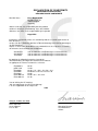
DECLARATION OF CONFORMITY
KONFORMITÄTSERKLÄRUNG
DÉCLARATION DE CONFORMITÉ
We/ Wir/ Nous:
Ernst Nagel GmbH
Breitwiesenstr. 21
70565 Stuttgart
Germany
declare under our sole responsibility that the product/
erklären in alleiniger Verantwortung, dass das Produkt/
déclarons sous notre seule responsabilité que le produit
Nagel DFC
to which this declaration relates is in conformity with the essential requirements of
EEC directives/
auf das sich diese Erklärung bezieht, in Übereinstimmung ist mit den Bestimmungen
der EU Richtlinien/
auquel se réfère cette déclaration est en conformité avec les exigences essentielles
des directives de la communauté européenne
89/336/EEC
89/392/EEC
73/23/EEC
and amendments/ und Änderungen/ et amendements
and amendments/ und Änderungen/ et amendements
and amendments/ und Änderungen/ et amendements
by applying the following harmonized standards/
unter Anwendung der folgenden harmonisierten Normen/
en appliquant les normes harmonisées suivantes
EN 60204-1
prEN 1010
EN 60950
EN 55022
EN 55024
EN 61000-3-2
EN 61000-3-3
06.93
10.99
08.92, + A1 + A2 + A3 + A4 + A11
09.98 Klasse B/ class B/ classe B
09.98
04.95 + A1 + A2 + A14
01.95
Year of affixing the CE marking/
Jahr der Anbringung der CE-Kennzeichnung/
L' an de l' application de la marque CE:
2008
Stuttgart, October/ 02/ 2008
Place and Date/
Ort und Datum/
Lieu et date
Managing Director/
Geschäftsführer/
Gérant
19 Glossary / Abbreviations
BG = assembly (Baugruppe)
ELR = Electron. Load-Relais
GND = Ground
H x W x D = Height x Width x Depth
IR = Infra red
RH = Relative humidity
20 Ammendment Index
Rev. 1.0
Rev. 1.3 Service Screens, Trouble shooting DFC, Instructions Feeder
Rev. 1.4 Ordering Information
© Ernst Nagel GmbH
9965197 User Manual IA DFC.doc
Rev.1.4 3/9/09
Pg.21
Ernst Nagel GmbH
D - 70565 Stuttgart, Germany
Inland
0711-78078 11
Export +49 711-78078 21
Telefax +49 711-78078 10
www.ernstnagel.com