1
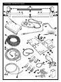
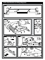
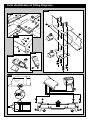
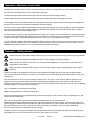
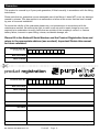
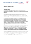
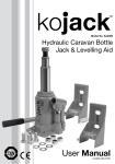
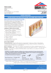
Enduro Caravan Mover
Model Number: EM103
User Manual
Ref: EM103-UM-0808-A4-Rev.F.
Package Contents (Fig.A)
5
4
2
1
3
31
32
6
16
11
33
7
9
10
12
13
27
17
18
8
20
21
29
28
23
19
22
14
1
2
24
1
25
2
2
2
3
1
1
3
3
4
15
26
-
+ +
-
-
-
+
3
4
+
4
4
30
Parts Identification & Fitting Diagrams
Fig.1
A
B
C
Fig.4
Fig.5
B
B
H
C
F
A
D
E
Fig.8
Fig.10
30mm
A
B
A
Fig.9
Fig.11
A
✗
✓✗
E
D
G
F
A
C
Parts Identification & Fitting Diagrams
Fig.2
Fig.6
A
A
A
A
Fig.3
D
C
B
A
Fig.7
Fig.7.1
A
Fig.12
-
1
2
+
-
+
Caravan
Front
B
A
3
4
+
-
Parts Identification & Fitting Diagrams
Fig.13
Fig.14
185mm
(min)
2.8mm to 3.5mm
165mm
(min)
30mm to 45mm
85mm (min)
1800mm to 2400mm (max)
I Table of Contents
Package Contents (Parts List)
Page 1
Introduction
Page 2
Intended Use
Page 2
Specifications
Page 2
Installation Safety Guidelines
Page 2,3
Installation - Mechanical Components
Page 3,4
Installation - Electrical/Electronic Components
Page 4,5
Operation Safety Guidelines
Page 5,6
Operation - Motor Units
Page 6
Operation - Remote Control Handset
Page 6,7
Operation - Electronic Control Unit
Page 7
Operation - Getting Started
Page 7,8
Operation - Hitching and Unhitching
Page 8
Maintenance
Page 8
Trouble-Shooting
Page 8,9
Package Contents (Fig.A)
Ref
Qty
Description
Ref
Qty
1
1
Motor Unit (A)
18
8
Chassis Clamp Washers 10mmØ
2
1
Motor Unit (B)
19
20
P-Clip Screws - M4x15
3
1
Main Cross Bar
20
10
Cable Trunking P-Clips 19.2mm
4
1
Cross Actuation Centre Bar
21
10
Cable P-Clips 10.4mm
5
2
Cross Actuation Insert Bars
22
4
Battery Terminal Connector 8mmØ
6
1
Engagement Tool
23
2
Battery Terminal Connector 6mmØ
7
4
Chassis Stop Blocks
24
6
Cable Spade Connectors
8
2
Upper Chassis Clamp Plate
25
3
Cable Number Markers (1,2,3,4)
9
2
Chassis U Plate
26
3
Cable Polarity Markers (+,-)
10
2
Lower Chassis Clamp Plate
27
4
Motor Unit Cable Ties 8x400
11
1
Convoluted Cable Trunking
28
10
Cable Ties 2x70
12
2
Positive (+) Red Motor Cable 5m
29
1
Battery Isolation Switch, Cover & Key
13
2
Negative (-) Black Motor Cable 5m
30
2
Roller Distance Spacers 30x30
14
1
Positive (+) Red Battery Cable 1.8m
31
1
Remote Control Handset with Lanyard
15
1
Negative (-) Black Battery Cable 1.6m
32
1
Electronic Control Unit
16
8
Chassis Clamp Bolts - M10x40
33
1
Instruction Manual
17
8
Chassis Clamp Nylock Nuts M10
Enduro®
Page 1
Description
Ref: EM103-UM-0808-Rev.F UK.
Introduction
Congratulations on choosing the Enduro® Caravan mover. This has been produced according to very high standards
and has undergone careful quality control procedures.
Simply by using the remote control you can move your caravan effortlessly into any position required within operating
guidelines.
Before proceeding with installation and starting to use the mover, please read this manual very carefully and be aware of
all the safety instructions! The owner of the caravan will always be responsible for correct use. Keep this manual inside
your caravan for future reference.
The caravan mover consists of two 12V motor-power rollers, a 12V electronic control box and a remote control. To
function, the motor-powered rollers must be engaged against the tyres of your caravan. The supplied cross actuation
device enables you to engage both rollers at the same time from one side of your caravan. Once this is done the mover
is ready for operation. The remote control will allow you to move your caravan in any direction. You can even rotate the
caravan on it’s own axis, without moving forwards or backwards.
Intended Use
The Enduro® EM103 Caravan mover is only suitable for single axle caravans.
Suitable only for L-profiled chassis with a chassis thickness between min. 2.8mm and max. 3.5mm.
The standard installation kit only provides parts for installing the mover within the measurements given in Fig.14.
Specifications
Designation
Specifications
Enduro® Mover EM103
Operational Voltage
12 Volt DC
Average Current Consumption
40 Ampere
Maximum Current Consumption
120 Ampere
Speed
20cm per sec.
Weight
approx. 35Kg (exclusive of battery)
Permissible Overall Weight
1800Kg
Permissible Overall Weight on 20% Gradient
1450Kg
Minimum Width (caravan/trailer)
1800mm
Maximum Width (caravan/trailer)
2400mm
Maximum Tyre Width
205mm
Power Source (caravan leisure battery)
12V 105Ah (recommended), 12V 85Ah (minimum)
Installation Safety Guidelines
Important Safety Instructions
Read this User Manual carefully before installation and use. Failure to comply with
these rules could result in serious injury or damage to property.
These symbols identifiy important safety precautions. They mean CAUTION! WARNING!
SAFETY FIRST! IMPORTANT INFORMATION!
Ref: EM103-UM-0808-Rev.F UK.
Enduro®
Page 2
Before starting installation under the caravan:
DO check that the caravan is disconnected from the battery supply and the mains electrical supply.
DO only use adapters and accessories that are supplied or recommended by the manufacturer.
DO check that the tyres are not over worn (fitting to new or nearly new tyres is the best option).
DO make sure that the tyre-pressures are correct to the manufacturer’s recommendation.
DO make sure the chassis is in good condition without any damage and is free from rust, dirt etc.
DO stop work immediately if you are in doubt about the assembly or any procedures and consult one of our engineers
(Please refer to contact information on the last page of this manual).
DO locate the battery isolation switch to be accessible at all times when parking and moving the caravan.
DO NOT remove, change or alter any parts of the chassis, axle, suspension or brake mechanism.
DO NOT operate the unit if you are under the influence of drugs, alcohol or medication that could impair your ability to
use the equipment safely.
Installation - Mechanical Components
These instructions are for general guidance. Installation procedures may vary depending
on caravan type.
Working under a vehicle without appropriate support is extremely dangerous.
Please refer to Fig.13 for an overview of the whole assembly fully fitted.
Place the caravan on a hard, level surface. The use of a lifting ramp or an assembly pit is ideal for access and personal
safety.
Clean the area of your chassis where you need to mount all components to ensure a good fitting.
Unpack all the components and check for the presence of all parts (see Package Contents List). Write down, on the
guarantee section of this manual, the 10-digit serial number (this is located on an aluminium plate on the top of one of
the motor units).
Make sure the caravan is prepared for installation. Check before installation that important areas, such as drains/spare
tyre etc. do not cause any obstruction to the function of the mover.
Ensure both rollers are in the DISENGAGED position (Fig.10a), as the unit will not fit correctly otherwise (Note: When fully
disengaged, only approx. 3mm of yellow label will be visible).
Loosely assemble the left hand motor unit (1), right hand motor unit (2) and main cross bar (3) (see Fig.1). The nuts
(Fig.1b), on the cross bar (3) to secure both motor units, must be no more than finger-tight at this stage.
Place the assembly (Fig.1) loosely under the caravan. In principle, the unit should be fitted in front of the caravan road
wheels, but if fitting in this position is not possible, it is permissible to fit it to the rear of the wheels by rotating the whole
assembly (Fig.1) by 180° degrees.
Loosely fit the two clamping assemblies to the chassis (see Fig.2a, Fig.6a & Fig.12a) and attach using the bolts, nuts and
washers (16,17,18) provided in the installation kit. Nuts must be no more than finger-tight.
Assemble the parts of the cross actuation bar (4 & 5) and connect them to the motor units (1 & 2) with the nylock nut and
bolt (factory fitted) onto the cross actuation bar-connectors (see Fig.1 & Fig.1a). Nuts must be no more than finger-tight
at this stage.
Make sure that the Main Cross Bar (3) and the Cross Actuation Centre Bar (4) are positioned in the middle of the
caravan/mover (the centre of the bar is marked).
Enduro®
Page 3
Ref: EM103-UM-0808-Rev.F UK.
With the main assembly is loosely fitted onto the chassis, slide the whole assembly along the chassis until the rollers
(see Fig.4a) are 30mm away from the surface of the centre each tyre (see Fig.10). Two 30mm spacers (30) are provided.
It is vitally important that each roller is at exactly the same distance away from the tyre. The whole assembly must be parallel to the caravan/trailer axle.
Slide the motor units in or out of the cross bar (3) accordingly to ensure the roller will have the maximum possible
contact with the tread of the tyre. Ensure that the position of each motor unit does not obstruct shock absorbers (if
fitted) and that the plastic chain guard (Fig.4f) is not too close to the inner surface of the tyre.
Fully tighten the four nylock nuts (17) on both clamping assemblies (Fig.2 & Fig.6), the four bolts (Fig.1b) on the Main
Cross Bar (3) and the four bolts (Fig.1c) on Cross Actuation assembly (4 & 5). Tighten the bolts to a torque setting of 40
ft lbs. Re-check the distance of 30 mm from the rollers to the tyres and if necessary, loosen the bolts and re-adjust the
position of the assembly.
Once satisfied with the position of the assembly, fit the Chassis Stop Blocks (7) in front of and behind both clamping
assemblies (see Fig.2). The Stop Blocks prevent the mover from sliding along the chassis. The main mechanical
components have now been installed.
Installation - Electrical/Electronic Components
Make sure the 12V supply from the battery and any 230V electricity supply are disconnected.
Find a suitable place for the Electronic Control Unit (32), such as a storage area, under a seat or a bed. Make sure this
place is dry and close to the battery (30 cm to 60 cm). The unit can be mounted on the bottom (horizontal) or on the wall
(vertical). When choosing location, ensure that the antenna can be completely extended and cannot easily be damaged.
Fix the Electronic Control Unit securely into position with four screws (19). Note: if the provided screws are not of
suitable length or type for the desired location/material please substitute these as appropriate.
Drill a 25 mm hole through the floor of the caravan approximately 150 mm centrally in front of the control unit (32)
terminals. Caution! Take extra care to avoid any chassis members, gas pipes and electrical wires!
Route and connect the motor-cables in accordance with wiring diagram (Fig.12) (red = positive, black = negative).
The wiring diagram (Fig.12 + Table.A (see below) depicts the wiring route when installing the motor units in FRONT of
the wheels/axle towards the ‘A’ frame. Please refer to table B (below) for fitment of the motor units to the REAR of the
axle.
Table . A
Table . B
REAR OF AXLE FITTING
Motor A Positive (+) cable to terminal 2
Motor A Negative (-) cable to terminal 1
Motor B Positive (+) cable to terminal 4
Motor B Negative (-) cable to terminal 3
FRONT OF AXLE FITTING
Motor A Positive (+) cable to terminal 3
Motor A Negative (-) cable to terminal 4
Motor B Positive (+) cable to terminal 1
Motor B Negative (-) cable to terminal 2
Mark the Motor Cables (12 & 13) for both motor units using the cable markers (25). The cables for the left and the right
motor should have the same length. Avoid any loops.
Connect the spade connectors to the motors. Please note that the red cable is connected to the terminal under the
moulded ‘+’ symbol on the weatherproof terminal cover. The motor cables are already fitted with small coils. These coils
must be positioned along the side of the motors.
Remember to leave a small amount of slack cable near the motors to allow for their movement when the drive rollers are
engaged.
Use the large cable ties (28) to secure the motor cables to the motor. This ensures that there is no force and movement
on the spade connectors or movement of the cables during transit.
Route the motor cables along the underside of the caravan floor, inside the supplied Convoluted Trunking (11) (this will
protect the electrical cables against sharp edges and dirt) and through the drilled hole.
Secure the Cable Trunking(11) to the chassis or under body of the caravan by using the P-Clips (20) and screws (19).
Ref: EM103-UM-0808-Rev.F UK.
Enduro®
Page 4
Once the motor cables are through the drilled hole next to the Control Unit (32), cut the cables, ensuring that they are
same length. Remove approx. 5 mm of the insulation from the ends. Fix the spade connectors (24) by using crimping
pliers. A secure and good quality connection on each cable is essential.
Attach the connectors to the terminals on the Control Unit (see wiring diagram Fig.12).
Route the Battery Cables (14 & 15) from the battery to the Control unit (32).
Find a suitable place for the Battery Power Isolation Switch (29) which includes an external holder with hinged cover.
Important: The switch must be mounted onto the exterior body of the caravan and be easily accessible from the outside
of the caravan in case of any emergency. The switch must be mounted close to the location of the battery in order to
keep the length of the battery cables to a minimum.
Install the Isolation Switch (29) between the battery and the control unit on the positive (+) cable. Again it is
recommended to use the supplied Trunking (11) to protect the cables against sharp edges. Attach the trunking with PClips (20) and P-Clip Screws (19).
Connect the Battery Cables to the existing battery terminals (red = positive, black = negative). Two types of Battery
Terminal Connector (22 & 23) are provided for use as appropriate.
Caution! Make sure that you do not reverse the Positive (+) and Negative (-) connections. Incorrect connection (reverse
polarity) will result in damage to the control box.
Cut the cables to an appropriate length and remove approx. 5 mm of the insulation from the ends. Fix the spade
connectors by using crimping pliers. A secure and good quality connection on each cable is essential.
Finally, connect the Battery Cables (14 & 15) to the Control Unit (32).
Installation of the Enduro® Caravan Mover is now complete.
Operation - Safety Guidelines
Before use, always check the mover for any damage.
When towing or moving the caravan please be aware, at all times, that ground clearance is reduced when the Mover has been fitted.
To maintain signal strength, always make sure that, during manoeuvring, the distance between the remote control and the caravan does not exceed 5 metres.
DO be aware that the mover increases your caravan or trailer weight. So this reduces the payload of the Caravan.
DO only use on single axle caravans or trailers.
DO always make sure that the rollers are fully disengaged from the tyres when the mover is not in use. This is better for the tyres and for the mover.
DO always make sure that the rollers are fully disengaged before towing/moving the caravan by vehicle or manpower. This can damage the tyres, mover and the towing vehicle.
DO always make sure that after you have finished using the Mover, the Battery Power Isolation Switch (29) is switched off and the key (29) is removed and stored in a safe place (out of reach of children or other unauthorised people).
DO always make sure that the remote control stored in a safe place (out of reach of children or other unauthorised people).
DO always apply the handbrake after manoeuvring, before disengaging the drive rollers from the tyres.
DO always ensure that children and pets are kept well out of the way during operation.
Enduro®
Page 5
Ref: EM103-UM-0808-Rev.F UK.
DO NOT rely on the mover to act as a brake.
DO NOT exceed the total Safe Working Load of 1800 Kg Laden Weight (caravan including load).
DO NOT make any modifications on the caravan mover (mechanical or electronically). This can be very dangerous! No warranty claim will be accepted and we cannot guarantee the function of the mover if any modifications are made. We will not be liable for any damage whatsoever caused as a result of incorrect installation, operation or modification.
Operation - Motor Units
The Enduro mover has two Motor Units (1 & 2). In general they are mounted in front of the axle of the caravan/trailer.
Both units are identical but cannot be switched.
Fig.4
A:
B:
C:
D:
E:
F:
Drive roller
12V Motor
Connection Terminals (+ and -)
Base Unit
Drive Unit
Chain Guard
In order to engage the rollers, fit the end socket of the Engagement Tool (6) on the spindle (Fig.8a) on the right or left
drive unit. The Spindle has a collar (Fig.8b) that is specially designed and developed to enable the user the engage or
disengage the cross-actuation bar (4 & 5). This feature is called the Single/Double Selector. It is factory set as standard
in the “double” mode so that when you turn the Engagement Spindle (Fig.8a), BOTH rollers move towards or away from
the tyres. If you select ‘Single’ mode, by pulling the collar (Fig.8b) out and to the right, only the side you are next to will
engage or disengage the roller; the roller on the other Motor Unit will not move. To select ‘Double’ mode simply turn the
collar to the left, release and it will spring back into the ‘Double’ function position.
The yellow-green-red Traction Indicator Label (Fig.11a), on the side of each Motor Unit indicates if the roller is
depressing the tyre sufficiently to provide adequate traction.
The Indicator works as follows (Fig.11):
•
•
•
If you can only see Yellow – Rollers are not touching or depressing the tyre sufficiently.
If you can see Yellow & Green – Rollers should be connecting correctly to the tyre (margin of 15 mm)
If you can see Yellow, Green & Red – Rollers are connected to the tyre but in an extreme position. Seeing the Red area of the Indicator may mean that the tyre of the caravan has insufficient air pressure or the drive unit has been knocked out of position and a visit to a workshop is required to reposition the assembly
Operation - Remote Control Handset
The Remote Control handset (31) is powered by one PP3 9v battery, and is activated by double-pressing the red button
(Fig.5a). Once activated the red LED (Fig.5h) will illuminate and the directional controls can now be used. If the handset
has not been used for a period of 60 seconds then it will automatically switch itself off.
Fig.5
A = On (press button twice within one second, red LED illuminates)
B = Caravan forwards (both wheels rotate in forwards direction)
C = Caravan reverse (both wheels rotate in reverse direction)
D = Caravan left forwards (right wheel rotates in forwards direction)
E = Caravan right forwards (left wheel rotates in forwards direction)
F = Caravan left reverse (right wheel rotates in reverse direction)
G = Caravan right reverse (left wheel rotates in reverse direction)
In addition, the ‘left forward’ (E) and ‘right reverse’ (F) buttons or ‘right forward’ (D) and ‘left reverse’ (G) buttons may be
pressed at the same time to turn the caravan around on its own axis (without moving forward or backward).
Changing batteries in the remote control:
Open the rear cover of the handset via the small screw (Fig.7).
Take out the dead/old battery and dispose in the appropriate way.
Install a new replacement battery (Fig.7.1). Make sure to use a leak proof PP3 (9Volt) battery (No claims under guarantee
can be considered for damage caused by leaking batteries).
Close the rear cover and secure with the small screw again.
Ref: EM103-UM-0808-Rev.F UK.
Enduro®
Page 6
Operation - Electronic Control Unit
The Electronic Control Unit (32), which is mounted inside your caravan, is responsible for controlling the Enduro mover.
The control unit has three LEDs and one reset button (see Fig.3):
The Red LED (Fig.3b) illuminates continuously when the control unit is functioning correctly.
The Red LED illuminates continuously and Blue LED (Fig.3c) flashes quickly if the voltage is too high.
If the voltage is too low, both Red and Blue LED illuminate continuously – after 10 seconds the sequence changes with
the Red LED continuously illuminated and the Blue LED flashing slowly.
If the current is to high the Blue LED illuminates continuously and the Green LED (Fig.3c) flashes ten times with a break.
After 15 seconds the Blue LED will flash quickly and the Green LED will flash ten times with a break. After a further 5
seconds the electronics will automatically reset.
The Reset Button (Fig.3a) is only to be depressed if you have had to replace your remote control. By pressing this button
for about 5 seconds, the Red LED will flash. Press the red button on the remote control twice within one second so the
remote control and the control box will be paired. Every mover has a unique frequency for tuning.
In general all error messages will reset automatically after one minute. If this is not the case, reset the electronics of the
mover by switching off the mover via the isolation switch for at least 15 seconds and then turning it on again. Then reestablish the connection with the remote control (press the red button two times).
Operation - Getting Started
Please make sure you read the safety instructions very carefully and make sure that you follow these guidelines!
Make sure that the battery that supplies the mover is fully charged and in good condition.
Make sure that the caravan is free from the vehicle and the handbrake is on. Also make sure that the corner-
steady feet are fully raised.
Make sure that the Single/Double Selector is in the “Double” position (Factory default setting is the ‘Double’ position).
Fit the end socket of the Engagement Tool (6) onto the engagement Spindle (Fig.8a) on the right or left hand Motor
Unit. This only needs to be done on one side of your caravan since the other side will automatically follow via the cross
actuation bar.
Turn the handle until it will turn no more without excessive force. The colour of the Traction Indicator Label (Fig.11a)
should be into the green area. Please note that in the beginning of spindle rotation there will be a small amount of
resistance as the drive unit moves past the automatic transit-lock mechanism that stops the drive units from accidentally
moving towards the caravan’s tyres during transit.
Turn on the Battery Power Isolation Switch (29).
Before operating the Mover, release the handbrake.
Activate the Enduro® Mover by double-clicking the red button (Fig.5a) on the remote control. The LED (Fig.5h) on the
remote control will illuminate.
Now you can choose the movements according the symbols shown on the remote control.
Straight forward (Fig.5b), straight reverse (Fig.5c), left forward (Fig.5d), left reverse (Fig.5f), right forward (Fig.5e), right
reverse (Fig.5g). In addition, the ‘left forward’ and ‘right reverse’ buttons or ‘right forward’ and ‘left reverse’ buttons may
be pressed at the same time to turn the caravan around on its own axis (without moving forward or backward).
As soon as the buttons are released the caravan will stop.
The Mover moves at one speed. The speed can increase a little when going downhill and decrease a little when going
uphill. TIP: The mover is more efficient when reversing the caravan up an incline.
Enduro®
Page 7
Ref: EM103-UM-0808-Rev.F UK.
Operation - Getting Started (cont.)
After manoeuvring, deactivate the Enduro mover by double-clicking the red button on the remote control again. The LED
on the remote control will turn off.
Apply the handbrake first and then disengage the drive rollers from the tyres.
Turn off the Battery Power Isolation Switch.
Store remote control in a safe place (out of reach of children or other unauthorised people).
Operation - Hitching and Unhitching
It is possible to position the caravan’s hitch exactly over a stationery car’s tow ball using the Mover. But please be very careful!
Use the button controls on the remote control to bring the caravan to the car. It is better reach the tow ball with several
short “trips” rather than trying to do it in one “trip”. When the hitch is right above the tow ball of the vehicle, lower the
hitch to the ball and engage in the normal way using the jockey wheel.
Hitch the caravan in the normal way ready for towing.
Release the rollers from the caravan’s tyres. You cannot tow the caravan with the Mover engaged! Make sure that the drive units are fully disengaged into the automatic transit lock!
Trying to drive away with the Mover still engaged, will damage the mover, your caravan tyres and strain your tow vehicle!
Maintenance
To prevent the battery from becoming totally discharged during long periods of inactivity it must be disconnected and
recharged before using again.
Please check regularly that the rollers of the drive units are free of any dirt, or debris that may have been picked up from
the road. Any further maintenance is not required.
Please check regularly the distance between the rollers and the tyres. In the neutral (fully disengaged) position this must
be about 30 mm.
Once a year have your Enduro® caravan mover maintained and visually inspected. This inspection must include all the
bolt/nut connections, the cables and electrical connections and lubrication of movable parts/joints.
In case of any failures or problems, please contact your Enduro® Mover supplier.
Trouble Shooting
Should your mover fail to operate, please check the following:
Unit fails to operate, does not function at all:
Make sure that the Battery Power Isolation Switch (29) is turned on.
Check the battery of the remote control. If empty, renew the 9V battery.
Caravan battery could be empty. Check electronics box (Blue LED is on and Green LED is flashing 10 times with break).
If empty, recharge completely or renew caravan battery before taking any further action.
Caravan battery could be overloaded. Check electronics box (Blue LED is on and Green LED is flashing 6 times with
break). Check your charging equipment and try to discharge the battery by connecting/using a light or other load. If this
does not give any result, renew caravan battery before taking any further action.
Check the cable-connection between the caravan battery and the control unit.
Ref: EM103-UM-0808-Rev.F UK.
Enduro®
Page 8
Trouble Shooting (cont.)
Check the distance between the remote control and the caravan is not more than 5 metres. If there is no signal between
the remote control and the control unit, the mover will not function at all, even though the LED on the remote control is
on.
In general, all error messages will reset automatically after one minute. If this is not the case, reset the electronics of
the mover by switching off the mover via the isolation switch for at least 15 seconds and then turn it on again. Then reestablish the connection with the remote control (press the red button two times).
Unit fails to operate or moves intermittently:
Check the battery of the remote control. If empty, renew the 9V battery.
Caravan battery could be empty. Check control unit (Check to LED sequence for low voltage - page 7). If empty,
recharge completely or renew caravan battery before taking any further action.
Caravan battery could be low - with the rollers engaged. Check the voltage drop on the caravan battery meter, if this
immediately drops well below 10 volts, charge or renew caravan battery
Caravan battery could be overloaded. Check control unit (Check to LED sequence for high voltage - page 7). Check your
charging equipment and try to discharge the battery by connecting/using a light or other load. If this does not give any
result, renew caravan battery before taking any further action.
Check the cable-connection between the caravan battery and the control unit.
Badly connected or corroded battery terminals can cause intermittent problems, check battery terminals, clean and
connect again.
Check the distance between the remote control and the caravan is not more than 5 metres. If there is no signal between
the remote control and control box, the mover will not function at all, even though the LED on the remote control is on.
In general all error messages will reset automatically after one minute. If this is not the case, reset the electronics of the
mover by switching off the mover via the isolation switch for at least 15 seconds and then turning it on again. Then reestablish the connection with the remote control (press the red button two times).
Roller will not engage, spindle rotates freely:
Chain is broken, contact your Enduro® Mover supplier.
Rollers slip on wheels:
Check distance of rollers to tyres. You can move the rollers closer to the tyre. The distance can be adjusted on both
sides or only on one side as necessary. In certain circumstances, one of the caravan’s wheels may be moving on a
surface with less traction than the other, in which case, select the ‘Single’ mode on that side and move the roller further
into the tyre as necessary.
In case of any doubt, please call your Enduro® Mover supplier.
Enduro®
Page 9
Ref: EM103-UM-0808-Rev.F UK.
Guarantee
This product is covered by a 2-year parts guarantee, if fitted correctly, in accordance with the fitting
instructions.
Please note that our guarantee covers reasonable use of the Mover, it does NOT cover any damage
caused by misuse. This also applies to a malfunction or failure of the mover that has been caused
by poor or incorrect installation.
To ensure the validity of the guarantee please carry out maintenance in accordance with the
maintenance section. We reserve the right to make a call out and/or repair charge for any work
required to be undertaken to rectify faults that are outside of the company’s control i.e. caravan
battery failure, incorrect or poor fitting, misuse, accidental damage, etc.
Please fill-in the Enduro® Serial Number and the Product Registration form and
return to the appropriate address (see overleaf). Important! Retain this manual
for future reference.
Enduro® Serial No.
(on top of motor unit)
Date of Purchase
✄
Name of Dealer
product registration
Enduro® Serial No.
Date of Purchase
Name of Dealer
Dealer Address
Postcode
Your Name
Your Address
Postcode
Please return this slip to the address overleaf within 14 days of purchase
Ref: EM103-UM-0808-Rev.F UK.
Enduro®
Page 10
Contact Information
UK
Purple Line Limited
2 Lady Lane Industrial Estate
Hadleigh, Suffolk
IP7 6BQ, United Kingdom
Tel: 0044 (0) 870 444 8688
email: [email protected]
✄
AFFIX
STAMP
HERE
ENDURO REGISTRATION
Purple Line Limited
2 Lady Lane Industrial Estate
Hadleigh
Suffolk
IP7 6BQ
United Kingdom