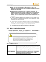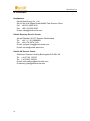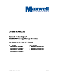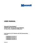
1
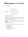
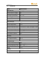
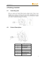
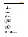
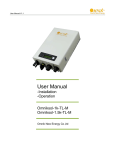
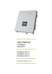
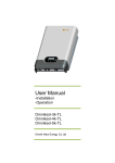
User Manual V1.3 User Manual -Installation -Operation Omniksol-M248 Omnik New Energy Co.,Ltd. User Manual V1.3 Catalog 1. Important Safety Information ................................................................................................... 2 1.1 Read it First ...................................................................................................................... 2 1.2 Safety Instructions ........................................................................................................... 2 2. Omnik Micro-Inverter System ................................................................................................... 4 2.1 How it work ...................................................................................................................... 4 2.2 Monitoring Micro-Kit ....................................................................................................... 4 2.3 Optimal Reliability ............................................................................................................ 4 2.4 Easy of Design .................................................................................................................. 5 3. Product Information .................................................................................................................. 6 3.1 Overview .......................................................................................................................... 6 3.2 Major Characteristics ....................................................................................................... 6 3.3 Datasheet ......................................................................................................................... 7 4. Packing checklist ....................................................................................................................... 9 4.1 Assembly parts ................................................................................................................. 9 4.2 Product Description ......................................................................................................... 9 4.3 Further information ....................................................................................................... 10 5. Planning of Micro-Inverter Installation ................................................................................... 11 5.1 Explanations of Symbols on Inverter ............................................................................. 11 5.2 Lightning and Surge Suppression ................................................................................... 11 6. Micro-Inverter Mounting and Wiring ...................................................................................... 12 6.1 Tool Required ................................................................................................................. 12 6.2 Installation Diagram ....................................................................................................... 12 6.3 Installation Steps ............................................................................................................ 13 6.4 Cable end installation .................................................................................................... 15 7. Commissioning and Operation ................................................................................................ 17 7.1 Energize the System ....................................................................................................... 17 7.2 M248 Operation............................................................................................................. 17 8. Troubleshooting and Maintenance ......................................................................................... 19 8.1 Status LED Indications and Error Reporting ................................................................... 19 8.2 Troubleshoot an Inoperable Micro-Inverter .................................................................. 20 8.3 Micro-Inverter Maintenance ......................................................................................... 21 9. Contact .................................................................................................................................... 22 1 User Manual V1.3 1. Important Safety Information 1.1 Read it First This manual contains important instructions for use during installation and maintenance of the Omnik M248 Micro-Inverter. To reduce the risk of electrical shock, and to ensure the safe installation and operation of the Micro-Inverter, the following safety symbols appear throughout this document to indicate dangerous conditions and important safety instructions. DANGER DANGER indicates a hazardous situation which, if not avoided, will result in death or serious injury. WARNING WARNING indicates a hazardous situation which, if not avoided, can result in death or serious injury or moderate injury. NOTICE NOTICE indicates a situation that can result in property damage, if not avoided. 1.2 Safety Instructions Do not use Omnik equipment in a manner not specified by the manufacturer. Doing so may cause death or injury to persons, or damage to equipment. Be aware that only qualified personnel should install or replace the Omnik Micro-Inverters and the Cable and accessories. Do not attempt to repair the Omnik Micro-Inverter; it contains no user-serviceable parts. If it fails, contact Omnik customer service to start 2 User Manual V1.3 the replacement process. Tampering with or opening the Omnik Micro-Inverter will void the warranty. If the AC cable on the Micro-Inverter is damaged or broken, do not install the unit. Before installing or using the Omnik Micro-Inverter, read all instructions and cautionary markings in the technical description and on the Omnik Micro-Inverter System and the PV equipment. Connect the Omnik Micro-Inverter to the utility grid only after you have completed all installation procedures and after receiving prior approval from the electrical utility company. Be aware that the body of the Omnik Micro-Inverter is the heat sink. Under normal operating conditions, the temperature is 20°C above ambient, but under extreme conditions the Micro-Inverter can reach a temperature of 80°C (176°F). To reduce risk of burns, use caution when working with Micro-Inverters. Do not disconnect the PV module from the Omnik Micro-Inverter without first removing AC power. Be aware that the M248 has field-adjustable voltage and frequency trip points that you may need to set, depending upon local requirements. Only an authorized installer with the permission and following requirements of the local electrical utility should make adjustments. 3 User Manual V1.3 2. Omnik Micro-Inverter System The Omnik Micro-Inverter System is the world’s most technologically advanced inverter system for use in utility-interactive applications. This manual details the safe installation and operation of the Omnik Micro-Inverter. The two key elements of an Omnik Micro-Inverter System include the: Omnik M248 Micro-Inverter Omnik Micro-Kit This integrated system maximizes energy harvest, increases system reliability, and simplifies design, installation and management. 2.1 How it work The Omnik Micro-Inverter maximizes energy production from your photovoltaic (PV) array. Each Omnik Micro-Inverter is individually connected to one PV module in your array. This unique configuration means that an individual Maximum Peak Power Point Tracker (MPPT) controls each PV module. This ensures that the maximum power available from each PV module is exported to the utility grid regardless of the performance of the other PV modules in the array. That is, although individual PV modules in the array may be affected by shading, soiling, orientation, or PV module mismatch, the Omnik Micro-Inverter ensures top performance for its associated PV module. The result is maximum energy production from your PV system. 2.2 Monitoring Micro-Kit Once you install Micro-Kit and provide an ethernet connection to your broadband router or modem, the Omnik Micro-Inverters automatically begin reporting to the Omnik Micro-Kit web server. The Micro-Kit software presents current and historical system performance trends, and it informs you of PV system status. 2.3 Optimal Reliability Micro-Inverter systems are inherently more reliable than traditional inverters. The distributed nature of a Micro-Inverter system ensures that there is no single point of system failure in the PV system. Omnik Micro-Inverters are designed to operate at full power at ambient 4 User Manual V1.3 temperatures as high as 65℃(150℉). The Micro-Inverter housing is designed for outdoor installation and complies with the NEMA 6 environmental enclosure rating standard: IP65 rating definition: Indoor or outdoor use primarily to provide a degree of protection against hose-directed water, the entry of water during occasional temporary submersion at a limited depth, and damage from external ice formation. NOTE: To ensure optimal reliability and to meet warranty requirements, the Omnik Micro-Inverter must be installed according to the instructions in this manual. 2.4 Easy of Design PV systems using Omnik Micro-Inverters are very simple to design and install. You will not need string calculations, and you can install individual PV modules in any combination of PV module quantity, type, age and orientation. You won’t need to install cumbersome traditional inverters. Each Micro-Inverter quickly mounts on the PV racking, directly beneath each PV module. Low voltage DC wires connect from the PV module directly to the co-located Micro-Inverter, eliminating the risk of personnel exposure to dangerously high DC voltage. 5 User Manual V1.3 3. Product Information 3.1 Overview 3.2 Major Characteristics Omnik Micro-Inverter has following characteristics which make Omnik Micro-Inverter “High Efficiency, High Reliability, High Cost Effective Ratio” Wide DC input voltage and current range. Wide MPP voltage range ensure high yield under various weather conditions. High MPP tracking accuracy, ensure the minimum power loses during converting. Complete set of protection methods. Also, following protection methods are integrated in Omnik Micro-inverter: Internal overvoltage Ground fault protection Grid monitoring Ground fault current monitoring DC current monitoring 6 User Manual V1.3 3.3 Datasheet Model Omniksol-M248 Input Data (DC) Recommended input power Maximum input DC voltage Min./Max. Start voltage Peak power tracking range Operating range Maximum DC short circuit current Maximum input current DC Feedback current 160-300W 50V 28V /50V 28V~40V 22V~40V 15A 9.5A 0A Output Data (AC) Maximum output power Nominal output current Maximum output current Maximum output fault current Over Current Protection Value Nominal output voltage Nominal output frequency Power factor Total Harmonic Distortion Maximum units per branch 248W 1.07A 1.11A 1.25Arms over 3 cycles, 26.8A peak, 2.36ms 6.65 Matching grid demand Matching grid demand >0.99 <3% 15 Efficiency Peak inverter efficiency CEC weighted efficiency Nighttime power consumption 94.5% 93.5% 120mW Mechanical Data Enclosure environmental rating Ambient temperature range Operating temperature range (internal) Dimensions (WxHxD) Weight IP65 -40℃~+65 ℃ -40℃~+85℃ 221mm/169mm/36mm 1.7kg Features Communication PLCC (Power Line Carrier Communication) Warranty 15 Years 7 User Manual V1.3 Cooling Pollution Degree 8 Natural 1 User Manual V1.3 4. Packing checklist 4.1 Assembly parts After you receive the Omnik Micro-Inverter, please check if there is any damage on the carton, and then check the inside completeness for any visible external damage on the Micro-Inverter or any accessories. Contact your dealer if anything is damaged or missing. 4.2 Product Description Item Description A DC connectors B AC connector C Led D Grounding hole E Wall bracket hole F Porting cover 9 User Manual V1.3 4.3 Further information If you have any further questions concerning the type of accessories or installation, please check our website www.omnik-solar.com or contact our service hotline. 10 User Manual V1.3 5. Planning of Micro-Inverter Installation 5.1 Explanations of Symbols on Inverter Symbol Description Dangerous electrical voltage This device is directly connected to public grid, thus all work to the inverter shall only be carried out by qualified personnel. NOTICE, danger! This device directly connected with electricity generators and public grid. Danger of hot surface The components inside the inverter will release a log of heat during operation, DO NOT touch aluminum housing during operating. An error has occurred Please go to Chapter 10 “Trouble Shooting” to remedy the error. This device SHALL NOT be disposed of in residential waste Please go to Chapter 9 “Recycling and Disposal” for proper treatments. No unauthorized perforations or modifications Any unauthorized perforations or modifications are strictly forbidden, if any defect or damage (device/person) is occurred, Omnik shall not take any responsibility for it. 5.2 Lightning and Surge Suppression Omnik Micro-Inverters have integral surge protection, greater than most traditional inverters. However, if the surge has sufficient energy, the protection built into the Micro-Inverter can be exceeded, and the equipment can be damaged. For this reason, Omnik recommends that you protect your system with lightning and/or surge suppression devices. In addition to having some level of surge suppression, it is important to have insurance that protects against lightning and electrical surges. 11 User Manual V1.3 6. Micro-Inverter Mounting and Wiring 6.1 Tool Required 6.2 Installation Diagram 01. PV module 02 .Micro inverter 03 .Junction box 04. Mounting rail 05 .Grounding line 06 .AC power cable 07. DC connectors 08 .AC connector 09 .T-connector of AC power cable 10 .Cable end cap 11 .T connector temporary plug cap 12 .Plug sealing cap 13. Unlocking tool DANGER DO NOT connect or disconnect the PV module and Omnik Micro-Inverter without first removing AC power from the PV system. 12 User Manual V1.3 10 08 01 09 06 02 05 07 12 08 11 03 04 13 6.3 Installation Steps Installing the Micro inverter System involves several key steps. Each step listed here is detailed in the following page. Step1: Check system configuration Step2: Connect AC power cable and fix T-connector Step3: Install inverter Step4: Ground connection Step5: Install the end cap of AC power cable Step6: Connect inverter AC output and access AC power cable to AC bus box Step7: Statistics installation diagram Step8: Connect PV module Step9: Install Micro-Kit 13 User Manual V1.3 WARNING Allow a minimum of 1.9cm between the roof and the bottom of the microinverter. Also allow 1.3cm between the back of the PV module and the top of the microinverter. WARNING You must install the microinverter under the module, out of rain and sun. Do not mount the microinverter in a position that allows long-term exposure to direct sunlight or in a vertical orientation that allows water to collect in the DC connect recess. WARNING The microinverter is not equipped to operate in environments that have particular flammability or explosive conditions. NOTICE If this microinverter is installed in Australia, Electrical Installation & Maintenance shall be conducted by licensed electrician and shall comply with Australia National Rules. NOTICE During installation, if the arrays are mono-crystalline or polycrystalline solar cells, the array should be floating. If the arrays are thin-film cells, the PV negative pole should be grounded. 14 User Manual V1.3 6.4 Cable end installation 18mm~25mm Strip cable jacket 18mm~25mm 18mm~25mm 18mm~25mm Disassemble the Seal, Clamp ring, Nut, then Insert through the cable Insert each wires into the holes 18mm~25mm Push he cable to the end. Gently try to pull out the cable. It should not be pulled out Screw the sealing nut into body tightly with a force of 25 Kgf.cm 15 User Manual V1.3 Note: Wire size/ Inner jacket OD Max: 10AWG (6mm2) / Max OD 4.65mm Recommended sealing nut torque: 25Kgf.cm (2.5N.m) Recommended installation temperature: 20℃ (60℉) upward Avoid oil and gasoline Waterproof rote :IP67 16 User Manual V1.3 7. Commissioning and Operation Please notice the symbols. WARNING Qualified personnel only may connect the Omnik Micro-Inverter to the utility grid after receiving prior approval from the electrical utility company. WARNING Ensure that all AC and DC wiring is correct. Ensure that none of the AC and DC wires are pinched or damaged. Ensure that all AC junction boxes are properly closed. 7.1 Energize the System 1. Turn ON the AC disconnect or circuit breaker for each Micro-Inverter AC branch circuit. 2. Turn ON the main utility-grid AC circuit breaker. Your system starts producing power after a five-minute wait time. 3. The Omnik Micro-Inverters begins communicating over the power lines to the Micro-Kit. The time required for all Micro-Inverters to report to the Micro-Kit with the number of Micro-Inverters in the system. The first units should be detected within 15 minutes but the entire system could take hours to detect. 4. The M248 has field-adjustable voltage and frequency trip points. If adjustments are required by your local utility, the installer can use the Micro-Kit to Manage the Grid Profile after all Micro-Inverters have been detected. 7.2 M248 Operation The Omnik Micro-Inverter is powered on when sufficient DC voltage from the PV module is applied. The Status LED of each Micro-Inverter will blink green to indicate normal start-up operation approximately one minute after 17 User Manual V1.3 DC power is applied. You may need to use a handheld mirror to view indicator lights on the undersides of the Micro-Inverters. 18 User Manual V1.3 8. Troubleshooting and Maintenance Adhere to all the safety measures described throughout this manual. Qualified personnel can use the following troubleshooting steps if the PV system does not operate correctly. WARNING Do not attempt to repair the Omnik Micro-Inverter; it contains no user-serviceable parts. If the Micro-Inverter fails, contact Omnik customer service to obtain an RMA (return merchandise authorization) number and start the replacement process. 8.1 Status LED Indications and Error Reporting Startup LED Operation: The Status LED of each Micro-Inverter blinks green to indicate normal start-up operation approximately one minute after DC power is applied. Red blinks after DC power is first applied to the Micro-Inverter indicate a failure during Micro-Inverter startup. Post-Startup LED Indications: Use a handheld mirror to view indicator lights on the undersides of the Micro-Inverters: Flashing Green: Indicates normal operation. Flashing Red: Indicates that the Micro-Inverter is not operating normally. The Micro-Inverter does not sense that the utility grid is within voltage/frequency specifications. The Micro-Inverter cannot produce power until this is resolved. 19 User Manual V1.3 8.2 Troubleshoot an Inoperable Micro-Inverter To troubleshoot an inoperable Micro-Inverter, follow the steps in the order shown. WARNING: Be aware that only qualified personnel should troubleshoot the PV array or the Omnik Micro-Inverter. Best Practice: Never disconnect the DC wire connectors under load. Ensure that no current is flowing in the DC wires prior to disconnecting. If necessary, use an opaque covering to cover the PV module prior to disconnecting the PV module. Always disconnect AC power before disconnecting the PV module wires from the Omnik Micro-Inverter. The AC connector of the Micro-Inverter is suitable as a disconnecting means. WARNING: The AC and DC connectors on the cabling are rated as a disconnect only when used with an Omnik Micro-Inverter. WARNING: The Omnik Micro-Inverters are powered by DC power from the PV modules. Make sure you disconnect the DC connections and reconnect DC power to watch for the LED blinks one minute after DC is applied. 1. Make sure AC breakers and disconnects are closed. 2. Check the connection to the utility grid and verify that the utility voltage is within allowable ranges shown in the Technical Data section on page 9 of this manual. 3. Verify that AC line voltage at all solar power circuit breakers at the load center and subpanels is within the ranges shown in the following table. 4. Verify that AC line voltage at the junction box for each AC branch circuit are within the ranges are shown in the following table: 230 or 240 Volt AC, Single Phase L to N 184 to 264 VAC 208 Volt AC, Three Phase (L1 to L2) or (L2 to L3) or( L3 to 183 L1) VAC 5. Using an Omnik disconnect tool, disconnect the AC cable for the Micro-Inverter in question from the Cable. 6. Verify that utility power is present at the Micro-Inverter by measuring line to line and line to neutral at the Cable connector. 7. Visually check that the AC branch circuit connections (Cable and AC connections) are properly seated. Reseat if necessary. Check also 20 User Manual V1.3 for damage, such as rodent damage. 8. Make sure that any upstream AC disconnects, as well as the dedicated circuit breakers for each AC branch circuit, are functioning properly and are closed. 9. Disconnect and re-connect the DC PV module connectors. The Status LED of each Micro-Inverter will blink green to indicate normal start-up operation soon (less than one minute) after DC power is applied. The LED subsequently resumes normal operation if the Grid is present.. 10. Attach an ammeter clamp to one conductor of the DC cables from the PV module to measure Micro-Inverter current. This will be under one Amp if AC is disconnected. 11. Check the DC connections between the Micro-Inverter and the PV module. The connection may need to be tightened or reseated. If the connection is worn or damaged, it may need replacement. 12. Verify with your utility that line frequency is within range. 8.3 Micro-Inverter Maintenance Routine Maintenance, although not mandatory, is recommended to maintain efficient operation of the PV installation. WARNING It is recommended that maintenance operations be only performed by qualified personnel or Omnik personnel. The maintenance schedule may vary depending on the environmental conditions of the installation site. Routine Maintenance Annual Cleaning Conduct an annual visual inspection(where possible) on the various components(DC cables, Micro-Inverters and AC cables) to check for dust, dirt, moisture and water seepage. Clean the equipment if necessary. Clean using compressed air, a vacuum cleaner or special brushes, if possible. Annual Operations Check that there has been no drastic change in the installation conditions that might have a negative influence on radio communication with the micro-inverters. 21 User Manual V1.3 9. Contact Headquarter Omnik New Energy Co., Ltd. A4-414 No.218 Xinghu Road bioBAY Park Suzhou China Cel: +86 512 6956 8216 Fax: +86 512 6295 6682 E-mail: [email protected] Omnik Germany Service Center An der Pikardie 6 01277 Dresden Deutschland Tel: +49(0)351 30986031 Cel: +49 (176) 3074 3149 E-mail: [email protected] E-mail: [email protected] Omnik UK Service Center 48 Anchor Crescent Hockley Birmingham B18 5SL UK Tel: +44 (7718) 123747 Tel: +44 (7902) 438754 E-mail: [email protected] E-mail:[email protected] 22 User Manual V1.3 Omnik Netherlands Service Center Nicolaas Beetslaan 20, 2041 NN Zandvoort, The Netherlands Tel: +31 23 751 4902 Cel: +31 62 516 1342 E-mail: [email protected] Omnik Shanghai Office Room 05,16F Suncome Liauw's Plaza No.738 Shangcheng Rd Shanghai China Tel: +86 21 5838 5613 Fax: +86 21 5838 5391 E-mail: [email protected] 23