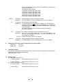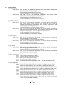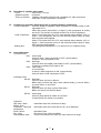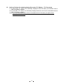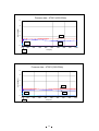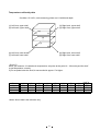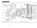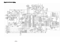
1
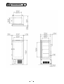
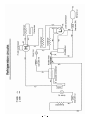
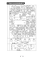
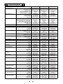
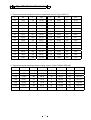
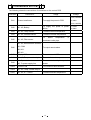
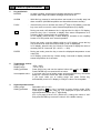
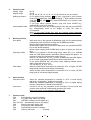
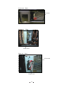
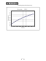
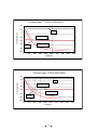
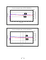
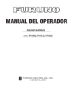
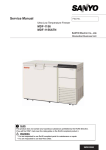
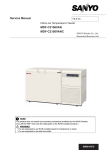
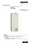
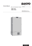
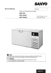
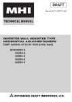
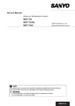
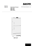
Service Manual Ultra-low Temperature Freezer MDF-U4186S SANYO Electric Co., Ltd. Biomedical Business Division 5R+6 7KLVSURGXFWGRHVQRWFRQWDLQDQ\KD]DUGRXVVXEVWDQFHVSURKLELWHGE\WKH5R+6'LUHFWLYH 9OUWILLFIND@23&MARKNEARTHERATINGSODWHRQWKH5R+6FRPSOLDQWSURGXFW :$51,1* <RXDUHUHTXHVWHGWRXVH5R+6FRPSOLDQWSDUWVIRUPDLQWHQDQFHRUUHSDLU <RXDUHUHTXHVWHGWRXVHOHDGIUHHVROGHU SM9910125 Effective models This service manual is effective following models. Model name MDF-U4186S Product code 823 198 52 823 198 53 823 198 54 823 198 55 Voltage and Frequency 220V 50Hz 220V 60Hz 230/240V 50Hz 220V 50Hz Contents 㩷 㪧㪸㪾㪼㩷 ---------------------------------------------- 1 -Structural specifications 1 -Control specifications 2 -Performance specifications 3 Dimensions ---------------------------------------------- 4 Cooling unit parts ---------------------------------------------- 5 Refrigeration circuits ------------------------------------------- 6 Components on PCB ------------------------------------------- 7 ---------------------------------------------- 8 Specifications of sensor -------------------------------------- 9 Connections on PCB -------------------------------------- 10 Control specification -------------------------------------- 11 Parts layout --------------------------------------------------- 19 Test data --------------------------------------------------- 21 -Pull up characteristics 21 -Pull down characteristics 22 -Current consumption 23 -Pressure 24 -Temperature uniformity 25 Specifications Electrical parts Wiring diagram --------------------------------------------- 26 Circuit diagram --------------------------------------------- 27 Instruction manual ---------------------------------------------- 28 㩷 Specifications ŶStructural specifications Item MDF-U4186S External dimensions W870 x D780 x H1975 (mm) Internal dimensions W620 x D515 x H1200 (mm) Effective capacity 382 L Exterior Painted steel Interior Painted steel Outer door Painted steel Inner door 2doors, ABS resin panel with stainless frame Insulation Rigid-polyurethane foamed-in place Exterior Painted steel Interior Painted steel Shelf 3shelves, stainless steel Caster 4pcs,㧔2 leveling foot at front㧕 Access port Ǿ40mm, 1 place (left side) Net weight 281 kg Cooling performance -86͠ at center part of freezing room㧔AT30͠, no load㧕 Compressor H side: 1100W, hermetic type L side: 1100W, hermetic type Refrigerant H side: HFC refrigerant(R-407D㧕 L side: HFC refrigerant (R-508㧕 Refrigerant oil Ze-NIUS32SA Evaporator Tube on sheet Condenser H side㧦Fin and tube L side㧦Shell and tube Power supply Battery Accessories Optional component Local voltage For power failure alarm; Nickel-cadmium battery(5N-270AA), DC6V, 270mAh 1 set of keys, 1 scraper, 2 rubber caps Inventory rack (IR-220U), Automatic temperature recorder(MTR-85H), Back-up system (CVK-UB2);LCO2 1 ŶControl specifications Item Temperature controller Temperature sensor Temperature display High temp. alarm Alarm Door Filter Power failure Remote alarm Battery life Fan motor life Control panel Self diagnosis function Compressor protection MDF-U4186S Microprocessor controlled system Pt.100ǡ LED digital display㧔1͠ graduation㧕 Selectable with 10͠ or 15͠.(Initial:10͠) ALARM lamp blinks and intermittent buzzer beeps with 12 min. of delay Remote alarm contact: Normal Open, Normal Close Max; 30VDC, 2A Temperature alarm turns on during power failure (not linked with buzzer) DOOR lamp is lit when outer door is left opened. Filter check lamp (FILTER) is lit with intermittent buzzer beeps. ALARM lamp blinks with intermittent buzzer beeps, remote alarm outputs. 3P remote alarm terminal: Maximum 30VDC, 2A NC-COM, NO-COM Outputs during temperature alarm and power failure alarm PV and ‘F1’ are alternately displayed Accumulating time: Approx. 3 years PV and ‘F2’ are alternately displayed. Accumulating time: Approx. 6 years Lamp: ALARM, FILTER CHECK, CO2 BACK UP BUZZER: Alarm buzzer stop key ALARM: Alarm test key PV/SV: Temperature setting key ENT: Enter key 㧪: Digit shift key ȁ: Numerical value shift key When any failure occurs among the temperature sensor, filter sensor, cascade sensor and AT sensor; Error code and internal temp.(PV) are alternately displayed. Remote alarm contact turns on and buzzer beeps. When the temperature of cascade sensor is -34͠ or lower, L side compressor is turned on. When the temperature of cascade sensor is -12͠ or higher, L side compressor is turned off. When unit detects filter sensor temperature +60͠ or higher, H side compressor is turned off. Overload relay 2 ŶPerformance specifications <MDF-U4186S> Cooling performance Temperature control range Power source Rated power consumption Noise level Maximum pressure -86͠ at center part of freezing room (AT 30͠, no load) -20͠ to -86͠ (AT 30͠, no load) 220V, 50Hz 220V, 60Hz 1010W 230V, 50Hz 1110W 1070W 49 dB [A scale] 2.18 MPa * Specifications will be subject to change without notice. 3 240V, 50Hz 1110W Dimensions 4 Cooling unit parts <MDF-U4186S> Item Compressor 220V, 60Hz 220V, 50Hz 230/240V, 50Hz Refrigerant oil Cooling system Specifications H side L side Compressor code: 7FB-0-M101-001-06 Compressor code: 7FB-0-M101-001-04 Compressor code: 7FB-0-M101-001-05 Ze-NIUS32SA Charged q’ty: 850cc Forced air cooling㧔partially㧕 Oil cooler Compressor type: KS370J1NS-7A Compressor type: KS370J1NS-4A Compressor type: KS370J1NS-4A1 Ze-NIUS32SA Charged q’ty: 850cc Forced air cooling㧔partially㧕 Oil cooler Condenser Type Condenser Pre-condenser Frame pipe Evaporator Type Capillary tube Resistance PSIkg/cm2 Length Outer diameter Inner diameter Refrigerant Oil additive Dryer Condensing fan Condensing fan motor Type Oil separator Fin and tube 12 columns x 3 lines P4mm Fin 62pcs. W 250mm Ǿ6.35mm Cascade condenser Shell and tube Ǿ80mm Cascade condenser Coil pipe Ǿ6.35mm ʊ ʊ Tube on sheet Ǿ9.52mm Ex. capillary 78 PSI/G 5 kgf/cm2 34 PSI/G 3000mm Ǿ2.4mm Ǿ1.2mm 2000mm Ǿ1.8mm (Ǿ0.65mm) 500mm Ǿ2.4mm Ǿ1.2mm R-407D Charged q’ty: 391g R-508 Charged q’ty: 310g n-Pentane n-Pentane Charged-q’ty: 24g Charged q’ty: 44g 4A-XH-9 Charged q’ty: 18g 4A-XH-6 Charged q’ty: 58g Ǿ230 mmޔ4 blades Material: ABS SE4-E11L5P SPK-0S02S2 (810-4-2008) ʊ 5 6 Components on PCB 7 Electrical parts MDF-U4186S Compressor (H),䋨L) Starting relay (H),䋨L) Overload relay (H),䋨L) Starting capacitor (H),䋨L) Running capacitor (H),䋨L) Condensing fan motor Cap.tube heater Door heater Temp. control relay (H)(L) Temp. sensor Cascade sensor Filter sensor A.T. sensor Power transformer Power transformer (for PCB) Breaker switch Battery switch Door switch Test switch (for CVK-UB2, option) Back up switch (for CVK-UB2, option) Solenoid valve (for CVK-UB2, option) Power transformer (for CVK-UB2, option) 220V, 50Hz 230/240V, 50Hz 220V, 60Hz Type KS370J1NS-4A KS370J1NS-4A1 KS370J1NS-7A Compressor code 7FB-0-M101-001-04 7FB-0-M101-001-05 7FB-0-M101-001-06 Rated voltage 220/230V, 50Hz 230/240V, 50Hz 220V, 60Hz Winding resistance 㧔C-S) 2.53㱅 2.53㱅 1.64㱅 Winding resistance 㧔C-R) 4.8㱅 4.8㱅 3.35㱅 AMVL-300A AMVL-300A Type AMVL-300A Pick up voltage 185~217VAC 185~217VAC 215~247VAC Drop out voltage 60~120VAC 60~120VAC 69~132VAC Parts code 626 100 1503 626 100 1503 Type MRA99953-9201 MRA99953-9201 MRA99954-9201 Action to the temp. (no current) ON 69+/-11㷄 69+/-11㷄 69+/-11㷄 Action to the temp. (no current) OFF 135+/-5㷄 135+/-5㷄 135+/-5㷄 22.5A 29.5A Action to the current (AT25͠) 22.5A Operation time 6~16sec 6~16sec 6~16sec Parts code 624 226 3166 624 226 3166 624 226 3173 Rating 100MF, 250VAC 100MF, 250VAC 160MF, 250VAC Rating 25MF, 400VAC 25MF, 400VAC 25MF, 400VAC Type SE4-E11L5P SE4-E11L5P SE4-E11L5P Rating 220-240VAC 220-240VAC 220-240VAC Parts code 624 225 6236 624 225 6236 624 225 6236 Rating 12W, 100V 12W, 100V 12W, 100V Resistance (25͠) 846㱅 846㱅 846㱅 Parts code 624 198 7902 624 198 7902 624 198 7902 Rating 27.6W, 230V 27.6W, 230V 27.6W, 230V Resistance (25͠) 400㱅 400㱅 400㱅 Type G4F-11123T G4F-11123T G4F-11123T 20A, 12VDC 20A, 12VDC 20A, 12VDC Contact capacity Parts code 624 173 2397 624 173 2397 624 173 2397 Type PT-100㱅 PT-100㱅 PT-100㱅 Type 502AT 502AT 502AT Rating 5k㱅, 25㷄 5k㱅, 25㷄 5k㱅, 25㷄 Type 502AT 502AT 502AT Rating 5k㱅, 25㷄 5k㱅, 25㷄 5k㱅, 25㷄 Type 502AT 502AT 502AT Rating 5k㱅, 25㷄 5k㱅, 25㷄 5k㱅, 25㷄 Type ATR-C105 ATR-C105 ATR-C105 200/225/240V 200/225/240V 200/225/240V Primary 100V, 50VA 100V, 50VA 100V, 50VA Secondary Parts code 624 204 5786 624 204 5786 624 204 5786 Type A-3578 A-3578 A-3578 100V, 6.2VA 100V, 6.2VA Rating 100V, 6.2VA Parts code 624 224 6381 624 224 6381 624 224 6381 Type BAM215131 BAM215131 BAM215131 250V, 15A 250V, 15A Rating 250V, 15A Parts code 624 215 4235 624 215 4235 624 215 4235 Type SLE6A2-5 SLE6A2-5 SLE6A2-5 250VAC, 4A 250VAC, 4A Rating 250VAC, 4A Parts code 624 213 1472 624 213 1472 624 213 1472 Type PS-500-605 PS-500-605 PS-500-605 200V, 0.5A 200V, 0.5A Rating 200V, 0.5A Parts code 624 171 3228 624 171 3228 624 171 3228 Type 8R2021 8R2021 8R2021 125VAC, 3A 125VAC, 3A Rating 125VAC, 3A Parts code 624 194 3984 624 194 3984 624 194 3984 Type HLS208N HLS208N HLS208N 125VAC, 5A 125VAC, 5A Rating 125VAC, 5A Parts code 624 169 9690 624 169 9690 624 169 9690 Type X8264D9 X8264D9 X8264D9 Rating 24VDC 24VDC 24VDC Parts code 624 215 2224 624 215 2224 624 215 2224 Type ATR-K285T ATR-K285T ATR-K285T 100/115/230V 100/115/230V 100/115/230V Primary 23V, 1.2A 23V, 1.2A 23V, 1.2A Secondary Parts code 624 203 9624 624 203 9624 624 203 9624 8 Specifications of sensor 1. Temperatures and resistance values in temperature sensor (Type: 502AT-1) 㷄 kȍ 㷄 kȍ 㷄 kȍ 㷄 kȍ 䋭50 154.5 䋭36 71.80 䋭22 35.65 0 13.29 䋭49 145.9 䋭35 68.15 䋭21 33.99 5 10.80 䋭48 137.8 䋭34 64.71 䋭20 32.43 10 8.84 䋭47 130.2 䋭33 61.48 䋭19 30.92 15 7.20 䋭46 123.1 䋭32 58.43 䋭18 29.50 20 6.01 䋭45 116.5 䋭31 55.55 䋭17 28.14 25 5.00 䋭44 110.2 䋭30 52.84 䋭16 26.87 30 4.17 䋭43 104.4 䋭29 50.23 䋭15 25.65 35 3.50 䋭42 98.87 䋭28 47.77 䋭14 24.51 40 2.96 䋭41 93.70 䋭27 45.45 䋭13 23.42 45 2.51 䋭40 88.85 䋭26 43.26 䋭12 22.39 50 2.13 䋭39 84.18 䋭25 41.19 䋭11 21.41 55 1.82 䋭38 79.80 䋭24 39.24 䋭10 20.48 60 1.56 䋭37 75.67 䋭23 37.39 䋭5 16.43 65 1.35 2. Temperatures and resistance values in temp. sensor (Type: Pt100ȍ- NEW JIS) 㷄 ȍ 㷄 ȍ 㷄 ȍ 㷄 ȍ 䋭170 31.32 䋭100 60.25 -30 88.22 40 115.54 䋭160 35.79 䋭90 64.30 -20 92.16 50 119.40 䋭150 39.82 䋭80 68.33 -10 96.09 60 123.24 䋭140 43.87 䋭70 72.33 0 100.00 70 127.07 䋭130 48.00 䋭60 76.33 10 103.90 80 130.89 䋭120 52.11 䋭50 80.31 20 107.80 90 134.70 䋭110 56.19 䋭40 84.27 30 116.70 100 138.50 9 Connections on PCB The following shows the connections of connectors on the control PCB. Connects to Connector Usage Voltage #1-#2; 10.3VAC CN1 Power transformer To supply the power to PCB. #3; GND #4-#5; 18.5VAC CN2 #1 - #2; Battery To supply the power in power #1; 6VDC failure #2; GND CN3 #1 - #3; Temp. sensor To detect internal temperature CN4 #1 - #2; Cascade sensor To detect cascade temperature CN5 #1 - #2; Filter sensor To detect temperature in condenser outlet pipe. #1 - #5; Remote alarm terminal CN6 #1; COM. #3; N.O. To output remote alarm #5; N.C. CN7 Display PCB To connect each LEDs. CN8 #1 - #2; Temp. control relay L To control internal temperature. #1; Cap. tube heater To conduct electricity in cap. tube #2; To power supply line heater. CN13 Control PCB To connect to each switches. CN14 #1 - #3; Temp. control relay H CN15 #1 - #2; A.T. sensor CN9 To detect ambient temperature 10 #1-#2; 12VDC Control specification 1. Key and Switch BUZZER : In alarm condition, buzzer stops sounding with this key pressed. Remote alarm output and alarm message would not be off. ALARM : With this key pressed to activate alarm test mode to be forcibly step into alarm condition (ALARM lamp blinks and intermittent buzzer sounds). PV/SV : Press this key once to activate set mode (2nd digit in LED blinks), press the key once more to revert to current internal temperature (PV) display. During set mode, shift between the 1st digit and the 2nd digit. In PV display, press the key over 5 seconds to display filter sensor temperature for 3 seconds. (digit of decimal point is not displayed) In PV display, press the key 5 times during 5 seconds to turn capillary heater on for the period set in normal operation. During set mode, count the blinking digit up. In PV display, press the key over 5 seconds to enter the function mode. (“F00” is displayed) In PV display, press the key for 5 times in 5 seconds to display the value of decimal point for 3 seconds. (Ex. -80.3㷄 㸢 803) ENTER : During set mode, press the key to store the displayed temperature as set value (SV). In PV display, press the key 5 times during 5 seconds to display cascade sensor temperature for 3 seconds. 2. Temperature control Setting range : -20㷄䌾-95㷄 Display range : -170㷄䌾50㷄 Setting procedure : Press PV/SV key and set the required value with key and key. Press ENTER key to memorize the set value. Unacceptable value : If you input value out of setting range and press ENTER key, the buzzer beeps for 1 second to inform the value unacceptable. If you input value out of setting range and press PV/SV key, automatically revert to PV display to notify the value is unacceptable. 3. High temperature alarm Setting range : Selectable 10㷄 or 15㷄 Setting procedure : Keep pressing key over 5 seconds to enter function mode (F00). Press again to count the value up. “F01” displayed to input the value of high temperature alarm. (the 1st digit blinks) (Ex. If you want to set at 15㷄 (initial 10㷄), change the value to “001” and press ENTER key to store the value in non-volatile memory. 11 4. Function mode Setting range Display range : 00~32 : 00~39 00, 02, 04, 05, 08, 12~14, 18, 19, 23, 26~30 and 33~39 are unused. Setting procedure : In PV display, keep pressing key over 5 seconds to enter function mode (F00 is displayed). Change the blinking 1st digit to desired function code with key and 㩷 key. Press ENTER key to be function code available. If you input above unused function code and press ENTER key, automatically revert to PV display. Unacceptable value : Even If you input value out of setting range (F33~39) and press ENTER key, automatically revert to PV display to notify the value is unacceptable. Note) If you press PV/SV key with any function mode displayed, automatically revert to PV display to ignore the displayed function mode. 5. 6. 7. Warning function Door alarm : High temp. alarm : Filter alarm : Other function Cascade control : Auto return : With outer door is left opened, ALARM lamp (red) is lit. the buzzer beeps intermittently with 30 minutes of delay and ALARM lamp blinks. Remote alarm terminal does not output. Buzzer beeps again with 30 minutes of delay after you pressed BUZZER key to stop buzzer beeping. Buzzer stops beeping and ALARM lamp is gone off when you shut the door. When PV is reached to SV+SVH (high temp. alarm SV) +1 or, ALARM lamp and LED display blinks, intermittent buzzer beeps with approx. 12 minutes of delay and remote alarm output turns on. When PV is reached to SV+ SVH or lower, ALARM lamp and LED display go off, buzzer stops beeping and remote alarm output turns off. If you press BUZZER key, the buzzer stops beeping instead remote alarm output does not turn off. You can set SVH at 10㷄 in F01. When the filter sensor temperature is reached to 45㷄 or higher, FILTER lamp is flash and the buzzer beeps intermittently. When the filter sensor temperature is reached to 41㷄 or lower, FILTER lamp goes off and buzzer stops beeping. When the cascade temperature is reached to -34㷄 or lower during pull-down, Compressor L would be turned ON. When the cascade temperature is reached to -12㷄 or higher during pull-up, Compressor H would be turned OFF. If there is not any key operation for 90 seconds in SV set mode and function code set mode, automatically reverts to PV mode. Note) Auto return is not worked in F09 and F10. Function mode F00 Automatically revert to PV display F01 SVH (high temp. alarm SV) setting F03 Indication of battery accumulation time F02, F04, F05 Automatically revert to PV display F06 Service code input (code: 384) F07 Temperature Zero Adjustment F08 Automatically revert to PV display F09 (Factory test mode ………… Unused) 12 F10 F11 F12~F14 F15 F16 F17 F18, F19 F20 F21 F22 F23 F24 F25 F26~F30 F31 F32 F33~F39 (Factory test mode ………… Unused) (Cascade temperature Zero Adjustment ……… Unused) Automatically revert to PV display Indication of temperature in AT sensor (Timer speed-up mode ……… Unused) Model code setting (non-volatile memory initialization ……… Unused) Automatically revert to PV display Capillary heater is forcibly turned off (Communication ID setting ……… Unused) (Communication mode setting ………Unused) Automatically revert to PV display PV display (decimal point is displayed) Setting of alarm resume time Automatically revert to PV display Buzzer setting during filter alarm Indication of fan motor accumulation time Automatically revert to PV display Setting procedure: In PV display, keep pressing key over 5seconds to display “F00”. Input the desired function code with key and key. Press ENTER key to be function mode available. Note) You should input service code in F06 prior to use F07, F09~11, F15~17, F20~22, F24 and F31. To cancel service code, input “000” in F06 or turn the power off. F00: <Purpose> Simply passing through if entered by mistake. <Operation> Press ENTER key in “F00” displayed to revert to PV display.. F01: <Purpose> SVH (high temp. alarm SV) setting <Operation> Input F01 and press ENTER key to display “000” (initial value). Set selectable “000” or “001” with key. Press ENTER key to store the value and revert to PV display. F02: <Purpose> Simply passing through if entered by mistake. <Operation> Press ENTER key in “F02” displayed to revert to PV display. F03: <Purpose> To indicate battery accumulation time. The battery is used for lamp and buzzer operation during power failure. <Operation> Input F03 and press PV/SV key to display battery accumulation time and “F03” alternately. <Cancel> Input PV/SV key again to revert to PV display. F04,05: F06: <Purpose> Simply passing through if entered by mistake. <Operation> Press ENTER key in “F04” (F05) displayed to revert to PV display. <Purpose> Dividing F-code for customer used from service <Operation> Input F06 and press ENTER key to display “000” (initial value). Set to “384” with key and key. Press ENTER key to store the value and revert to PV display. <Cancel> Input F06 and press ENTER key to display “384”. Change to “000” with key and key. Press ENTER key to store the value and revert to PV display. Turn the power off then on to revert to “000”. (not stored in non-volatile memory) Note) “384” is stored in non-volatile memory during battery back-up. (battery SW is ON) 13 <How to reset battery (fan motor) accumulation time> Input F06 and press ENTER key. Input ‘409’ (‘419’ for fan motor) and press ENTER key again to reset battery (fan motor) accumulation time to show ‘000’ in F03 (F32). F07: <Purpose> To match controlled temperature of temp. sensor with 1/2air temp. <Operation> Input F07 and press ENTER key to display “000” (initial value). Change to the desired value (-99~099) with key and key. Press ENTER key to store the value and revert to PV display. Input service code in F06 prior to use this mode. F08: <Purpose> Simply passing through if entered by mistake. <Operation> Press ENTER key in F08 displayed to revert to PV display. F12~14: F15: F18~19: F20: F21~23: <Purpose> Simply passing through if entered by mistake. <Operation> Press ENTER key in F12~14 displayed to revert to PV display. <Purpose> To indicate temperature in AT sensor <Operation> Input F15 and press PV/SV key to display F15 and ‘XXX’ (present AT sensor temperature) alternately. <Cancel> Press PV/SV key to revert to PV display. <Purpose> Simply passing through if entered by mistake. <Operation> Press ENTER key in F18~F19 displayed to revert to PV display. <Purpose> To turn capillary tube heater forcibly off <Operation> In F20 display, press ENTER key to display “000” (initial value). Change the value to “001” and press ENTER key again to turn capillary tube heater forcibly off. Unit reverts to PV display automatically. Service code should be input in F06 prior to use this mode. <Purpose> Simply passing through if entered by mistake. <Operation> Press ENTER key in F21~F23 displayed to revert to PV display. F24: <Purpose> PV is displayed in 3 digits (digit of decimal point is displayed) <Operation> In F24 displayed, press ENTER key to display “000” (initial value) Change the value to “001” with㩷 key and press ENTER key. Ex.) -85.1㷄 㸢 851 Service code should be input in F06 prior to use this mode. F25: <Purpose> Setting of alarm resume time <Operation> Input F25 and press ENTER key to display “100” (initial value). Change the value with 㩷 key and 㩷 key. Press ENTER key to store the value and revert to PV display. Settable range is between 10 and 60 min. with 1 min. increment. If you set selectable following code with BUZZER key pressed, both buzzer and remote alarm relay are turned OFF; 000: Buzzer and remote alarm don’t resume 010: Buzzer and remote alarm resume with 10min. later 020: Buzzer and remote alarm resume with 20min. later 030: Buzzer and remote alarm resume with 30min. later (initial set) 040: Buzzer and remote alarm resume with 40min. later 050: Buzzer and remote alarm resume with 50min. later 060: Buzzer and remote alarm resume with 60min. later 14 if you set selectable following code with BUZZER key pressed, only buzzer is turned OFF; 100: Buzzer doesn’t resume 110: Buzzer resumes with 10min. later 120: Buzzer resumes with 20min. later 130: Buzzer resumes with 30min. later 140: Buzzer resumes with 40min. later 150: Buzzer resumes with 50min. later 160: Buzzer resumes with 60min. later F26~30: <Purpose> Simply passing through if entered by mistake. <Operation> Press ENTER key in F26~F30 displayed to revert to PV display. F31: <Purpose> Buzzer setting during filter alarm <Operation> In F31 displayed, press ENTER key to display “001” (initial value). Change to “000” with 㩷 key and press ENTER key to be FILTER lamp lit during filter alarm. Service code should be input in F06 prior to use this mode. 001: Alarm lamp flashes and the buzzer beeps intermittently 000: Alarm lamp is lit F32: <Purpose> To indicate accumulation time of condensing fan motor <Operation> Input F32 and press PV/SV key. F32 and accumulation time (Ex.“000”) are alternately displayed. If you press ENTER key, the unit reverts to PV display. <Cancel> Press PV/SV key to revert to PV display. F33~39: <Purpose> Simply passing through if entered by mistake. <Operation> Press ENTER key in F33~F39 displayed to revert to PV display. 8. Differential (The point in which compressor turns ON and OFF ) COMP ON: SV +0.5㷄 COMP OFF: SV -0.8㷄 9. Temperature offset The difference between the temperature in temp. sensor and center temperature of the chamber should be adjusted by temperature offset. Offset value; PV + 2.0㷄 10. Remote alarm (1) High temp. alarm (RLY 1) In normal condition: Remote alarm contact is N.O. N.C. 㸣 㸣 In alarm condition: Remote alarm contact is N.C. N.O. (2) Power failure alarm (RLY 3) In normal condition: Remote alarm contact is N.O. N.C. 㸣 㸣 In power failure: Remote alarm contact is N.C. N.O. 15 11. Sensor failure (1) Temp. sensor Open circuit: E01 and 50㷄 are displayed alternately, the buzzer beeps intermittently and remote alarm contact outputs. Compressor would be allowed to turn on. Press BUZZER key to stop the buzzer beeping. Short circuit: E02 and -170 㷄 are displayed alternately, the buzzer beeps intermittently and remote alarm contact outputs. Compressor would be allowed to turn on. Press BUZZER key to stop the buzzer beeping. (2) Cascade sensor Open circuit: E03 and PV are displayed alternately, the buzzer beeps intermittently and remote alarm contact outputs. The resistance value would be limitless that makes the temperature -34㷄 or lower. At the time L side compressor is not forcibly turned off. Press BUZZER key to stop the buzzer beeping. Short circuit: E04 and PV are displayed alternately, the buzzer beeps intermittently and remote alarm contact outputs. The resistance value would be “0” that makes the temperature -18㷄 or higher to detect an error. L side compressor is forcibly turned off. Press BUZZER key to stop buzzer beeping. (3) Filter sensor Open circuit: E05 and PV are displayed alternately, the buzzer beeps intermittently and remote alarm contact outputs. Press BUZZER key to stop the buzzer beeping. Short circuit: E06 and PV are displayed alternately, the buzzer beeps intermittently and remote alarm contact outputs. Press BUZZER key to stop the buzzer beeping. (4) AT sensor Open circuit: E07 and PV are displayed alternately, the buzzer beeps intermittently and remote alarm contact outputs. Press BUZZER key to stop the buzzer beeping. Short circuit: E08 and PV are displayed alternately, the buzzer beeps intermittently and remote alarm contact outputs. (5) Error code priority No.1: No.2: No.3: No.4: No.5: (4) Error diagnosis E01: E02 : E03 : E04: E05 : E06 : E07: E08: E10: Temp. sensor failure (E01 or E02) Cascade sensor failure (E03 or E04) Filter sensor failure (E05 or E06) AT sensor failure (E07 or E08) Condenser abnormal temperature (E10) … H side compressor locks When PT sensor detects 50.0㷄 or higher , it regards as open circuit. When PT sensor detects -170㷄 or lower, it regards as short circuit. When cascade sensor detects -64㷄 or lower, it regards as open circuit. When cascade sensor detects 70㷄 or higher, it regards as short circuit. When filter sensor detects -50㷄 or lower, it regards as open circuit. When filter sensor detects 70㷄 or higher, it regards as short circuit. When AT sensor detects -50㷄 or lower, it regards as open circuit. When AT sensor detects 70㷄 or higher, it regards as short circuit. When filter sensor detects 60㷄 or higher, it regards as open circuit. When filter sensor detects equal or lower than AT sensor temperature +10㷄, E10 is cancelled to display. 16 12. Operation of capillary tube heater Cycle : Once every 17 hours Operation period : 8 minutes Timing to activate: Capillary tube heater activates with regardless of L side compressor. At the time L side compressor is turned off. 13. Compressor operation when the power is supplied (battery unattached) H side compressor: Once the power is supplied, H side compressor is forcibly turned on with regardless of PV. When filter sensor detects 60㷄 or higher, H side compressor is forcibly turned off. This function is ineffective when E05 or E06 is displayed. L side compressor: When PV is higher than SV+0.5㷄 and cascade sensor detects -34㷄 or lower, L side compressor turns on with 2minutes (initial value) of delay after the power was supplied. When PV is higher than SV+0.5㷄 and cascade sensor detects -34㷄 or higher, L side compressor turns on with 2minutes (initial value) of delay after the power was supplied. Setting data: The setting data initialized in F17 is retrieved in non-volatile memory. 14. Lamp and buzzer (1) Control PCB DP1: Green lamp Goes off when L side compressor is OFF. (normal status) Lit when L side compressor is ON. DP2: Red lamp Goes off when the capillary tube heater is OFF. (normal status) Lit when the capillary tube heater is ON. DP3: Yellow lamp Lit continuously Lit when H side compressor is ON. (normal status) Goes off when H side compressor is OFF. (2) Display PCB DP102: DP101: DP103: (3) Buzzer High temp. alarm : Sensor error/ Condenser abnormal temperature: Power failure: Key quick: Unacceptable value: Red lamp Goes off when unit has no alarms. Blinks when unit has high temp. alarm (without delay), or sensor failure, or power failure, or door open. Red lamp Goes off when unit does not have filter alarm. Blinks or lit when unit has filter alarm. Green lamp Goes off when BACK UP switch is off poison. Lit when BACK UP switch is on position. Intermittent tone with 12minutes of delay Intermittent tone when EXX (XX=01~08, 10) is displayed Intermittent tone Short tone if key quick is available 1second continuous tone when you input value out of range 17 15. Notice of timing for replacing battery/fan motor (F1: Battery F2: Fan motor) (1) In F03 mode, “F1” and PV are alternately displayed when the battery accumulation time is “028” (2.8 years) or higher. (2) In F32 mode, “F2” and PV are alternately displayed when the fan motor accumulation time is “056” (5.6 years) or higher. Note: You must reset battery (fan motor) accumulation time in F06 after you replace them. See page 14 how to reset. 18 Parts layout 㪓㪧㪚㪙㩷㪙㪦㪯㩷㪄㩷㪚㪼㫀㫃㫀㫅㪾䇵 㪩㪦㪤 㪚㫆㫅㫋㫉㫆㫃㩷㪧㪚㪙 㪧㫆㫎㪼㫉㩷㫋㫉㪸㫅㫊㪽㫆㫉㫄㪼㫉 㪥㫀㪄㪚㪻㩷㪹㪸㫋㫋㪼㫉㫐 㪓㪜㫃㪼㪺㫋㫉㫀㪺㩷㪙㪦㪯㪄㪹㫆㫋㫋㫆㫄㪃㫉㪼㪸㫉㪕 㪧㫆㫎㪼㫉㩷㫋㫉㪸㫅㫊㪽㫆㫉㫄㪼㫉 㪪㫋㪸㫉㫋㫀㫅㪾㩷㫉㪼㫃㪸㫐㩿㪣㪀 㪈㪉㪧㩷㫋㪼㫉㫄㫀㫅㪸㫃 㪫㪼㫄㫇㪅㩷㪺㫆㫅㫋㫉㫆㫃 㫉㪼㫃㪸㫐㩷㩿㪣㪀 㪩㫌㫅㫅㫀㫅㪾㩷㪺㪸㫇㪸㪺㫀㫋㫆㫉 㪪㫋㪸㫉㫋㫀㫅㪾㩷㫉㪼㫃㪸㫐㩷㩿㪟㪀 㪪㫋㪸㫉㫋㫀㫅㪾㩷㪺㪸㫇㪸㪺㫀㫋㫆㫉 19 㪫㪼㫄㫇㪅㩷㪺㫆㫅㫋㫉㫆㫃 㫉㪼㫃㪸㫐㩿㪟㪀 㪓㪣㫆㫎㪼㫉㩷㫇㪸㫉㫋㩷㪄㩷㪩㪼㪸㫉㪕 㪘㪫㩷㫊㪼㫅㫊㫆㫉 㪓㪣㫆㫎㪼㫉㩷㫇㪸㫉㫋㩷㪄㩷㪪㫀㪻㪼㪕 㪝㫀㫃㫋㪼㫉㩷㫊㪼㫅㫊㫆㫉 㪓㪩㫀㪾㪿㫋㩷㫇㪸㫉㫋㩷㪄㩷㪩㪼㪸㫉㪕 㪊㪧㩷㫋㪼㫉㫄㫀㫅㪸㫃 㪧㫆㫎㪼㫉㩷㪺㫆㫉㪻 20 Test data 㶎Following data are the reference only. Pull-up data 䇭䇭AT30㷄 㪇 㪄㪈㪇 Temperature(㷄) 㪄㪉㪇 㪄㪊㪇 㪄㪋㪇 㪄㪌㪇 㪄㪍㪇 㪄㪎㪇 㪄㪏㪇 㪄㪐㪇 㪇 㪍㪇 㪈㪉㪇 㪈㪏㪇 㪉㪋㪇 Time(min) 21 㪊㪇㪇 㪊㪍㪇 㪋㪉㪇 㪋㪏㪇 Pull-down data AT30㷄 (220V/60Hz) 㪋㪇 㪉㪇 Temperature(㷄) AT 㪇 H EVA OUT 㪄㪉㪇 㪄㪋㪇 㪄㪍㪇 L EVA OUT 1/2Air 㪄㪏㪇 㪄㪈㪇㪇 㪇 㪈㪉㪇 㪉㪋㪇 㪊㪍㪇 㪋㪏㪇 㪍㪇㪇 㪎㪉㪇 㪏㪋㪇 㪐㪍㪇 㪈㪇㪏㪇 Time(min) Pull-down data AT30㷄(230V/50Hz) 㪋㪇 Temperature(㷄) 㪉㪇 AT 㪇 H EVA OUT 㪄㪉㪇 㪄㪋㪇 L EVA OUT 㪄㪍㪇 1/2 Air 㪄㪏㪇 㪄㪈㪇㪇 㪇 㪈㪉㪇 㪉㪋㪇 㪊㪍㪇 㪋㪏㪇 㪍㪇㪇 Time(min) 22 㪎㪉㪇 㪏㪋㪇 㪐㪍㪇 㪈㪇㪏㪇 㪈㪇 㪉㪇㪇㪇 㪏 㪈㪍㪇㪇 (A) 㪍 㪈㪉㪇㪇 㪋 㪏㪇㪇 (W) 㪉 㪋㪇㪇 㪇 㪇 㪈㪉㪇 㪉㪋㪇 㪊㪍㪇 㪋㪏㪇 㪍㪇㪇 㪎㪉㪇 㪏㪋㪇 㪐㪍㪇 Power consumption(W) Current(A) Current consumption data AT30㷄 (220V/60Hz) 㪇 㪈㪇㪏㪇 Time(min) 㪈㪇 㪉㪇㪇㪇 㪏 㪈㪍㪇㪇 (A) 㪍 㪋 㪈㪉㪇㪇 㪏㪇㪇 (W) 㪉 㪋㪇㪇 㪇 㪇 㪈㪉㪇 㪉㪋㪇 㪊㪍㪇 㪋㪏㪇 㪍㪇㪇 Time(min) 23 㪎㪉㪇 㪏㪋㪇 㪐㪍㪇 㪇 㪈㪇㪏㪇 Power consumption(W) Current(A) Current consumption data AT30㷄 (230V/50Hz) Pressure data AT30㷄(220V/60Hz) 㪌 Pressure(MPa) 㪋 㪊 Hpd 㪉 㪈 Lps Lpd 㪇 㪇 㪈㪉㪇 㪉㪋㪇 㪊㪍㪇 㪋㪏㪇 㪍㪇㪇 㪎㪉㪇 㪏㪋㪇 㪐㪍㪇 㪈㪇㪏㪇 Time(min) Hps Pressure data AT30㷄(230V/50Hz) 㪌 Pressure(MPa) 㪋 㪊 Hpd 㪉 㪈 Lps Lpd 㪇 㪇 㪈㪉㪇 Hps 㪉㪋㪇 㪊㪍㪇 㪋㪏㪇 㪍㪇㪇 Time(min) 24 㪎㪉㪇 㪏㪋㪇 㪐㪍㪇 㪈㪇㪏㪇 Temperature uniformity data Condition: SV -80㷄, each measuring points are 1/6 width and depth (1) Left front, upper shelf (2) Left back, upper shelf (3) Right back, upper shelf (4) Right front, upper shelf (2) (3) (1) (4) (5) * (8) (7) (6) (9) (6) Left front, lower shelf (7) Left back, lower shelf (8) Right back, lower shelf (9) Right front, lower shelf * Point (5) When you measure 1/2 chamber air temperature, set probe at the point 10 ~ 20 mm beyond the shelf to get temperature correctly. If you set probe below the shelf, it was resulted in approx. 2㷄 higher. Point MAX MIN Difference Average (1) -74.8 -78.7 ±2.0 -76.8 (2) -74.8 -79.3 ±2.3 -77.1 (3) -75.1 -79.6 ±2.3 -77.4 (4) -74.8 -78.8 ±2.0 -76.8 <Note> Above data is the reference only. 25 (5) -78.2 -79.8 ±0.8 -79.0 (6) -75.2 -77.5 ±1.2 -76.4 (7) -75.2 -77.5 ±1.2 -76.4 (8) -75.9 -77.7 ±0.9 -76.8 Unit; 㷄 (9) -75.6 -77.6 ±1.0 -76.6 Wiring Diagram 26 26 Circuit Diagram 27