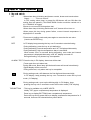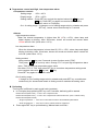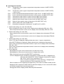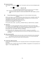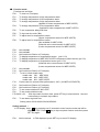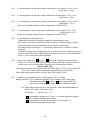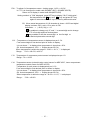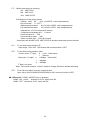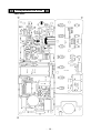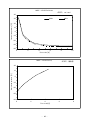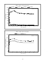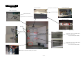
1
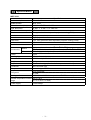
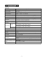
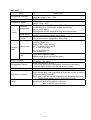
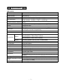
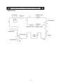
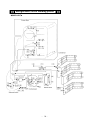
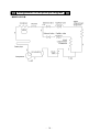
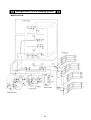
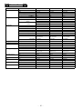
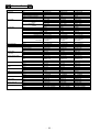
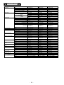
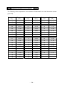
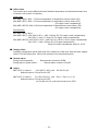
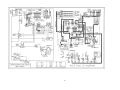
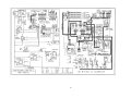
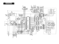
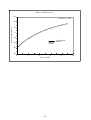
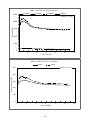
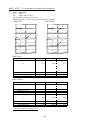
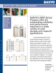
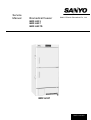
Service
Manual
Biomedical freezer
SANYO Electric Biomedical Co., Ltd.
MDF-U333
MDF-U537
MDF-U537D
MDF-U537
SM7210139
Effective models
This service manual is effective following models.
Model name Model code
MDF-U537 823 168 51
823 168 52
823 168 53
823 168 54
823 168 55
823 168 56
823 168 57
824 168 58
824 168 59
824 168 60
825 168 61
825 168 62
Voltage
115V
220V
220V
230V
240V
115V
110V
230V
220V
240V
MDF-U537D 823
823
823
823
827
823
823
823
823
823
823
823
169
169
169
169
169
169
169
169
169
169
169
169
51
52
53
54
55
56
57
58
59
60
61
62
115V
220V
220V
230V
240V
240V
230V
115V
110V
220V
60Hz
50Hz
60Hz
50Hz
50Hz
50Hz
50Hz
60Hz
60Hz
50Hz
MDF-U333
170
170
170
170
170
170
170
170
170
170
170
170
51
52
53
54
55
56
57
58
59
60
61
62
115V
220V
220V
230V
240V
110V
230V
240V
220V
60Hz
50Hz
60Hz
50Hz
50Hz
60Hz
50Hz
50Hz
50Hz
823
823
823
823
823
823
823
823
823
823
823
823
and Frequency
60Hz
50Hz
60Hz
50Hz
50Hz
60Hz
60Hz
50Hz
50Hz
50Hz
Contents
・Feature
・Specification
・Dimensions
1
MDF-U333
3
MDF-U537
5
MDF-U537D
7
MDF-U333
9
MDF-U537
10
MDF-U537D
11
・Refrigeration circuit
12
Refrigeration circuit principle diagram MDF-U333
15
Refrigeration circuit welding points MDF-U333
16
Refrigeration circuit principle diagram MDF-U537
17
Refrigeration circuit welding points MDF-U537
18
Refrigeration circuit principle diagram MDF-U537D
19
Refrigeration circuit welding points MDF-U537D
20
・Electrical Parts
21
・Specification of sensor
24
・Control specification
25
・W iring diagram
34
・Circuit diagram
37
・Components on P.C.B.
38
・Test data
39
・Parts loyout
49
・User’smanual
50
Features
<MDF-U333>
■ HFC refrigerant
Refrigerant circuit contains HFC refrigerant that effect to environment little.
Latest cooling system reduces negative factor to global environment. With ambient
temperature at 35℃, while temperature of inside chamber maintains -30℃.
■ PCM structure
PCM structure reduces amount of organic solvent.
■ Temperature control function
Unified temperature control range for same categories realized to set -20℃, which
is suitable for reagent preservation.
■ Specification unified
Unified specification for same categories, which also realized to unify performance for
high/low temperature alarm (SV is changeable in the range ±5~±15℃), power failure
alarm, remote alarm terminal, setting memorization by non-volatile memory.
Adopt new microprocessor system for display panel and keypad makes operation easily.
■ Self diagnosis function
Abnormal condition for temperature sensor is indicated by self-diagnosis system.
■ Validation
Control panel enables zero “0” adjust for validation.
■ New door latch mechanism
New door latch is adopted in order to close door surely for reagents.
It is also available to use individual lock mechanism.
■ Insulation wall thickness
Unit has necessary insulation performance for each temperature range.
Combination of PCM and frame form makes 610mm for frame size commonly.
■ Option
Internal temperature observation system is option.
Unit has communication function corresponding to it.
− 1 −
Features
<MDF-U537,537D>
■ HFC refrigerant
Refrigerant circuit contains HFC refrigerant that effect to environment little.
Latest cooling system reduces negative factor to global environment. With ambient
temperature at 35℃, while temperature of inside chamber maintains -30℃.
■ PCM structure
PCM structure reduces amount of organic solvent.
■ Temperature control function
New cooling system realizes to set -20℃, which is suitable for reagent preservation.
■ Specification unified
Unified specification for same categories, which also realized to unify performance for
high/low temperature alarm (SV is changeable in the range ±5~±15℃), power failure
alarm, remote alarm terminal, setting memorization by non-volatile memory.
Adopt new microprocessor system for display panel and keypad makes operation easily.
■ Self diagnosis function
Abnormal condition for temperature sensor is indicated by self-diagnosis system.
■ Validation
Control panel enables zero “0” adjust for validation.
■ New door latch mechanism
New door latch is adopted in order to close door surely for reagents.
It is also available to use individual lock mechanism.
■ Draw box for reagent preservation
100mm for depth of box makes things easily to arrange and take in & out.
(Adopted in bottom chamber of MDF-U537/U537D)
■ Compressor protection function
Sensor detects compressor’s warming up to control unit running.
− 2 −
Specification
MDF-U333
Items
Specification
Model description
Biomedical freezer
Model Number
MDF-U333
Outer dimension (Max)
W 614 × D 733 × H 1620 mm
Inner dimension
W 490 × D 485 × H 1290 mm
Effective chamber capacity
274 lit.
Exterior
Zinc galvanized steel w/powder polyester coating (PCM)
Interior
Polystyrene resin
Insulation
Rigid polyurethane foam
Outer door
1 pc, Zinc galvanized steel w/powder polyester coating (PCM)
Latch
1 pc
Door lock
1 pc
(L) 4 pcs Inner dimension: W 446×D369×H220 mm
(S) 1 pc (for bottom column) Inner dimension: W 487×D221×H155mm
Defrosting spatula 1 pc, key 1 set, 4 card holders
Accessories
Basket
Others
Caster
4 pcs
Leveling legs
2 pcs (with caster)
Access hole
φ 30mm. 1 place in left side.
Weights
81 Kg
Evaporator
Tube on sheet type (function both evaporator and shelf)
Condenser
Wire and tube type
Compressor
Hermetic type 225W
Refrigerant
Cooling performance
HFC refrigerant
R-134a
-30℃ (internal 1/2h air temperature, AT:35℃, no load)
Internal temperature control -20℃~-30℃
range
(AT:5℃~35℃、no load)
Power supply
Local voltage
− 3 −
MDF-U333
Items
Specification
Microprocessor controlled system with non-volatilized memory.
Temperature controller
Temp. set range : -18℃~-40℃
Temperature sensor
Thermistor
LED digital display (green colored) by 1℃.
Temperature display
Range : -50℃~50℃
Changeable SV±5℃~15℃. (Initial SV±10℃)
High/Low
ALARM lamp brinks and buzzer sounds intermittently
Temperature
(about 15 min. delay)
Remote alarm contact: turns ON during power failure alarm.
Alarm
ALARM lamp brinks, buzzer sounds intermittently, remote alarm
Power failure
contact turns ON during power failure alarm.
Remote alarm Remote alarm terminal 3P: contact capacity DC30v, Max2A, N.O.
contact
–COM. (During power failure, temperature alarm: ON)
ALARM lamp
BUZZER: Buzzer key
ALARM TEST: Alarm test key
SET: To switch the SV and PV
Control panel
Operation
>: To shift the set digit
panel
∧: To change the SV
DEF: Defrost key
Rear
Key lock function
Self diagnosis function
Power switch
Compressor protection
Option
Power switch (Breaker switch)
Battery switch: Power failure alarm switch
Press > key for five seconds
L0: Unlock
L1: Lock
When each sensor is in fault,
Error code and internal temperature are displayed alternately.
Remote alarm contact turns ON with buzzer sounds.
Breaker switch
Overload relay
Chart recorder: MTR-G85
Mounting kit: MPR-S7(for bottom mounting)
: MDF-S740T(for top mounting)
− 4 −
Specification
MDF-U537
Items
Specification
Model description
Biomedical freezer
Model Number
MDF-U537
Outer dimension (Max)
W 804 × D 772 × H 1802 mm
Inner dimension
W 658 × D 607 × H 1272 mm
Effective chamber capacity
482 lit.
Exterior
Zinc galvanized steel w/powder polyester coating (PCM)
Interior
Polystyrene resin
Insulation
Rigid polyurethane foam
Zinc galvanized steel w/powder polyester coating (PCM)
2 pcs (upper and lower compartment)
2 pcs
Outer door
Latch
Door lock
Accessories
Basket
Others
1 pc
(M) 6 pcs (upper compartment)
Inner dimension: W 290×D536×H136 mm
(S) 8 pcs (lower compartment)
Inner dimension: W 290×D536×H100mm
Defrosting spatula 1 pc, key 1 set, 14 card holders
Caster
4 pcs
Leveling legs
2 pcs (with caster)
Access hole
φ 30mm. 1 place on rear.
Weights
131 Kg
Evaporator
Tube on sheet type (function both evaporator and shelf)
Condenser
Wire and tube type
Compressor
Hermetic type 350W
Refrigerant
Cooling performance
HFC refrigerant
R-407D
-30℃ (internal 1/2h air temperature, AT:35℃, no load)
Internal temperature control -20℃~-30℃
range
(AT:5℃~35℃、no load)
Power supply
Local voltage
− 5 −
MDF-U537
Items
Specification
Microprocessor controlled system with non-volatilized memory.
Temperature controller
Temp. set range : -18℃~-40℃
Temperature sensor
Thermistor 2P
LED digital display (green colored) by 1℃.
Temperature display
Range : -50℃~50℃
Changeable SV±5℃~15℃. (Initial SV±10℃)
High/Low
ALARM lamp brinks and buzzer sounds intermittently
Temperature
(about 15 min. delay)
Remote alarm contact: turns ON during power failure alarm.
Alarm
ALARM lamp brinks, buzzer sounds intermittently, remote alarm
Power failure
contact turns ON during power failure alarm.
Remote alarm Remote alarm terminal 3P: contact capacity DC30v, 2A, N.O. –COM.
contact
(During power failure, temperature alarm: ON)
ALARM lamp
BUZZER: Buzzer key
ALARM TEST: Alarm test key
SET: To switch the SV and PV
Control panel
Operation
>: To shift the set digit
panel
∧: To change the SV
DEF: Defrost key
Rear
Key lock function
Self diagnosis function
Power switch
Compressor protection
Option
Power switch (Breaker switch)
Battery switch: Power failure alarm switch
Press > key for five seconds
L0: Unlock
L1: Lock
When each sensor is in fault,
Error code and internal temperature are displayed alternately.
Remote alarm contact turns ON with buzzer sounds.
Breaker switch
Overload relay
Detect temperature near compressor by thermistor sensor to control
compressor during overload.
Alarm: Error code and internal temperature are displayed alternately.
Remote alarm contact turns on with buzzer sounds.
Chart recorder: MTR-G85
Mounting kit: MPR-S7(for bottom mounting)
: MDF-S740T(for top mounting)
− 6 −
Specification
MDF-U537D
Items
Specification
Model description
Biomedical freezer
Model Number
MDF-U537D
Outer dimension (Max)
Effective chamber capacity
W 804 × D 772 × H 1802 mm
Upper chamber W 658 × D 607 × H 589 mm
Lower chamber W 658 × D 607 × H 603 mm
452 lit.
Exterior
Zinc galvanized steel w/powder polyester coating (PCM)
Interior
Polystyrene resin
Insulation
Rigid polyurethane foam
Zinc galvanized steel w/powder polyester coating (PCM)
2 pcs (upper and lower compartment)
2 pcs
Inner dimension
Outer door
Latch
Door lock
Accessories
Basket
Others
1 pc
(M) 6 pcs (upper compartment)
Inner dimension: W 290×D536×H136 mm
(S) 8 pcs (lower compartment)
Inner dimension: W 290×D536×H100mm
Defrosting spatula 1 pc, key 1 set, 14 card holders
Caster
4 pcs
Leveling legs
2 pcs (with caster)
Access hole
φ 30mm. 2 places on rear.
Weights
136 Kg
Evaporator
Tube on sheet type (function both evaporator and shelf)
Condenser
Wire and tube type
Compressor
Hermetic type 350W
Refrigerant
Cooling performance
HFC refrigerant
R-407D
-30℃ (internal 1/2h air temperature, AT:35℃, no load)
Internal temperature control -20℃~-30℃
range
(AT:5℃~35℃、no load)
Power supply
Local voltage
− 7 −
MDF-U537D
Items
Specification
Microprocessor controlled system with non-volatilized memory.
Temperature controller
Temp. set range : -18℃~-40℃
Temperature sensor
Thermistor 2P (upper and lower compartment)
LED digital display (green colored) by 1℃.
Range : -50℃~50℃
Temperature display
Selectable to display upper or lower compartment by switch.
Changeable SV±5℃~15℃. (Initial SV±10℃)
High/Low
ALARM lamp brinks and buzzer sounds intermittently
Temperature
(about 15 min. delay)
Remote alarm contact: turns ON during power failure alarm.
Alarm
ALARM lamp brinks, buzzer sounds intermittently, remote alarm
Power failure
contact turns ON during power failure alarm.
Remote alarm Remote alarm terminal 3P: contact capacity DC30v, 2A, N.O. –COM.
contact
(During power failure, temperature alarm: ON)
ALARM lamp
BUZZER: Buzzer key
ALARM TEST: Alarm test key
SET: To switch the SV and PV
Control panel
>: To shift the set digit
Operation
∧: To change the SV
panel
DEF: Defrost key
TOP/BOTTOM: Switch key to display upper or lower compartment.
Rear
Key lock function
Self diagnosis function
Power switch
Compressor protection
Option
Power switch (Breaker switch)
Battery switch: Power failure alarm switch
Press > key for five seconds
L0: Unlock
L1: Lock
When each sensor is in fault,
Error code and internal temperature are displayed alternately.
Remote alarm contact turns ON with buzzer sounds.
Breaker switch
Overload relay
Detect temperature near compressor by thermistor sensor to control
compressor during overload.
Alarm: Error code and internal temperature are displayed alternately.
Remote alarm contact turns on with buzzer sounds.
Chart recorder: MTR-G85
Mounting kit: MPR-S7(for bottom mounting)
: MDF-S740T(for top mounting)
− 8 −
Dimensions
<MDF-U333>
>
− 9 −
Dimensions
<MDF-U537>
>
− 10 −
Dimensions
<MDF-U537D>
>
− 11 −
Refrigeration circuit
MDF-U333
Unit:mm
Parts description
Evaporator
Dehydrator
Capillary tube
Condenser assembly A
Condenser assembly B
Specification
Type
Material
Type of molecular sieves
Charged q’ty
Resistance
Dimension
Resistance indicator color
Type
Dimension
Type
Dimension
Frame pipe
Tube on sheet
Aluminum (φ 8.0)
4A-XH9(134 stamped)
8±1g
0.686MPaG (7Kgf/㎠ G)
φ 1.8×(φ 0.65)×2000mm
White
Wire and tube
w
480×P40×30 columns
Wire and tube
w
480×P40×30 columns
Note: Lower 2 columns are used
in desuper circuit.
Material
C1220T-1/2H
Dimension
φ 4.0×t0.5
Evacuation and vacuum Evacuation time: over than 20min. by 2 ports (high pressure and low
pressure
pressure side). (N2 exchange)
When charged, vacuum pressure is lower than 1.0torr
(pump capacity: 300L/min)
Refrigerant and oil
Refrigerant : R-134a
Charged q’ty : 226±5g
Oil : CF-32
Charged q’ty : 230±10cc
Oil additive: n-pentane
Charged q’ty : 14g
Refrigeration circuit spec.
Refer to following pages
and welding points
− 12 −
Refrigeration circuit
MDF-U537
Unit:mm
Parts description
Evaporator
Upper (1)
Lower (1)
Bottom (3)
Dry core
Specification
Type
9lines×1column×5pcs
Material
Aluminum (φ 8.0)
Type
D-S032T
Manufacturer
SANYO
Solid core
50cm3
Capillary tube
Resistance
0.725MPaG (7.4Kgf/㎠ G)
(Total number: 2)
Dimension
φ 1.8×L4500
Resistance indicator color
Blue
Condenser
assembly Type
Wire and tube
w
front (Total number: 4)
480×P40×6 columns
Dimension
Frame pipe
Material
C1220T
Dimension
φ 4.0×t0.5×L7470
Evacuation and vacuum Evacuation time: over than 20min. by 2 ports (high pressure and low
pressure
pressure side). (N2 exchange)
When charged, vacuum pressure is lower than 1.0torr
(pump capacity: 300L/min)
Refrigerant and oil
Refrigerant : R-407D
Charged q’ty : 301±5g
Oil : CF-32
Charged q’ty : 280±10cc
Oil additive: n-pentane
Charged q’ty: 19g
Refrigeration circuit spec.
Refer to following pages
and welding points
− 13 −
Refrigeration circuit
MDF-U537D
Unit:mm
Parts description
Evaporator assembly
Upper (1)
Lower (1)
Bottom (2)
Lower entrance (1)
Dry core
Specification
Type
9lines×1column×5pcs
Material
Aluminum (φ 8.0)
Type
Manufacturer
Solid core
D-S032T
SANYO
50cm3
Upper compartmnt Lower compartmnt
10.3Kg/㎠ G
9.9Kg/㎠ G
L
φ 1.8× 4000
φ 1.8×L3000
Yellow
Red
Wire and tube
w
480×P40×6 columns
C1220T
Capillary tube
Resistance
Dimension
Resistance indicator color
Condenser
assembly Type
front (Total number: 4)
Dimension
Frame pipe
Material
Dimension
φ 4.0×t0.5×L7470
Evacuation and vacuum Evacuation time: over than 20min. by 2 ports (high pressure and low
pressure
pressure side). (N2 exchange)
When charged, vacuum pressure is lower than 1.0torr
(pump capacity: 300L/min)
Refrigerant and oil
Refrigerant : R-407D
Charged q’ty : 357±5g
Oil : CF-32
Charged q’ty : 280±10cc
Oil additive: n-pentane
Charged q’ty : 23g
Refrigeration circuit spec.
Refer to following pages
and welding points
− 14 −
Refrigeration circuit principle diagram
<MDF-U333>
>
− 15 −
Refrigeration circuit welding points
<MDF-U333>
>
− 16 −
Refrigeration circuit principle diagram
<MDF-U537>
>
− 17 −
Refrigeration circuit welding points
<MDF-U537>
>
− 18 −
Refrigeration circuit principle diagram
<MDF-U537D>
>
− 19 −
Refrigeration circuit welding points
<MDF-U537D>
>
− 20 −
Electrical Parts
MDF-U333
Compressor
AC110V,60Hz
C-2SN220L2W
C-2SN220L5W
Code
80771120
80771122
80771125
Rated voltage (50/60Hz)
100 / 100 , 110
-- / 115
220,240 / 220
Winding resistance C-S(Aux)
5.8Ω
7.2Ω
30.6Ω
1.6Ω
2.0Ω
7.8Ω
AMVL-180A
AMVL-180A
AMVL-300A
Type
Pick up voltage(50Hz)
(60Hz)
Drop out voltage(50Hz)
AC91V∼111V
AC91V∼111V
AC185V∼217V
AC108∼128V
AC108∼128V
AC215∼232V
AC60∼120V
AC30∼65V
AC30∼65V
AC30∼75V
AC30∼75V
AC69∼132V
P24KU
P19KU
P10MU
OFF 150±10℃
150±10℃
130±8℃
ON 85±10℃
85±10℃
69±10℃
19.5A
10A
6~15 seconds
6~15 seconds
5.4A more than
30 minutes
2.5A more than
30 minutes
(60Hz)
Overload relay
AC220-240V , 50/60Hz
C-2SN220L0W
C-R(Main)
Starting relay
AC115V,60Hz
Type
Type
Action to the temp. (No current)
Action to the current (AT25℃)
24.0A
Operation time 6~15 seconds
Non-Action to the temp. (80℃)
6.1A more than
Non-Action 30 minutes
Action 8.0A within 15 minutes
7.4A within 15 minutes
3.4A within 15 minutes
100μF,160VAC
30μF,300VAC
Starting capacitor
Rating
100μF,160VAC
Running capacitor
Temp. control relay
Rating
25μF,220VAC
20μF,220VAC
5μF,400VAC
Type
G4F-11123T
G4F-11123T
G4F-11123T
Switching power supply
Contact capacity
AC220V,20A
AC220V,20A
AC220V,20A
Coil
DC12V
DC12V
DC12V
Type
ZWS10-12/J
AC100-240V
50/60Hz,0.3A
ZWS10-12/J
AC100-240V
50/60Hz,0.3A
ZWS10-12/J
AC100-240V
50/60Hz,0.3A
Input
Temperature sensor
Rated output
DC12V,0.85A
DC12V,0.85A
DC12V,0.85A
Type
502AT-1
502AT-1
502AT-1
Rating
5kΩ,25℃
5kΩ,25℃
5kΩ,25℃
P.C.B.
Type
DF-333
DF-333
DF-333
Battery
Type
5HR-AAC
5HR-AAC
5HR-AAC
Rating
6V 1100MAH
6V 1100MAH
6V 1100MAH
Type
SLE6A2-5
SLE6A2-5
SLE6A2-5
Battery switch
Breaker switch
Rating
AC250V 4A
AC250V 4A
AC250V 4A
Type
BAM215131
BAM215131
BAM215131
Rating
AC250V 15A
AC250V 15A
AC250V 15A
− 21 −
Electrical Parts
MDF-U537
Compressor
Starting relay
Overload relay
Starting capacitor
Running capacitor
Temp. control relay
Solenoid valve
control relay
Switching power supply
Type
Code
Rated voltage (50/60Hz)
Winding resistance C-S(Aux)
C-R(Main)
Type
Pick up voltage(50Hz)
(60Hz)
Drop out voltage(50Hz)
(60Hz)
Type
Action to the temp. (No current)
OFF
ON
Action to the current (AT25℃)
Operation time
Non-Action to the temp. (80℃)
Rating
Rating
Type
Contact capacity
Coil
Type
Contact capacity
Coil
Type
Input
Rated output
Type
Rating
Solenoid valve control
Type
sensor
Rating
Compressor protect sensor Type
Rating
P.C.B.
Type
Battery
Type
Rating
Battery switch
Type
Rating
Breaker switch
Type
Rating
Solenoid valve coil
Type
Rating
Type
Condensing fan motor
Rating
Thermal fuse
Temperature sensor
AC110-115V,60Hz
C-2SN350L0R
807764201
AC220V,50/60Hz
C-2SN350L5S
807763251
AC230V-240V,50Hz
C-2SN350L5S
807763251
5.8Ω
1.6Ω
AMVL-180A
AC91V∼111V
AC108∼128V
AC30∼65V
AC30∼75V
P18AU
30.6Ω
7.8Ω
AMVL-300A
AC185V∼217V
AC215∼232V
AC60∼120V
AC69∼132V
P10MU
30.6Ω
7.8Ω
AMVL-300A
AC185V∼217V
AC215∼232V
AC60∼120V
AC69∼132V
P10MU
120±8℃
69±10℃
18.5A
6~15 seconds
130±8℃
69±10℃
10A
6~15 seconds
130±8℃
69±10℃
10A
6~15 seconds
2.5A more than
30 minutes
3.4A within 15 minutes
30μF,300VAC
5μF,400VAC
G4F-11123T
AC220V,20A
DC12V
G2R-1A-T
AC250V,10A
DC12V
ZWS10-12/J
AC100-240V
50/60Hz,0.3A
DC12V,0.85A
502AT-1
5kΩ,25℃
502AT-1
5kΩ,25℃
502AT-1
5kΩ,25℃
DF-537
5HR-AAC
6V 1100MAH
SLE6A2-5
AC250V 4A
BAM215131
AC250V 15A
NEVAC220V
220V 50/60Hz
FU2-A051B5MP
220-240V 50/60Hz
130℃
2.5A more than
30 minutes
3.4A within 15 minutes
30μF,300VAC
5μF,400VAC
G4F-11123T
AC220V,20A
DC12V
G2R-1A-T
AC250V,10A
DC12V
ZWS10-12/J
AC100-240V
50/60Hz,0.3A
DC12V,0.85A
502AT-1
5kΩ,25℃
502AT-1
5kΩ,25℃
502AT-1
5kΩ,25℃
DF-537
5HR-AAC
6V 1100MAH
SLE6A2-5
AC250V 4A
BAM215131
AC250V 15A
NEVAC240V
240V 50/60Hz
FU2-A051B5MP
220-240V 50/60Hz
130℃
4.0A more than
Non-Action 30 minutes
Action 5.5A within 15 minutes
100μF,160VAC
25μF,220VAC
G4F-11123T
AC220V,20A
DC12V
G2R-1A-T
AC250V,10A
DC12V
ZWS10-12/J
AC100-240V
50/60Hz,0.3A
DC12V,0.85A
502AT-1
5kΩ,25℃
502AT-1
5kΩ,25℃
502AT-1
5kΩ,25℃
DF-537
5HR-AAC
6V 1100MAH
SLE6A2-5
AC250V 4A
BAM215131
AC250V 15A
NEVAC120V
120V 50/60Hz
FU2-A051B1MP
AC110-115V 50/60Hz
130℃
− 22 −
Electrical Parts
MDF-U537D
Compressor
Starting relay
Overload relay
Starting capacitor
Running capacitor
Compressor relay
Temp. control relay
Switching power supply
Type
Code
Rated voltage (50/60Hz)
Winding resistance C-S(Aux)
C-R(Main)
Type
Pick up voltage(50Hz)
(60Hz)
Drop out voltage(50Hz)
(60Hz)
Type
Action to the temp. (No current)
OFF
ON
Action to the current (AT25℃)
Operation time
Non-Action to the temp. (80℃)
Rating
Rating
Type
Contact capacity
Coil
Type
Contact capacity
Coil
Type
Input
Rated output
Type
Rating
Solenoid valve control
Type
sensor
Rating
Compressor protect sensor Type
Rating
P.C.B.
Type
Battery
Type
Rating
Battery switch
Type
Rating
Breaker switch
Type
Rating
Solenoid valve coil
Type
(2 pcs.)
Rating
Type
Condensing fan motor
Rating
Thermal fuse
Temperature sensor
AC110-115V,60Hz
C-2SN350L0R
807764201
AC220V,50/60Hz
C-2SN350L5S
807763251
AC230V-240V,50Hz
C-2SN350L5S
807763251
5.8Ω
1.6Ω
AMVL-180A
AC91V∼111V
AC108∼128V
AC30∼65V
AC30∼75V
P18AU
30.6Ω
7.8Ω
AMVL-300A
AC185V∼217V
AC215∼232V
AC60∼120V
AC69∼132V
P10MU
30.6Ω
7.8Ω
AMVL-300A
AC185V∼217V
AC215∼232V
AC60∼120V
AC69∼132V
P10MU
120±8℃
69±10℃
18.5A
6~15 seconds
130±8℃
69±10℃
10A
6~15 seconds
130±8℃
69±10℃
10A
6~15 seconds
2.5A more than
30 minutes
3.4A within 15 minutes
30μF,300VAC
5μF,400VAC
G4F-11123T
AC220V,20A
DC12V
G2R-1A-T
AC250V,10A
DC12V
ZWS10-12/J
AC100-240V
50/60Hz,0.3A
DC12V,0.85A
502AT-1
5kΩ,25℃
502AT-1
5kΩ,25℃
502AT-1
5kΩ,25℃
DF-537D
5HR-AAC
6V 1100MAH
SLE6A2-5
AC250V 4A
BAM215131
AC250V 15A
NEVAC220V
220V 50/60Hz
FU2-A051B5MP
220-240V 50/60Hz
130℃
2.5A more than
30 minutes
3.4A within 15 minutes
30μF,300VAC
5μF,400VAC
G4F-11123T
AC220V,20A
DC12V
G2R-1A-T
AC250V,10A
DC12V
ZWS10-12/J
AC100-240V
50/60Hz,0.3A
DC12V,0.85A
502AT-1
5kΩ,25℃
502AT-1
5kΩ,25℃
502AT-1
5kΩ,25℃
DF-537D
5HR-AAC
6V 1100MAH
SLE6A2-5
AC250V 4A
BAM215131
AC250V 15A
NEVAC240V
240V 50/60Hz
FU2-A051B5MP
220-240V 50/60Hz
130℃
4.0A more than
Non-Action 30 minutes
Action 5.5A within 15 minutes
100μF,160VAC
25μF,220VAC
G4F-11123T
AC220V,20A
DC12V
G2R-1A-T
AC250V,10A
DC12V
ZWS10-12/J
AC100-240V
50/60Hz,0.3A
DC12V,0.85A
502AT-1
5kΩ,25℃
502AT-1
5kΩ,25℃
502AT-1
5kΩ,25℃
DF-537D
5HR-AAC
6V 1100MAH
SLE6A2-5
AC250V 4A
BAM215131
AC250V 15A
NEVAC120V
120V 50/60Hz
FU2-A051B1MP
AC110-115V 50/60Hz
130℃
− 23 −
Specifications of sensor
The following show temperature and resistance characteristics on each thermistor sensor
(type 502).
Temperature
(℃)
Resistance
(kΩ )
Temperature
(℃)
Resistance
(kΩ )
Temperature
(℃)
Resistance
(kΩ )
-50
154.50
-7
17.92
12
8.17
-45
116.50
-6
17.16
13
7.85
-40
88.85
-5
16.43
14
7.55
-35
68.15
-4
15.74
15
7.27
-30
52.84
-3
15.08
16
6.99
-25
41.19
-2
14.45
17
6.73
-20
32.43
-1
13.86
18
6.48
-19
30.92
0
13.29
19
6.24
-18
29.50
1
12.74
20
6.01
-17
28.14
2
12.22
25
5.00
-16
26.87
3
11.72
30
4.18
-15
25.65
4
11.25
35
3.51
-14
24.51
5
10.80
40
2.96
-13
23.42
6
10.37
45
2.51
-12
22.39
7
9.96
50
2.14
-11
21.41
8
9.57
55
1.83
-10
20.48
9
9.20
60
1.57
-9
19.58
10
8.84
-8
18.73
11
8.49
− 24 −
Control specification
<MDF-U333・
・537・
・537D>
>
1. Key and switch
BZ
:When alarm lamp is blinking and buzzer sounds, buzzer and remote alarm
Output …………Force to turn off
In F25, setting value (time) is except for 000;buzzer will turn ON after the
setting time has passed. (This RING BACK function would be carried out in
s/n 110XXXXX or bigger)
:Buzzer is not turned off during alarm test.
:When alarm lamp is blinking and buzzer is off, buzzer will not turn on.
:When press this key during power failure, current internal temperature is
displayed for 5 seconds.
SET
:Press once to setting mode and press again to memorize the set value.
(It works as ENTER key)
DEF
:In PV display keep pressing the key over 5 seconds to start defrosting.
During defrosting, press the key to quit defrosting.
During defrosting, internal temperature and “dF” is displayed alternately.
During defrosting, high-low temperature alarm is cancelled.
When sensor error is occurred during defrosting, error code and internal
temperature is displayed alternately, and “dF” display is turned off.
During defrosting, only buzzer key is acceptable.
ALARM TEST:Press the key in PV display, alarm test will be start.
Press again then quit alarm test.
During alarm test, alarm lamp will blink and buzzer will sound intermittently.
Digital display will be turned off.
During alarm test, only alarm test key is acceptable.
:During setting mode, shift between the first digit and the second digit.
In PV display, keep pressing the key over 5 seconds to enter the key lock
mode. (“L0”display)
:During setting mode, count up the blinking digit. In PV display, keep
pressing the key over 5 seconds to enter the function mode (“F00” display)
TOP/BOTTOM
:This key is available only in MDF-U537D.
Initially TOP (upper compartment) temperature is displayed.
Press key to display BOTTOM (lower compartment) temperature.
Press this key during power failure to display compartment temperature for 5
seconds, that was not selected before power failure.
− 25 −
2.Temperature
control and High, Low temperature alarm
2.
<Temperature control>
Setting range : -18℃~-40℃
Display range : -50℃~+50℃
Setting method :Press SET key and set the required value with
key and
Key. Press SET key again to memorize the set value,
And then return to PV display.
Out of setting range : If change to out of setting range value by mistake and press
SET key , buzzer sound continuously for 1 second.
<Alarm>
High temperature alarm :
When the internal temperature is higher than SV (+5℃~+15℃), alarm lamp and
digital display is blinking. After 15min.later, buzzer will sound and remote alarm
contact will turn ON. (initial value: +10℃)
Low temperature alarm :
When the internal temperature is lower than SV(-5℃~-15℃), alarm lamp and digital
display is blinking. After 15min.later, buzzer will sound and remote alarm contact will
turn ON. (initial value: -10℃)
Setting method :
Keep pressing
key over 5 seconds to enter function mode (“F00”).
Then press
key to count up value. Change “F01” to input high temperature alarm
value, “F02” to input low temperature alarm value.
Set either “F01” or “F02” then press SET key to turn alarm temperature setting mode
to set required value with
key and
key.
Press SET key again to memorize value.
Out of setting range :
If change to out of setting range value by mistake and press SET key, sound buzzer
continuously for 1second and remain in setting mode to maintain the setting value.
3. Defrosting
This function is different by each model code (products) .
a. In PV display keep pressing DEF key over 5 seconds, defrosting will be started.
Model code 001 (MDF-U333) --- Force to turn compressor OFF.
Model code 002 (MDF-U537) --- Force to turn compressor & solenoid valve OFF. (Use 1 solenoid valve)
Model code 003 (MDF-U537D)
--- Single compartment → Force to turn OFF solenoid valve at the ROOM lamp illuminated.
--- Both compartments → Force to turn OFF 2 solenoid valves & compressor.
b.
Press again DEF key to quit defrosting.(Manual start and finish)
− 26 −
4. Self diagnosis function
E01 : Temperature sensor (upper compartment temperature sensor for MDF-U537D)
is open circuit
E02 : Temperature sensor (upper compartment temperature sensor for MDF-U537D)
is short circuit
E03 : Lower compartment temperature sensor is open circuit (for MDF-U537D only)
E04 : Lower compartment temperature sensor is short circuit (for MDF-U537D only)
E05 : Compressor protect sensor is open circuit (for MDF-U537,U537D)
E06 : Compressor protect sensor is short circuit (for MDF-U537,U537D)
E07 : Solenoid valve control sensor is open circuit (for MDF-U537 only)
E08 : Solenoid valve control sensor is short circuit (for MDF-U537 only)
E09 : Buttery switch OFF with ALARM TEST
E10 : Compressor temperature is abnormal (for MDF-U537, U537D)
a. Model code setting (for code: 001,002,003)
When temperature sensor is open circuit, display shows alternately E01 with –50℃.
When temperature sensor is short circuit, display shows alternately E02 with +50℃.
b. Model code setting (for code: 002)
When solenoid valve control sensor is open circuit, display shows alternately E07 with
–50℃.
When solenoid valve control sensor is short circuit, display shows alternately E08 with
+50℃.
c. Model code setting (for code: 003)
When TOP lamp is displayed, display shows same as a. in upper compartment.
When BOTTOM lamp is displayed, display shows lower compartment temperature.
When lower compartment temperature sensor is open circuit, display shows alternately
E03 with –50℃.
When lower compartment temperature sensor is short circuit, display shows alternately
E04 with +50℃.
d. Error diagnosis
Self diagnosis of open circuit is done when it is lower than -60℃.
Self diagnosis of short circuit is done when it is higher than +60℃.
E09 is functioned only during ALARM TEST is performed.
In E10 is displayed: When condenser temperature is higher than 85℃, it diagnoses as
abnormal and indicate E10. When condenser temperature is higher
than 100℃ force to turn compressor OFF.
When condenser temperature is lower than 65℃, it diagnoses as
normal and cancel to force compressor turn OFF.
When numbers of error happened simultaneously, error code of smallest number will be
displayed. With exception for MDF-U537D, alternative display of error code and PV,which
is selected compartment internal temperature .
During power failure, display shows alternately E09 with blank.
− 27 −
5. Key lock function
In PV display、Keep pushing
“L0”.
Push
key to
key over 5 seconds to enter key lock mode displaying with
1 ・・・・・key lock ON
0 ・・・・・key lock OFF
then press SET key to memorize set value then return to PV display.
Note) With key lock ON to enter SET mode, but unable to change value.
With key lock ON to perform Function and ALARM TEST, while unable to perform
DEF.
6.
Power failure alarm (Buzzer and display isn’t functioned without buttery power
supplied)
When power failure is occurred, power failure alarm will be turned on by battery inside units.
During power failure alarm, alarm lamp is blinking, digit display turns off, buzzer sounds
intermittently and remote alarm contact turns ON.
Press BZ key to turn power failure alarm buzzer OFF.
Press BZ key to display PV for 5 seconds.
During power failure alarm, only BZ key (TOP/BOTTOM key for MDF-U537D) is available.
7. Alarm test
The function is to check performance (failure) for alarm lamp, buzzer and remote alarm.
In PV display, press ALARM TEST key to blink alarm lamp, to sound buzzer intermittently, to
turn remote alarm contact on (Without time delay). Digital display will be turned off.
During alarm test, only ALARM TEST key is available.
Note: During alarm test, with buttery switch turned OFF to display error code E09.
Displaying error code E09 takes priority over other error codes before ALARM TEST is
performed.
8. Auto return function
Function: During setting mode or key lock mode or function mode with any key not pressed
for 90 seconds, value will not be memorized to return to PV mode automatically.
Note: In F09 or F10, auto return function will not be performed.
9. Compressor delay start time
During cycle time, normally force to turn compressor OFF after 2 minutes passed compressor
turned off.
When main power is supplied (microcomputer is RESET), changeable to set compressor time
lag for 1 ~15 minutes. (See F05)
− 28 −
10.Function
mode
10.
Functions are as follow.
F00 : To return to PV display
F01 : To change temperature of high temperature alarm
F02 : To change temperature of low temperature alarm
F03 : To change temperature of high temperature alarm
(Applied for lower compartment of MDF-U537D)
F04 : To change temperature of low temperature alarm
(Applied for lower compartment of MDF-U537D)
F05 : To set compressor delay start time
F06 : To input service code (384)
F07 : To adjust zero for temperature sensor
(Upper compartment sensor for MDF-U537D)
F08 : To adjust zero for temperature sensor
(Not available for MDF-U333)
(Solenoid valve control sensor for MDF-U537)
(Lower compartment sensor for MDF-U537D)
F09 : Not available
F10 : Not available
F11 : Not functioned. Return to PV display.
F12 : To display temperature of temperature sensor (per 0.1℃)
F13 : To display temperature of MDF-U537/U537D compressor protect sensor (per 1℃)
F14 : To display temperature of temperature sensor (per 0.1℃)
(Solenoid valve control sensor for MDF-U537)
(Lower compartment sensor for MDF-U537D)
F15 : Not available
F16 : Not functioned. Return to PV display.
F17 : To set or check model code
model code 001: MDF-U333
model code 002: MDF-U537
model code 003: MDF-U537D
F18 : Preset value for second offset performance: -26℃ (for MDF-U537/U537D)
F19 : Not functioned. Return to PV display.
F20 : Not functioned. Return to PV display.
F21 : To set communication ID(000~255)
F22 : To set communication mode
F23,24,26~29 : With input each function code, press SET key to sound buzzer 1 second
continuously to maintain input status.
F25 : To set alarm ring back time
Setting value: 000,010,020,030,040,050,060
Setting method :
In PV display, keep
key pressing over 5 seconds to enter function mode and will be
displayed “F00”. Press
key to input required function code then press
SET key again.
F00 : Not functioned.
In F00 displayed, press SET key to return PV display.
− 29 −
F01 : To set temperature of high temp. alarm performance in the range of +5℃~+15℃.
(initial value : +10℃)
F02 : To set temperature of low temp. alarm performance in the range of -5℃~-15℃.
(initial value : -10℃)
F03 : To set temperature of high temp. alarm performance in the range of +5℃~+15℃.
(initial value : +10℃)
Return to PV display except for lower compartment of MDF-U537D.
F04 : To set temperature of low temp. alarm performance in the range of -5℃~-15℃.
(initial value : -10℃)
Return to PV display except for lower compartment of MDF-U537D.
F05 : To set compressor delay start time
(performed only when main power supplied or microcomputer reset)
The function is to reduce compressor’s start up failure or breaker’s blown out that
caused by numbers of units simultaneous start up after power failure.
The setting range of time lag is 1~15 minutes. (Initial value is 1 minute on factory
outgoing)
SV before doing factory’s performance test, is 3 seconds or less. Therefore, the time
lag is 0 (3 seconds) when PCB replacement is done in service. It is recommended to
input 1~15 for value when PCB is replaced.
F06 : Input service code with
key and
key when F07 and following functions,
except F21, F22 and F25 would be performed. Press SET key to memorize service
code to enter function mode again to perform F07 and following functions.
Service code : 384
Note)Service code is memorized unless input “000” again in ”F06”, or turn power OFF.
(Turn OFF = buttery switch and power supply switch are turned OFF)
Note) After using service code on service, input “000” again in “F06”.
F07 :To adjust 0 of temperature sensor (setting range: -9.9℃~+9.9℃)
Setting method: In ”F07” displayed, press SET key to display ”00.0”(initial value).
Set temperature with
key and
key and press SET key
again to memorize set value. Input is done by differential value.
Ex) When actual temperature of 1/2h is shown –28.5℃and digital display is
shown -30℃, add +1.5 to value in F07.
Calculation = (-28.5-(-30)) = +1.5
key enables to change only “0” and “-“ in second digit and to change
“0”~”9” in first digit and first decimal place.
key enables to shift the second digit ⇔ the first digit ⇔
the first decimal place⇔the second digit.
− 30 −
F08 :To adjust 0 of temperature sensor (setting range: -9.9℃~+9.9℃)
In F17: It is functioned in model code 002(MDF-U537), 003(MDF-U537D).
Return to PV display in model code 001(MDF-U333)
Setting method: In ”F08” displayed, press SET key to display ”00.0”(initial value).
Set temperature with
key and
key and press SET key
again to memorize set value. Input is done by differential value.
Ex) When actual temperature of 1/2h chamber is shown –28.5℃and digital
display is shown -30℃, add +1.5 to value in F08.
Calculation = (-28.5-(-30)) = +1.5
key enables to change only “0” and “-“ in second digit and to change
“0”~”9” in first digit and first decimal place.
key enables to shift the second digit ⇔ the first digit ⇔
the first decimal place⇔the second digit.
F12 :Temperature of temperature sensor is displayed as per 0.1℃.
From second digit to first decimal point is shown in display.
It is not shown “-“ in display when temperature is lower than -20℃.
(Ex. Actual temperature -35℃ → Display shows 35.0℃)
When temperature is within the range of -19.9℃~-0.1℃, ”-“ is displayed.
Range : -72.0~+83.0℃(±9.9℃)
F13 :Temperature of compressor protect sensor is displayed as per 1℃.
Range: -72~+163℃
F14 :Temperature sensor (solenoid valve control sensor for MDF-U537, lower compartment
temperature control sensor for MDF-U537D)
Temperature of each sensor is displayed as per 0.1℃
From second digit to first decimal point is shown in display.
It is not shown “-“ in display when temperature is lower than -20℃.
(Ex. Actual temperature -35℃ → Display shows 35.0℃)
When temperature is within the range of -19.9℃~-0.1℃, ”-“ is displayed.
Range : -72.0~+83.0℃
− 31 −
F17 :Model code setting or checking
001 :MDF-U333
002 :MDF-U537
002 :MDF-U537D
Followings are initial setting values
Internal temp. SV : -30℃ (for U537D : both compartments)
Key lock mode : 0 (OFF)
High temperature alarm : SV+10℃(for U537D : both compartments)
Low temperature alarm : SV-10℃(for U537D : both compartments)
0 adjustment:+0℃(for temperature sensor)
Compressor start delay time : 1 minute
Communication ID : 000
Communication mode : 000
Alarm ring back time : 030 (30 minutes)
Set model code as MDF-U537, MDF-U537D to activate compressor protect function.
F21 : To set serial communication ID.
Input range: 000~255 (000 means that communication is OFF)
F22 : To set serial communication mode.
0 : Local (initial value)
Control mode (3rd digit)
1 : Remote
nd
Baud rate (2 digit) 0 : 2400bps (initial value)
1 : 4800bps
2 : 9600bps
st
1 digit is not used.
Note) Set control mode as “remote” unable to change SV and to activate defrosting.
F25 : To set value for alarm recovery (ring back) time.
Input value: 000,010,020,030,040,050,060 (In 000, recovery function is OFF)
11.Differential
(COMP. ON/OFF point on program)
11.
COMP ON permit : Activate at +0.0℃ higher than SV
COMP OFF: Activate at -0.6℃ lower than SV
− 32 −
12.Offset
value
12.
The function is to correct differential value between temperature of temperature sensor and
of internal 1/2H (centre of chamber).
Initial offset
001 (MDF-U333): Shift –1.5℃from temperature of temperature control sensor (PV)
002 (MDF-U537): Shift +1.0℃from temperature of temperature control sensor (PV)
(For upper, lower compartment)
003 (MDF-U537D): Shift +0.0℃from temperature of temperature control sensor (PV)
(For upper, lower compartment)
Second offset
001 (MDF-U333): None
002 (MDF-U537):-18℃≧SV≧-25℃--- shift –0℃from PV (For upper, lower compartment)
-26℃≧SV -- shift +1.0 from PV (For upper, lower compartment)
003 (MDF-U537D):-18℃≧SV≧-30℃--- shift PV-2.4+(-18-SV)÷5 (For upper compartment)
-30℃>SV --- shift –0℃from PV (For upper compartment)
*Note) For lower compartment, add 0℃ to PV.
13.Display
offset
13.
In display, temperature that is lower than SV is shown for a little time. With this case, display
offset –0.5℃should be done. (Round off numbers to the first decimal point)
14.Remote
alarm
14.
During normal operation … … … Remote alarm contact is OPEN
During alarm or power failure … … … Remote alarm contact is CLOSE
15.Others
15.
MDF-U537: In case of : -18℃≧SV≧–25℃ with PV-SV+5℃≧0
Solenoid valve is: Forced to turn OFF
MDF-U537: In case of : PV-(SV-0.6℃)≧0 with PVTOP - PVBOTTOM -1>0
Solenoid valve is: Forced to turn OFF
(In PV-(SV-0.6)<0, quit to be forced to turn OFF)
− 33 −
Wiring diagram
− 34 −
− 35 −
− 36 −
Circuit diagram
<Main PCB>
− 37 −
Components on PCB
<Main PCB>
− 38 −
Test data
・MDF-U333 Pull down
・MDF-U333 Pull up
・MDF-U333 Cooling unit pressure
・MDF-U333 Power consumption
・MDF-U333 Temperature uniformity and fluctuation
・MDF-U537 Pull down
・MDF-U537 Pull up
・MDF-U537 Cooling unit pressure
・MDF-U537 Power consumption
・MDF-U537D Pull down
・MDF-U537D Pull down
・MDF-U537D Pull up
・MDF-U537D Cooling unit pressure
・MDF-U537D Power consumption
・MDF-U537/D Temperature uniformity and fluctuation
− 39 −
40
40
41
41
42
43
43
44
44
45
45
46
47
47
48
MDF-U333 Pull down
AT35℃,no load
40
50Hz
Internal temperature [℃]
30
60Hz
20
10
0
-10
-20
-30
-40
0
2
4
6
8
10
Time scale [H]
MDF-U333 Pull up
AT35℃,無負荷
20
Internal temperature [℃]
10
0
-10
-20
-30
-40
0
2
4
Time scale[H]
− 40 −
6
8
MDF-U333 Cooling unit pressure
Pd(50Hz)
Ps(50Hz)
Pd(60Hz)
Ps(60Hz)
1600
AT35℃,no load
1400
Pressure [kPa]
1200
1000
800
600
400
200
0
0
1
2
3
4
Time scale [h]
5
6
7
MDF-U333 Power consumption
W(50Hz)
W(60Hz)
250
AT35℃,no load
Power consumption[W]
200
150
100
50
0
0
1
2
3
4
Time scale [h]
− 41 −
5
6
7
MDF-U333
Temperature uniformity and fluctuation
(Test condition)
Mains
: 1φ100V50/60Hz
AT
: 35℃
SV
: -25℃・-20℃・-30℃
No load Measure with type T sensor
Measuring point:Center point of each container
1
2
3
4
5
(1).SV=-25℃
Measuring point
Top
1
2
3( 1/2 center air)
Middle
4
Bottom
5
Uniformity
Max./Min
Range(deg)
Temperature(℃) Fluctuation(℃)
-21.8
-23.2
-24.3
± 2.0
-24.6
-24.2
-21.8/-24.6
2.8(±1.4)
(2).SV=-20℃
Measuring point
Top
1
2
3( 1/2 center air)
Middle
4
Bottom
5
Uniformity
Max./Min
Range(deg)
Temperature(℃) Fluctuation(℃)
-17.1
-18.3
-19.1
± 2.6
-19.4
-19.0
-17.1/-19.4
2.3(±1.15)
(3).SV=-30℃
Measuring point
1
2
3( 1/2 center air)
Middle
4
Bottom
5
Uniformity
Max./Min
Range(deg)
Top
Temperature(℃) Fluctuation(℃)
-26.3
-28.1
-29.3
± 1.7
-29.4
-29.1
-26.3/-29.4
3.2(±1.6)
note)These data are reference only.
− 42 −
MDF-U537 Pull down
50Hz
60Hz
AT 35℃,no load
40
Internal temperature[℃]
30
20
10
0
-10
-20
-30
-40
0
2
4
6
Time scale [H]
8
10
12
MDF-U537 Pull up
AT 35℃,no load
20
Internal temperature [℃]
10
0
-10
-20
-30
-40
0
2
4
6
Time scale [H]
− 43 −
8
10
MDF-U537Cooling unit pressure
Pd(60Hz)
Ps(50Hz)
Pd(60Hz)
Ps(60Hz)
2000
AT 35℃,no load
Pressure [kPa]
1500
1000
500
0
0
2
4
6
Time scale [H]
8
10
12
MDF-U537 Power consumption
W(50Hz)
W(60Hz)
300
Power consumption[W]
AT 35℃,no load
200
100
0
0
2
4
6
Time scale [H]
− 44 −
8
10
12
MDF-U537D Pull down
40
AT35℃,50Hz,no load
Internal temperature[℃]
30
Top chamber
Bottom chamber
20
10
0
-10
-20
-30
-40
0
2
4
6
Time scale[H]
8
10
12
MDF-U537D Pull down
40
AT35℃,60Hz,no load
Internal temperature[℃]
30
Top chamber
Bottom chamber
20
10
0
-10
-20
-30
-40
0
2
4
6
Time scale[H]
− 45 −
8
10
12
MDF-U537D Pull up
30
AT35℃,no load
Internal temperature[℃]
20
10
0
-10
Top chamber
Bottom
-20
chamber
-30
-40
0
2
4
6
Time scale[H]
− 46 −
8
10
MDF-U537D Cooling unit pressure
Pd(50Hz)
Ps(50Hz)
Pd(60Hz)
Ps(60Hz)
2500
AT35℃,no load
Pressure[kPa]
2000
1500
1000
500
0
0
2
4
6
Time scale [H]
8
10
12
MDF-U537D Power consumption
W(50Hz)
W(60Hz)
AT35℃,no load
500
Power consumption[W]
400
300
200
100
0
0
2
4
6
Time scale[H]
− 47 −
8
10
12
MDF-U537 / D temperature uniformity and fuluctuation
Mains : 100V50Hz
AT
: 35℃
SV
:-20℃・-25℃・-30℃
No load Mesure with type T sensor
Measureing point : Center point of each container /chamber
MDF-U537
MDF-U537D
1
1
2
2
3
8
4
3
4
5
5
6
6
7
7
8
9
《 MDF-U537 》
Measuring point
1
2
3
4
5
6
7
8
Uniformity [deg.] Fluctuaation[℃] SV -20℃
-19.7
-20.9
-21.1
-19.6
-19.9
-21.2
-18.7
-19.9
2.5
±2.0
SV -25℃
-24.6
-25.7
-25.4
-24.7
-24.4
-25.1
-22.8
-24.1
2.6
±1.4
SV -30℃
-30.8
-31.7
-31.7
-29.4
-29.6
-30.7
-27.8
-29.7
3.9
±1.5
SV -20℃
-17.7
-19.9
-18.8
-19.8
2.2
±3.1
-22.4
-21.3
-20.5
-17.9
-21.7
4.5
±3.2
SV -25℃
-22.4
-25.1
-24.9
-24.9
2.7
±2.1
-25.8
-25.3
-25.8
-23.3
-26.2
2.5
±2.6
SV -30℃
-27.4
-30.1
-30.8
-30.2
3.4
±0.9
-29.8
-29.5
-30.4
-28.1
-30.4
2.3
±1.3
《 MDF-U537D 》
Measuring point
1
2
3
4
Uniformity [deg.] Fluctuaation[℃] 5
6
7
8
9
Uniformity [deg.] Fluctuaation[℃] note)These data are reference only
− 48 −
<Memorandum>
Parts layout
MDF-U537
Electrical parts on top
Top view of product
Access port for recorder wires
Inside of control panel
Connecter for buzzer
Connecter for display P.C.B.
Back view of product
Door latch
Remote alarm terminal
Breaker switch
Inner parts
of door latch
・Temperature control sensor (MDF-U537)
・Temperature control sensor
for upper chamber (MDF-U537D)
・Solenoid valve control sensor (MDF-U537)
・Temperature control sensor
for lower chamber (MDF-U537D)
Connecter for tenperature recorder power sourece
− 49 −