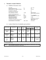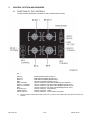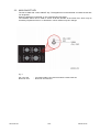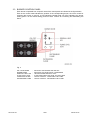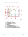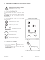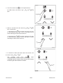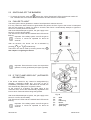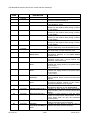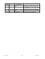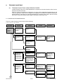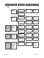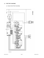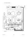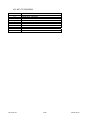
1
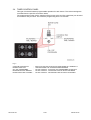
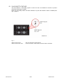
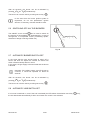
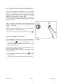
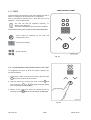
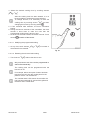
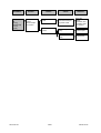
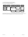
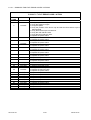
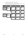
SERVICE MANUAL
COOKING
Built-in hobs
© ELECTROLUX ZANUSSI S.p.A.
Corso Lino Zanussi,30
I - 33080 PORCIA /PN (ITALY)
Tel +39 0434 394850
Fax +39 0434 394096
Publication
number
599 36 62-62
GAS HOBS WITH
ELECTRONIC IGNITION
EN/SERVICE/FV
SOI
Edition: 04.2005
SOI 04.05 FV
1/57
599 36 62-62
SOI 04.05 FV
2/57
599 36 62-62
TABLE OF CONTENTS
1.
INTRODUCTION ......................................................................................................................................... 6
PURPOSE OF THIS MANUAL ................................................................................................................ 6
ESD - Electrostatic Discharge and its effect on the components ............................................................ 6
GENERAL DESCRIPTION ...................................................................................................................... 6
2.
TECHNICAL CHARACTERISTICS ............................................................................................................. 7
2.1
GENERAL TECHNICAL DATA ................................................................................................................ 7
2.2
CHARACTERISTICS OF BURNERS AND NOZZLES ............................................................................ 7
3.
CONTROL SECTION AND BURNERS ....................................................................................................... 8
3.1
POSITIONS OF THE CONTROLS .......................................................................................................... 8
3.2
MAIN ON/OFF KEY ................................................................................................................................. 9
3.3
BURNER CONTROL PANEL................................................................................................................. 10
3.4
TIMER CONTROL PANEL..................................................................................................................... 11
3.5
CHILD SAFETY FEATURE.................................................................................................................... 12
4.
ELECTRONIC GAS CONTROL SYSTEM ................................................................................................ 13
4.1
OVERVIEW OF THE SYSTEM.............................................................................................................. 13
4.2
OPERATION OF THE SYSTEM ............................................................................................................ 14
4.3
BASIC CIRCUIT DIAGRAMS................................................................................................................. 15
BASIC CIRCUIT DIAGRAM: GAS SUPPLY AND CONTROL SYSTEMS.................................................... 15
IGNITION CIRCUIT - BASIC DIAGRAM ....................................................................................................... 16
4.4
SYSTEM COMPONENTS...................................................................................................................... 17
4.4.1 POWER BOARD .................................................................................................................................. 17
4.4.2 SENSOR CONTROL INTERFACE CIRCUIT BOARDS ...................................................................... 18
4.4.3 POWERED FLAME MODULATION VALVES...................................................................................... 20
Fig. 15............................................................................................................................................................ 21
4.4.4 MAIN SAFETY SOLENOID VALVE ..................................................................................................... 22
4.5
POSITIONS OF THE COMPONENTS INSIDE THE HOB .................................................................... 23
5.
OPERATING THE HOB (extract from Instruction Booklet) ....................................................................... 24
5.1
TOUCH CONTROL KEYS ..................................................................................................................... 24
5.2
LIGHTING THE BURNER...................................................................................................................... 24
5.3
SWITCHING OFF THE BURNERS........................................................................................................ 26
5.4
FAILURE TO LIGHT .............................................................................................................................. 26
5.5
IF THE FLAME GOES OUT (AUTOMATIC RE-IGNITION)................................................................... 26
5.6
SWITCHING OFF ALL THE BURNERS ................................................................................................ 27
5.7
AUTOMATIC BURNER SWITCH-OFF .................................................................................................. 27
5.8
AUTOMATIC HOB SWITCH-OFF.......................................................................................................... 27
5.9
PROTECTING AGAINST OVERHEATING ........................................................................................... 28
5.10
CHILD SAFETY FEATURE ................................................................................................................ 28
5.11
TIMER................................................................................................................................................. 29
5.10.1 PROGRAMMING THE BURNER SWITCH-OFF TIME...................................................................... 29
5.10.2 USING THE TIMER WITH THE BURNERS SWITCHED OFF/MINUTE-MINDER FUNCTION........ 31
6.
ADAPTING THE HOB TO DIFFERENT TYPES OF GAS......................................................................... 32
6.1
REPLACING THE NOZZLES................................................................................................................. 32
6.2
ADJUSTING THE HOB FOR THE TYPE OF GAS................................................................................ 32
6.3
ADJUSTING THE MINIMUM SETTING................................................................................................. 33
7.
ERROR CODES ........................................................................................................................................ 34
8.
TROUBLE-SHOOTING ............................................................................................................................. 37
8.1
TROUBLE-SHOOTING USING ERROR CODES ................................................................................. 37
8.1.1 ERRORS WITH BURNER BLOCK ...................................................................................................... 37
8.1.2 TROUBLE-SHOOTING WITHOUT ERROR CODES .......................................................................... 38
8.1.2 TROUBLE-SHOOTING WITHOUT ERROR CODES .......................................................................... 39
8.1.2 TROUBLE-SHOOTING WITHOUT ERROR CODES .......................................................................... 40
8.2
TROUBLESHOOTING WITHOUT ERROR CODE................................................................................ 42
9.
ACCESSIBILITY ........................................................................................................................................ 43
9.1
REMOVAL OF TOP FROM THE CABINET........................................................................................... 43
9.2
REMOVAL OF GAS SUPPLY CONNECTION ...................................................................................... 43
9.3
REMOVAL OF UPPER TOP.................................................................................................................. 44
9.4
ACCESS TO COMPONENT ZONE ....................................................................................................... 46
16 - MAIN SAFETY VALVE.................................................................................................................................. 46
9.4.1 DISMOUNTING THE BURNER CONTROL ELECTRICA VALVES .................................................... 47
9.4.2 DISMOUNTING THE MAIN SAFETY ELECTRIC VALVE................................................................... 48
9.4.3 REPLACEMENT OF INTERFACE BOARDS....................................................................................... 49
1.1
1.2
1.3
SOI 04.05 FV
3/57
599 36 62-62
9.4.4 REPLACEMENT OF POWER BOARD................................................................................................ 50
9.4.5 – REPLACEMENT OF BURNERS....................................................................................................... 51
9.4.6 REPLACEMENT OF THERMOCOUPLES .......................................................................................... 52
9.4.7 REPLACEMENT OF IGNITION SPARK PLUGS................................................................................. 54
10.
ELECTRIC DIAGRAMS............................................................................................................................. 55
10.1
BASIC ELECTRIC DIAGRAM ............................................................................................................ 55
10.2
WIRING DIAGRAM ............................................................................................................................ 56
10.3
KEY TO DIAGRAM............................................................................................................................. 57
SOI 04.05 FV
4/57
599 36 62-62
GENERAL PRECAUTIONS
-
These appliances are designed to operate using natural gas (methane) and LPG.
The appliances are factory-set for use with natural gas (methane). If a different type of gas is utilized (such
as LPG), the hob can be re-calibrated by replacing the gas nozzles.
-
It is essential to ensure that there is adequate air circulation around all gas appliances.
Inadequate ventilation, as well as causing the appliance to malfunction, may also result in a lack of
oxygen that might be hazardous for persons.
-
Installation and connection to the gas and electricity circuits must be carried out by qualified personnel in
compliance with all current safety legislation.
-
After being in use for a short time, and for some time after switching off, the cooking areas and the
surrounding surface will remain very hot.
A pilot lamp located on the hob remains lit until these cool down.
In order to avoid serious burns, it is important to ensure that no person touches the surface while
the pilot lamp is lit.
-
Do not switch on the burners without pans in the cooking areas, otherwise the hob may overheat and,
after a time, the burner will switch off.
SOI 04.05 FV
5/57
599 36 62-62
1.
INTRODUCTION
1.1 PURPOSE OF THIS MANUAL
The purpose of this Manual is to provide technical details regarding the new control system for
built-in gas hobs so that trouble-shooting and repairs cab be carried out correctly.
1.2 ESD - Electrostatic Discharge and its effect on the components
The interface for the control unit is not fitted with an internal device to protect against electrostatic
discharge (multiple connectors). When effecting repairs, therefore, the service engineer must
check for stabilization of the potential on the oven casing (i.e. discharge any static electricity by
touching the oven casing) in order to prevent the possibility of overload, which might damage the
control unit.
The same care is necessary when handling control units supplied as spare parts (i.e. not yet fitted
to the oven), which must be removed from the protective bag in ESD only after stabilizing the
potential (i.e. discharging any static electricity) and only then installed in the appliance.
Important: The theory behind the process of electrostatic charge and discharge is not discussed in
this Manual, since the tangible effects are considered to be more important. However, the effects
are felt frequently when touching a metal handle and feeling the electrostatic discharge in the form
of a minor shock.
But what happens when stabilization of the potential takes place with semi-conductor components
(i.e. components on a circuit board, such as integrated circuits, microprocessors etc.)?
Stabilization of the potential takes place across the internal structure of the component. This does
not necessarily lead to the immediate destruction of the component; subsequent malfunctions
across damaged internal connections may be more harmful, and these occur only as a result of
overheating or current overloads.
It is true that almost all sensitive semi-conductor components (such as MOS circuits) have been
improved by the addition of protective measures, but the internal structures of these components
are today smaller than, for example, ten years ago, which tends to increase their sensitivity to the
previous levels.
Important!
Which components are susceptible to damage by static electricity during repairs?
All circuit boards featuring control and command accesses (door switches, food probes etc.), bare
tracks and microprocessors, as well as any other circuits with free access.
Examples:
-
Programmers with access to the food probe and the door switch.
Programmers whose control processors are accessible (due to their high costs, the protective
systems are only partial).
W.O.E.C. control units.
S.O.E.C. control units.
C.H.E.C. control units.
KRONOS control units.
Interface board of the Electronic gas hob.
1.3 GENERAL DESCRIPTION
In these hobs, the burners are controlled entirely by a special electronic system that actions special
solenoid valves which regulate the quantity of gas delivered to the burners.
With the introduction of this electronic control system, it is now possible to fit Touch Control keys,
as well as to provide greater safety, such as automatic re-lighting of the burners, and several
control functions, including indication of residual heat, child safety feature, interruption of all
operations using a single switch, safety cut-off in case of power failure or failure to light, automatic
timer-controlled switching off and programmed operation of the burners. These functions are
described in this manual.
SOI 04.05 FV
6/57
599 36 62-62
2.
TECHNICAL CHARACTERISTICS
2.1 GENERAL TECHNICAL DATA
VOLTAGE
POWER ABSORPTION
DIMENSIONS OF CABINET (HxWxD)
V
W
cm
220 - 230
20
3x71x47
AUTOMATIC IGNITION:
AUTOMATIC RE-IGNITION
GAS CONTROL SYSTEM
TYPE
SAFETY SOLENOID VALVE
MODULATION SOLENOID VALVE
RAPID BURNERS:
SEMI-RAPID BURNERS:
AUXILIARY BURNERS:
TEMPERATURE LIMITS
N°
N°
N°/kW
N°/kW
N°/kW
°C
AUTOMATIC BURNER SWITCH-OFF
PROGRAMMING OF BURNERS
MAX. TIME.
SI
SI
ELECTRONIC
WITH TOUCH CONTROL
1
4 (1 x BURNER)
1 / 2,9 (G20) – 2,7 (G30)
2 / 1,9
1 / 1,0
95°C Burner at minimum
105°C Hob is cut off
After 4 hours
40 minutes
2.2 CHARACTERISTICS OF BURNERS AND NOZZLES
Type of GAS
Type of burner
(R - L)
Nozzle
marking
(mm/100)
Nominal
thermal
delivery
kW
Nominal delivery in
m3/h
g/h
Nominal
pressure
(mbar)
Natural gas
(methane)
(G20)
Rapid :
Semi-rapid :
Auxiliary :
119
96
70
2,6
1,6
1,6
0,286
0,181
0,095
-
20
Natural gas
(methane)
(G25)
Rapid :
Semi-rapid :
Auxiliary :
124
100
71
2,6
1,6
1,6
0,286
0,181
0,095
-
25
LPG/Propane
or
(G30)
(G31)
Rapid :
Semi-rapid :
Auxiliary :
86
71
50
2,5
1,6
1,6
-
195
137
72
28-30 (G30)
37 (G31)
(*) Certain models only
NOTE : The consumption and delivery figures are approximate; the exact values are shown
in the instruction booklets for each model.
SOI 04.05 FV
7/57
599 36 62-62
3.
CONTROL SECTION AND BURNERS
3.1 POSITIONS OF THE CONTROLS
The figure below illustrates the positions of the controls and the burners.
Fig. 1
BR-R (*)
BR-S/R 1
BR-S/R 2
BR-A
BR-R CONTROL
BR-S/R 1 CONTROL
BR-S/R 2 CONTROL
BR-A
MAIN ON /OFF
TIMER BOARD
SAFETY BLOCK
(*)
SOI 04.05 FV
-
RAPID BURNER (FRONT-RIGHT)
SEMI-RAPID BURNER (REAR-LEFT)
SEMI-RAPID BURNER (REAR-RIGHT)
AUXILIARY BURNER (FRONT-LEFT)
TOUCH CONTROL FOR RAPID BURNER (FRONT-RIGHT)
TOUCH CONTROL FOR SEMI-RAPID BURNER (REAR-LEFT)
TOUCH CONTROL FOR SEMI-RAPID BURNER (REAR-RIGHT)
TOUCH CONTROL FOR AUXILIARY BURNER (FRONT-LEFT)
TOUCH CONTROL - MAIN ON/OFF
TOUCH CONTROL - TIMER
TOUCH CONTROL - CHILD SAFETY FEATURE
Certain models are fitted with a triple-crown burner in place of the rapid burner (see table of burners and
nozzles)
8/57
599 36 62-62
3.2 MAIN ON/OFF KEY
The hob is fitted with a main ON/OFF key. The appliance must be switched on before the burners
can be ignited.
When the appliance is switched on, the corresponding LED lights.
The ON/OFF switch can be used to switch off all the burners at the same time, which may be
necessary if liquids boil over or in situations in which children may be in danger.
Fig. 2
ON / OFF LED
MAIN ON / OFF
SOI 04.05 FV
-
LED INDICATING THAT THE APPLIANCE IS SWITCHED ON
MAIN ON / OFF SWITCH
9/57
599 36 62-62
3.3 BURNER CONTROL PANEL
Each burner is operated from a specific area of the control panel as indicated in the figure below.
Each of the control areas indicates the position of the corresponding burner, the touch control for
switching the burner on and off, a LED indicating residual heat, six LEDs indicating the burner
setting (level 0 is the lowest setting) and two touch controls for increasing and decreasing the
flame.
Fig. 3
ON / OFF BURNER
BURNER ZONE
RESIDUAL HEAT LED
FLAME LEVEL LEDS
INCREASING FLAME
DECREASING FLAME
SOI 04.05 FV
-
SWITCHES THE BURNER ON AND OFF
INDICATES THE POSITION OF THE BURNER
LED INDICATING RESIDUAL HEAT
6 LEDs INDICATING THE LEVEL OF THE FLAME
TOUCH CONTROL - INCREASES THE FLAME
TOUCH CONTROL - DECREASES THE FLAME
10/57
599 36 62-62
3.4 TIMER CONTROL PANEL
This type of hob also features programmable operation for each burner. The various settings are
controlled from the specific zone shown below.
The programming function (which switches off the burner at the end of a preset time) can be used
for one burner only at a time. The maximum programming time is 40 minutes.
Fig. 4
COOKING TIME DISPLAY
BURNER ZONE LED
ON / OFF PROGRAMME
INCREASING TIME / BURNER
DECREASING TIME / BURNER
SOI 04.05 FV
-
DISPLAYS THE TIME FOR WHICH THE BURNER WILL REMAIN LIT
LED INDICATING THE CORRESPONDING BURNER
TOUCH CONTROL - SWITCHES THE PROGRAMME ON AND OFF
TOUCH CONTROL - INCREASES TIME OR SELECTS BURNER
TOUCH CONTROL - DECREASES TIME OR SELECTS BURNER
11/57
599 36 62-62
3.5 CHILD SAFETY FEATURE
The hob features a child safety system in which the user can disable the controls to prevent
inadvertent actioning by children.
When the child safety feature has been selected, only the main ON/OFF switch is enabled (see
Fig. 2, page 9).
Fig. 5
SAFETY BLOCK LED
SAFETY BLOCK ON / OFF
SOI 04.05 FV
-
LED: CHILD SAFETY FEATURE ON
TOUCH CONTROL: SWITCHES ON CHILD SAFETY FEATURE
12/57
599 36 62-62
4.
ELECTRONIC GAS CONTROL SYSTEM
4.1 OVERVIEW OF THE SYSTEM
This electronic system is designed to be fitted to Electrolux "Gas on Glass" built-in hobs
(70x60 cm) with uncovered burners.
Its main characteristics are as follows:
SOI 04.05 FV
-
Control of four current-production Electrolux burners (uncovered): one rapid, two semi-rapid,
one auxiliary.
-
Hob in special high-strength safety glass (thickness up to 8 mm).
-
Ignition system with 230V spark generator and spark plug.
-
Flame detection with thermocouple.
-
Wiring circuit comprising the following:
- Connection between circuit board and valves.
- Connection between circuit board and spark generator.
- Connection between circuit board and power circuit.
- Connection between circuit board and thermocouples.
- Connection between interface circuit boards and power board.
-
Electronic control system comprising:
- Power board.
- Interface board (left)
- Interface board (right)
- General interface board with: ON/OFF, child safety feature, timer module, display.
-
The following gas valves are featured:
- A main safety valve (automatic)
- A modulation valve for each burner (four in total)
-
User interface system with touch control: each interface controls two burners.
Each interface board has the following characteristics:
- "+" and "–" touch controls for adjustment of the flame.
- Flame level indicator: 6 levels with LED indication (Levels 1 - 5: modulation; level 6: valve
completely open).
- LED indicators: one LED lights to indicate that the burner is in operation; a second LED
warns the user about residual heat around each burner.
The general interface has the following characteristics:
- "ON" AND "OFF" controls.
- Timer function with display module
- Child safety function.
-
A single version of the power board which can be customized via software.
-
Easily-customized user interface software.
13/57
599 36 62-62
4.2 OPERATION OF THE SYSTEM
When the user wishes to light one of the burners using the touch control on the burner control
panel, the main safety valve VS (Fig. 6) opens (unless the valve is already open and feeding a
different burner). The corresponding modulation valve VM opens and the spark generator actions
the spark plug which ignites the burner.
The burner is always ignited at maximum setting. At this point, the flame detection procedure takes
place. If the burner has failed to ignite, the ignition system makes two more attempts.
On each burner, the level of the flame can be adjusted using keys
setting is displayed by the flame level LEDs.
or
while the flame
In the event of problems with a burner (e.g. if the burner is wet etc.) and the main switch is set to
ON, it is possible to disable only the valve (VM) relative to that burner, using the touch control
.
This interrupts the supply of gas only to the single burner, while the remaining burners continue to
operate normally.
If the power supply is switched off or if the electronic control system detects a malfunction (e.g. a
problem with the electrical connections), the main valve VS and the corresponding modulation
valve VM intervene to cut off the gas supply to the burners.
In all cases, therefore, the gas supply to the burners is controlled by at last two safety valves. After
a power failure, the system remains disabled, which is indicated by the flashing of all the LEDs in
the hob control zone. To restore the burners to normal operation after a power failure (LEDs
flashing), it is necessary to wait at least 60 seconds and then press buttons
simultaneously and then button
and
,
, after which the burner can be used normally.
The presence of residual heat on and around the burners is indicated by the corresponding LEDs
positioned on the hob control panels.
If the temperature in the electronic section should exceed about 95°C, in order to prevent possible
damage, the system reduces all the burners to the lowest setting; if the temperature should exceed
105°C, then all the safety valves that control the supply to the burners are closed and an error
code is displayed.
SOI 04.05 FV
14/57
599 36 62-62
4.3 BASIC CIRCUIT DIAGRAMS
BASIC CIRCUIT DIAGRAM: GAS SUPPLY AND CONTROL SYSTEMS
Fig. 6
IN GAS
VS
VM
SP
TC
BR-R
BR-S/R
BR-A
TIMER BOARD
TOUCH DX BOARD
TOUCH SX BOARD
SOI 04.05 FV
-
GAS INLET
MAIN SAFETY VALVE
POWERED MODULATION VALVE
SPARK PLUG
THERMOCOUPLE
RAPID BURNER
SEMI-RAPID BURNER
AUXILIARY BURNER
MAIN TOUCH-CONTROL INTERFACE BOARD
RH TOUCH-CONTROL INTERFACE BOARD
LH TOUCH-CONTROL INTERFACE BOARD
15/57
599 36 62-62
IGNITION CIRCUIT - BASIC DIAGRAM
Lighting of the burners is performed by the spark plugs, which are powered by a single spark
generator actioned by the power board.
Fig. 7
SP
TC
BR-R
BR-S/R
BR-A
POWER BOARD
TIMER BOARD
TOUCH DX BOARD
TOUCH SX BOARD
SOI 04.05 FV
-
SPARK PLUG
THERMOCOUPLE
RAPID BURNER
SEMI-RAPID BURNER
AUXILIARY BURNER
POWER BOARD
MAIN TOUCH-CONTROL INTERFACE BOARD
RH TOUCH-CONTROL INTERFACE BOARD
LH TOUCH-CONTROL INTERFACE BOARD
16/57
599 36 62-62
4.4 SYSTEM COMPONENTS
The system comprises four circuit boards: one power board and three interface boards. The hob
controls are divided among the three general interface boards:
- General interface and timer board.
- RH interface board, connected directly to the general interface board.
- LH interface board, identical to the RH board but connected directly to the power board.
The gas is controlled by a main safety solenoid valve and by four powered modulation valves (one
for each burner).
The presence of a flame is detected by four thermocouples (one for each burner).
4.4.1 POWER BOARD
The power board is customized by a software that defines all the system's control and safety
parameters. This software is entered on completion of the production of the hob.
The main functions of the power board are as follows:
-
Control for spark generator for
lighting the burners.
Flame presence detection by
thermocouples
Control of the main safety valve.
Control of the modulation valve for
each burner.
Regulation, control and diagnostics
for each burner.
Fig. 8
Fig. 8
AUX1
TC1
TC2
TC3
TC4
BC1
BC2
BC3
BC4
BCX
N
PE
LO
L
SOI 04.05 FV
-
SERIAL LINE
CONNECTION TO INTERFACE BOARD
CONNECTION TO INTERFACE BOARD
CONNECTION TO INTERFACE BOARD
CONNECTION TO INTERFACE BOARD
POWER TO SOLENOID VALVE - BURNER BR-A
POWER TO SOLENOID VALVE - BURNER BR-R
POWER TO SOLENOID VALVE - BURNER BR-S/R 2
POWER TO SOLENOID VALVE - BURNER BR-S/R 1
POWER TO MAIN SAFETY SOLENOID VALVE
POWER SUPPLY (NEUTRAL)
EARTH
POWER TO SPARK GENERATOR
POWER SUPPLY (LIVE)
17/57
599 36 62-62
4.4.2 SENSOR CONTROL INTERFACE CIRCUIT BOARDS
This hob is provided with a touch sensor control
device.
To insert the controls in the hob, some sensors
interface electronic PCBs are used in place of the
normal buttons which control the switches placed in
the control unit.
The system consists of sensor PCBs placed under
the glass which recognise the presence of a finger
at a distance of about 4 mm from the sensors (glass
thickness).
The sensor PCBs include different control units with
touch sensors used on the basis of the control
software (see Fig. 9, 10 and 11).
Fig. 9
The functions of the various controls and of the LEDs and displays are listed below.
BOARD FOR LEFT FRONT AND
LEFT REAR SECTIONS
Fig. 10
ON / OFF
BR-S/R 1 BURNER
ON/OFF - REAR LEFT BURNER
BR-S/R 1 RESIDUAL
HEAT LED
RESIDUAL HEAT - REAR LEFT
BURNER
BR-S/R 1 FLAME
LEVEL LEDS
FLAME LEVEL LEDs - REAR
LEFT BURNER
BR-S/R 1
DECREASING
FLAME
DECREASE FLAME - REAR
LEFT BURNER
BR-S/R 1
INCREASING
FLAME
INCREASE FLAME - REAR LEFT
BURNER
ON / OFF
BR-R BURNER
ON/OFF - FRONT LEFT
BURNER
BR-R RESIDUAL
HEAT LED
RESIDUAL HEAT - FRONT
LEFT BURNER
BR-R FLAME
LEVEL LEDS
FLAME LEVEL LEDs - FRONT
LEFT BURNER
BR-R
DECREASING
FLAME
DECREASE FLAME - FRONT
LEFT BURNER
BR-R
INCREASING
FLAME
INCREASE FLAME - FRONT
LEFT BURNER
SOI 04.05 FV
18/57
599 36 62-62
MAIN BOARD / TIMER
Fig. 11
BR-S/R 1 LED
LED FOR REAR LEFT BURNER
BR-S/R 2 LED
LED FOR REAR RIGHT
BURNER
BR-A LED
LED FOR FRONT LEFT
BURNER
BR-R LED
LED FOR FRONT RIGHT
BURNER
ON / OFF
BR-S/R 2 BURNER
ON/OFF - REAR RIGHT
BURNER
BR-S/R 2 RESIDUAL
HEAT LED
RESIDUAL HEAT - REAR
RIGHT BURNER
BR-S/R 2 FLAME
LEVEL LEDS
FLAME LEVEL LEDs - REAR
RIGHT BURNER
BR-S/R 2
DECREASING
FLAME
DECREASE FLAME - REAR
RIGHT BURNER
BR-S/R 2
INCREASING
FLAME
INCREASE FLAME - REAR
RIGHT BURNER
ON / OFF
BR-R BURNER
ON/OFF - FRONT RIGHT
BURNER
BR-R RESIDUAL
HEAT LED
RESIDUAL HEAT - FRONT
RIGHT BURNER
BR-R FLAME
LEVEL LEDS
FLAME LEVEL LEDs - FRONT
RIGHT BURNER
BR-R
DECREASING
FLAME
DECREASE FLAME - FRONT
RIGHT BURNER
BR-R
INCREASING
FLAME
INCREASE FLAME - FRONT
RIGHT BURNER
BOARD FOR RIGHT FRONT
AND RIGHT REAR SECTIONS
SOI 04.05 FV
19/57
599 36 62-62
4.4.3 POWERED FLAME MODULATION VALVES
The flame control valves comprise two sections: the modulation section and the safety valve section.
Fig. 11
1
2
3
4
-
5
6
-
ELECTRICAL CONNECTORS (FASTONS)
CONNECTOR FOR MODULATION MOTOR
VALVE SOLENOID
MODULATION MOTOR (STEPPING LINEAR
ACTUATOR)
GAS INLET COUPLING
GAS DELIVERY COUPLING
The modulation section SM comprises a pressure regulator which, by means of a stepping linear actuator
APP, compresses the regulation spring M1 , thus obtaining one of the six levels of closure of element O1.
The output pressure varies according to the compression of the spring M1 and therefore according to the
electronic control system.
When actuator APP is in the minimum compression position of spring M1, the closing element O1 is
forced into the closed position by spring M2. On the contrary, when the actuator is at maximum position
(i.e. when the flame is at maximum setting), the closing element O1 is forced into the completely-open
position.
In this way the SM assembly acts as a modulator for the delivery pressure and therefore for the power of
the burner (flame setting). The SM assembly also serves to cut off the gas.
The safety solenoid section EV consists of a control coil EM and a closure element O2, and acts as a
safety valve.
Fig. 12
APP
EM
EV
M1
M2
O1
O2
SM
-
LINEAR STEPPING ACTUATOR (MOTOR)
CONTROL COIL
SAFETY VALVE
REGULATION SPRING
CLOSURE SPRING
MODULATOR CLOSING ELEMENT
CLOSING ELEMENT FOR SAFETY VALVE
MODULATOR
SOI 04.05 FV
20/57
599 36 62-62
OUTPUT PRESSURE (mbar)
PRESSURE DIAGRAM WITH 20mbar NATURAL GAS
NO. OF STEPS
Fig. 14
OUTPUT PRESSURE (mbar)
PRESSURE DIAGRAM WITH 37mbar LIQUID GAS
NO. OF STEPS
Fig. 15
SOI 04.05 FV
21/57
599 36 62-62
MODULATION CONTROL MOTOR (STEP-BY-STEP)
The modulation control motor of the solenoid valves is a unipolar step-by-step type.
Please find below the connection diagram of the motor and the rotation diagram.
MOTOR CONNECTION DIAGRAM
MOTOR CONNECTOR
BLK Black
RED Red
BRW Brown
ORG Orange
YEL Yellow
BLK RED BRW
ORG RED YEL
ANTI-CLOCKWISE ROTATION
CLOCKWISE
ROTATION
ROTATION DIAGRAM
BLK
BRW
ORG
YEL
RED/
RED
A
BLK
A COM
RED
_
A
BRW
UNIPOLAR
MOTOR
B
ORG
_
B
YEL
ROTATION DIAGRAM STARTING FROM THE PAUSE POSITION
Fig. 17
4.4.4 MAIN SAFETY SOLENOID VALVE
The function of the main safety valve is to provide an extra safety feature in controlling the
delivery of gas.
The internal structure and the operation of the valve are identical to the EM section of the
burner control valves described in the corresponding section.
Fig. 17
1
2
3
4
SOI 04.05 FV
-
ELECTRICAL CONNECTOR (FASTON)
SOLENOID
GAS DELIVERY COUPLING
GAS INLET COUPLING
22/57
599 36 62-62
4.5 POSITIONS OF THE COMPONENTS INSIDE THE HOB
The figure below shows the positions of the various components inside the hob.
Fig. 18
1
2
3
4
5
6
7
8
9
10
11
12
13
14
15
SOI 04.05 FV
-
MAIN SAFETY SOLENOID VALVE
LEFT REAR BURNER BR-S/R 1 (SEMI-RAPID)
TERMINAL BLOCK FOR POWER SUPPLY
SPARK GENERATOR
RIGHT REAR BURNER BR-S/R 2 (SEMI-RAPID)
GENERAL INTERFACE BOARD (TOUCH CONTROL)
POWER BOARD
RIGHT FRONT BURNER BR-R (RAPID)
LEFT FRONT BURNER BR-A (AUXILIARY)
CONTROL VALVE FOR LEFT FRONT BURNER BR-A (AUXILIARY)
LEFT INTERFACE BOARD (TOUCH CONTROL)
CONTROL VALVE FOR RIGHT FRONT BURNER BR-R (RAPID)
CONTROL VALVE FOR RIGHT REAR BURNER BR-S/R 2 (SEMI-RAPID)
CONTROL VALVE FOR LEFT REAR BURNER BR-S/R 1 (SEMI-RAPID)
POWER BOARD
23/57
599 36 62-62
5.
OPERATING THE HOB (extract from Instruction Booklet)
Before using the appliance, remove all
packaging material, including advertising
labels and protective film, if any.
5.1 TOUCH CONTROL KEYS
The hob is operated using special "touch control" sensor
keys.
To operate the hob, simply touch the appropriate sensor
with a fingertip.
Do not touch more than one sensor at a time when
operating the hob.
The symbols listed below indicate the functions of the
various touch keys.
BURNER CONTROL AREA
Main ON/OFF (touch control)
Light burner (touch control)
Flame level indicator LEDs
Increase flame setting
Reduce flame setting
Residual heat warning LED
Fig. 19
5.2 LIGHTING THE BURNER
1. Touch the main ON/OFF key
for three seconds to
switch the hob on.
The red LED above the touch control will light, and the
buzzer will sound.
The hob is now ready for use.
Fig. 20
SOI 04.05 FV
24/57
599 36 62-62
2. Touch the sensor key
for the required burner.
All LEDs above the sensor keys
light.
and
will
Fig. 21
3. Within 3 seconds touch the sensor key
turn on the burner.
or
.to
is touched the burner will turn
- If the sensor key
on automatically at the max. level of the flame (all the
LEDs indicating the flame level remain lit.
is touched, the burner will turn
- If the sensor key
on automatically at medium level of the flame (3 LEDs
indicating the flame level remain lit).
Fig. 22
4. To increase or reduce the flame level of the burner, use
the sensor keys
or
.
lights
The
residual
heat
pilot
lamp
immediately after the switching on of the burner.
It indicates that the cooking zone heats up and remains
lit until the grill and the burner cool down.
Fig. 23
SOI 04.05 FV
25/57
599 36 62-62
5.3 SWITCHING OFF THE BURNERS
1. To switch off a burner, touch the
sensor key. All the "flame level" LEDs for the burner switch off.
The "residual heat" LED remains lit until the burner and the hob have cooled down.
5.4 FAILURE TO LIGHT
The hob's ignition device generates a series of small sparks for about 6 seconds.
If for any reason the flame should not ignite within this period, the flow of gas to the burner is interrupted
and the hob remains in "pause" for about 3 seconds, after which it automatically attempts to ignite the
burner for a further period of 6 seconds.
After three failed attempts at ignition, the gas supply to the
burner is cut off to ensure safety.
The "flame level" LEDs and the "residual heat" LED remain
flashing.
Important: If the safety system cuts off the gas to
a burner, it cannot be operated for about 60
seconds.
After 60 seconds, the burner can be re-activated by
and
pressing
simultaneously.
The burner can now be used by touching sensor key
See chapter 5.2 Lighting the burner.
.
Fig. 24
Important: Ensure that the crown, the cap and the
grille are correctly positioned (see figure opposite)
5.5 IF THE FLAME GOES OUT (AUTOMATIC
RE-IGNITION)
If the burner should for any reason be extinguished (by
draughts, overflowing liquids etc.), the flow of gas is
immediately interrupted. Then, after about 20 seconds, the
hob automatically attempts to re-ignite the flame.
At the moment of re-ignition, the flame lights at the
maximum level, and is then automatically regulated to the
level to which it was set before being extinguished.
Fig. 25
After three failed attempts at ignition, the gas supply to the
burner is cut off to ensure safety.
The "flame level" LEDs and the "residual heat" LED remain
flashing.
Important: If the safety system cuts off the gas to
a burner, it cannot be operated for about 60
seconds.
SOI 04.05 FV
26/57
A
B
C
D
E
F
-
Grille
Cap
Flame ring
Burner
Thermocouple
Spark plug
599 36 62-62
After 60 seconds, the burner can be re-activated by
and
pressing
simultaneously.
The burner can now be used by touching sensor key
In the event that the burner ignition system is
inoperative, do not use piezoelectric ignition
devices. If necessary, matches should be used.
5.6 SWITCHING OFF ALL THE BURNERS
The ON/OFF touch control
can be used to switch all
the burners off immediately and simultaneously, in case of
emergencies or unexpected events (overflowing liquids,
situations of danger involving children etc.)
Fig. 26
5.7 AUTOMATIC BURNER SWITCH-OFF
In the event that the user should forget to switch off a
burner and does not adjust the controls, the burner will
switch off automatically after four hours.
In this event, the gas supply is disconnected and the burner
is blocked.
Important: If the safety system cuts off the gas to
a burner, it cannot be operated for about 60
seconds.
After 60 seconds, the burner can be re-activated by
pressing
and
simultaneously.
The burner can now be used by touching sensor key
5.8 AUTOMATIC HOB SWITCH-OFF
If no burner is switched on, even if the hob is activated (the LED above the activation touch key
the hob deactivates automatically if within 30 minutes one control is not activated.
SOI 04.05 FV
27/57
is on),
599 36 62-62
5.9 PROTECTING AGAINST OVERHEATING
If the hob is subjected to intensive use, e.g. if several
burners are operated for long periods at maximum flame
setting, a temperature sensor checks for possible
overheating and, if necessary, automatically reduces the
settings of all the burners to minimum level.
If, in spite of this reduction, the temperature continues to
rise, the burners are all switched off and the hob enters
safety block mode.
Important: If the safety system cuts off the gas to
all the burners, they cannot be operated for about
60 seconds.
After 60 seconds, the burner can be re-activated by
pressing
and
simultaneously.
The burner can now be used by touching sensor key
5.10 CHILD SAFETY FEATURE
The "Child safety" feature allows the user to disable all the
hob controls to prevent them from being inadvertently used.
Fig. 22
1. Press touch key
for about three seconds
The red pilot lamp positioned above the touch key lights
and the buzzer sounds.
Now, all the controls on the hob are disabled, with the
exception of the ON/OFF sensor key.
Any burners that are lit will remain lit, but the flame setting
cannot be altered.
2. To re-enable the controls, press touch key
for about
three seconds.
The red pilot lamp switches off and the buzzer sounds.
SOI 04.05 FV
28/57
599 36 62-62
TIMER CONTROL PANEL
5.11 TIMER
The hob features an electronic timer that enables the user to
select a cooking time when the burner is in operation.
Also, it is possible to use the timer – when the hob is not in
operation – as a minute-minder.
The hob can also be operated manually, i.e.
without using the timer.
The timer is inoperative when the hob is disabled.
The symbols on the timer control zone are described below.
Touch control for switching on the timer and
selecting the burner.
Cooking time display
Burner selected
Fig. 23
5.10.1 PROGRAMMING THE BURNER SWITCH-OFF TIME
To programme the time at which the burner switches off,
proceed as follows:
1. If necessary, switch on the hob by touching the ON / OFF
touch key for about three seconds.
2. Light the burner by touching the touch control
and
or
to adjust the flame setting
use touch keys
(see "LIGHTING THE BURNER")
3. Switch on the timer and select the desired burner by
touching sensor
until the correct burner is displayed.
Fig. 24
SOI 04.05 FV
29/57
599 36 62-62
4. Select the desired cooking time by touching sensors
or
.
After the cooking time has been entered, it is no
longer possible to change the burner selected.
To change burners, it is necessary to reset the
cooking time by touching sensor
, and then
.
changing the burner by touching sensor
5. A few moments after selection, the timer countdown
begins.
6. During the last ten seconds of the countdown, the timer
sounds a short buzz to warn the user that the
programmed cooking time is about to end.
7. At the end of the time entered, the buzzer sounds. Touch
sensor
to switch off the buzzer.
5.10.1.1 Modifying the programmed setting
1. At any time, touch sensors
decrease the time entered.
or
to increase or
Fig. 25
5.10.1.2 Resetting the minute-minder setting
1. Touch sensor
to reduce the time to zero.
Only one burner at a time can be programmed to
switch off automatically.
The cooking time can be programmed with the
burner lit or off.
For example, after a saucepan of water has been
brought to the boil, then the cooking time for the
pasta or rice etc. can be entered.
The "residual heat" LEDs remain lit even after the
hob has been switched off, and until the grille and
the burner have cooled down.
SOI 04.05 FV
30/57
599 36 62-62
5.10.2 USING THE TIMER WITH THE BURNERS
SWITCHED OFF/MINUTE-MINDER FUNCTION
To use the timer as a minute-minder, the hob must be
switched on.
To use this function, proceed as follows:
1. If necessary, switch on the hob by touching the ON / OFF
touch key for about three seconds. .
2. Touch sensor key
to switch on the timer.
or
to select the desired
3. Touch sensor keys
time (maximum setting: 99 minutes).
4. A few instants after entering the selected time, the timer
countdown will begin.
5. The display shows the last minute of the countdown
second by second.
When the programmed time has elapsed, the buzzer
sounds.
6. To switch off the buzzer, touch sensor key
.
Fig. 26
5.10.2.1 Modifying the minute-minder setting
1. At any time, touch sensors
decrease the time entered.
or
to increase or
5.10.2.2 Resetting the minute-minder setting
1. Touch sensor
to reduce the time to zero.
Fig. 27
SOI 04.05 FV
31/57
599 36 62-62
6.
ADAPTING THE HOB TO DIFFERENT TYPES OF GAS
6.1 REPLACING THE NOZZLES
IMPORTANT: Category "II2H3+" hobs (see
"Technical Characteristics") are not designed
for conversion to operation with town gas.
1. Remove the grilles.
2. Remove the caps and the flame rings from the burners.
3. Use a 7mm hex wrench to unscrew and remove the
nozzles.
Replace the nozzles with those corresponding to the type
of gas to be used (see "Technical Characteristics").
4. Re-assemble the burner, performing the same procedure
in reverse sequence.
5. Replace the gas calibration label (positioned near the
gas inlet coupling) with the label showing the new type of
gas. The new label is included in the plastic bag
containing the injectors.
If the gas pressure is not as specified for the appliance (or if
the pressure is variable), it is necessary to install a pressure
regulator suitable for ducted gas (NOT LPG), and compliant
with UNI-CIG standard 7430, on the inlet hose.
The use of pressure regulators designed for liquid gas (LPG)
is permitted, on condition that these are compliant with UNICIG standard 7432.
Fig. 28
6.2 ADJUSTING THE HOB FOR THE TYPE OF
GAS
1. If necessary, switch on the hob by touching the ON / OFF
touch key for about three seconds.
to select the auxiliary burner on
2. Touch sensor key
the burner display window.
3. Touch sensor key
Fig. 29
until the display shows "99".
until the display shows "80".
Then touch sensor key
Then touch the sensor key again until the display shows
"83".
This procedure places the hob in "change gas" mode; the
display will show the type of gas currently selected.
to select the type of gas.
4. Touch sensor key
The display shows some codes (from "n0" to "n2") which
indicate the type of gas relative to the appliance. (See
User manual).
5. After selecting the type of gas, switch off the hob by
touching the ON/OFF sensor
.
6. Switch the appliance on again. The hob will automatically
switch on in "user mode".
Fig. 30
SOI 04.05 FV
32/57
599 36 62-62
7. Light all the burners and adjust the flame setting to
minimum to check the stability of the flame (rapid
changing from a min to a max. and vice versa without
switching off the burner).
8. At the same time, check the appearance of the flame (no
smoke, yellow bits, no flame detachments).
If the flame is normal and stable, the "gas change"
procedure is complete.
However, if the flame is not stable when at minimum setting,
it is necessary to make the adjustments described below.
6.3 ADJUSTING THE MINIMUM SETTING
Fig. 31
Proceed as follows to adjust the minimum setting correctly:
1. Carry out the operations described in "Adjusting the hob
for the type of gas", steps 1, 2, 3 and 4.
to ignite the burner to be
2. Touch the sensor key
adjusted.
The burner will automatically be set to the minimum
flame setting.
3. If the minimum flame is in fact too small, the burner will
go out. The hob automatically adjusts the minimum flame
setting and re-lights the burner.
4. With the burner lit, touch sensor keys
or
make
fine adjustments until the flame is small and even around
the entire perimeter of the crown.
5. Touch the ON/OFF sensor
to switch off the hob.
Fig. 32
NOTE :
If after adjusting the minimum setting, the flame is still
producing smoke, with yellow bits or possible flame
detachments, it is necessary to check the pressure and
eventually type and composition of the gas.
Fig. 33
SOI 04.05 FV
33/57
599 36 62-62
7.
ERROR CODES
The electronic control system performs an internal autodiagnostics routine. If an operating malfunction is
detected, the corresponding error code is displayed.
To display the error codes, it is sufficient to touch the "clock" sensor and then select the inoperative burner. The
error code will be displayed automatically (see Fig. 39 and 40).
If the malfunction affects not one single burner but the entire hob, the same code will be displayed for each
burner.
Fig. 39
SOI 04.05 FV
Fig. 40
34/57
599 36 62-62
The table below lists the various error codes with their meanings.
ERROR
COSE
0
1
BURNER
ERROR CODE
DESCRIPTION
NO ERROR
NO FLAME AFTER RETRY
2
BURNER
EV FEEDBACK FAULT
3
BURNER
SM PHASE 1 FAULT
4
BURNER
SM PHASE 2 FAULT
5
BURNER
SM PHASE 3 FAULT
6
BURNER
SM PHASE 4 FAULT
7
BURNER
SM ENABLE FAULT
8
BURNER
GENERIC FAULT
9
SYSTEM
TEMPERATURE OUT OF
RANGE FAULT
10
BURNER
CONTINUOUS RUN
11
SYSTEM
POWER
FAULT
SUPPLY
VPP
12
SYSTEM
POWER
FAULT
SUPPLY
VDD
14
BURNER
ABNORMAL
CONDITION
15
SYSTEM
SYSTEM LOCKEED FATAL
FAULT
16
SYSTEM
NTC SENSOR FAULT
17
SYSTEM
TIME BASE RATIO FAULT
18
SYSTEM
AD CONVERTER FAULT
19
SYSTEM
DATA MEMORY FAULT
20
SYSTEM
PROGRAM
CONFIGURATION MEMORY
FAULT
SOI 04.05 FV
BLOCK
--
TC
35/57
CAUSE
Normal condition for an operating burner.
Condition of the burner after 3 consecutive
attempts of failed switching on.
Condition of the burner in case of “solenoid
valve feedback” wrong.
Condition of the burner in case of error signal
referring to the relative valve (wrong contacts
on the cables).
Condition of the burner in case of error signal
referring to the relative valve (wrong contacts
on the cables).
Condition of the burner in case of error signal
referring to the relative valve (wrong contacts
on the cables).
Condition of the burner in case of error signal
referring to the relative valve (wrong contacts
on the cables).
Condition of the burner in case of global error
signal or referred to more simultaneous errors.
Generic error condition of the burner in case
the cause does not have a specific code.
Condition of the burner in case the
temperature detected on the power board
exceeds 105°C.
Condition of the burner in case of continuous
operation longer than 4 hours without any
alteration of the flame level.
Condition of the burner in case the ratio
between the supply values on the power board
is not correct.
(12,8 V and 5 V).
Condition of the burner in case the ratio
between the supply values on the power board
is not correct.
( 3,3 V e 5 V).
Condition of the burner in case of anomalous
flame (parasite flame, incorrect thermocouple
signal).
Condition of double error on a burner valve on
all burners (internal controls to the system
regarding the different error signals).
Condition of each burner in case of incorrect
temperature detection on the power board.
Condition of each burner in case the internal
clock frequency ration is incorrect (32 kHz and
8MHz).
Condition of each burner in case the valve
control is incorrect (the “ADConverter” on the
power board does not give the requested
measurement).
Condition of each burner in case an error in
RAM on the power board is detected.
Condition of each burner in case an error in
ROM on the power board is detected.
599 36 62-62
ERROR
COSE
21
SYSTEM
22
SYSTEM
23
SYSTEM
24
SYSTEM
SOI 04.05 FV
BLOCK
ERROR CODE
DESCRIPTION
EPROM MEMORY WRITE
FAULT
DATA OUT RANGE FAULT
CAUSE
SOFTWARE WATCH DOG
FAULT
LOGICAL
MONITORING
TRACING FAULT
Condition of each burner in case a writing error
in EEPROM on the power board is detected.
Condition of each burner in case an error on
the
EEPROM
of
the
power
board
(configuration parameter not acceptable).
Condition of each burner in case of block or
anomalous timing of one of the system tasks.
Condition of each burner in case of anomalous
or failed execution of a code section.
36/57
599 36 62-62
8.
TROUBLE-SHOOTING
8.1 TROUBLE-SHOOTING USING ERROR CODES
Trouble-shooting using error codes identifies the component or the exact section of the circuit in
which the fault has occurred.
When the control circuit detects a malfunction, the error code is displayed and depending on the
code, the operation of the burner is stopped or the appliance is switched off. Before executing a
trouble-shooting, check the error code as explained in the chapter “Error codes” and then unlock
the burner or the whole system (see chapter “Automatic burner switch-off”).
8.1.1 ERRORS WITH BURNER BLOCK
The error codes with block of the burner are the following:
1, 2, 3, 4, 5, 6, 7, 8, 10 e 14.
Condition
Control
Error code
1
(ignition
failed)
Check for the
presence of
sparks.
Check for the
presence of
gas.
Result
Cause
Solution
The spark is
regular.
No gas at the input
connection.
No gas output or
gas tap open.
Open the gas
or control the
system.
Incorrect
distribution of the
flame.
Position
correctly the
cap (clean the
burner if
necessary).
The connection is
not loose.
Incorrect signal
from the
thermocouple to
the power board.
Reset the
connection and
eventually
clean the
contacts.
The connection is
correct.
Thermocouple
faulty.
Replace the
thermocouple.
Power board
faulty.
Replace the
power board.
Gas at the input
connection.
The spark is not
correct
(anomalous
discharges).
Check for the
burner cap
position and
that the flame
warms up the
thermocouple.
Check for the
thermocouple
connection
relative to the
burner.
The cap is wrongly
positioned.
The position of the
cap is correct and
the flame warms up
the thermocouple
correctly.
1
SOI 04.05 FV
37/57
599 36 62-62
Condition
Control
Result
Cause
Solution
Main electric valve
faulty.
Replace main
electric valve.
Incorrect operation
of the electric valve.
Burner electric
valve faulty.
Replace burner
electric valve.
Correct operation of
the electric valve.
Power board
faulty.
Raplace power
board.
Incorrect
connections
between power
board and electric
valve
Faulty contacts on
the connections.
Reset the
connections
correctly.
Correct connections
between power
board and electric
valve.
Power board
faulty.
Replace power
board.
Incorrect
connections
between power
board and electric
valve.
Faulty contacts on
the connections.
Reset the
connections
correctly.
Power board
faulty.
Replace power
board.
The automatic
burner swtich-off
activated.
Reset the
burner as
explained in
chapter
“Automatic
burner switchoff”.
1
Check for the
main electric
valve.
Incorrect operation
of the electric valve.
Correct operation of
the electric valve.
Check for the
electric valve
relative to the
burner.
Error code 2
÷6
(wrong electric
valve
back
signal).
Error code 7
(wrong electric
valve back
signal).
Error code 10
(safety block
after 4 hours)
SOI 04.05 FV
Check for the
connections
between the
power board
and the burner
valve.
Check for the
connections
between the
power board
and the burner
valve.
60 seconds
after the block
switch on the
burner again as
explained in
chapter
“Automatic
burner switchoff”.
Correct connections
between power
board and electric
valve.
The burner
operates normally.
38/57
599 36 62-62
Condition
Control
Error code
14
(wrong
thermocoupl
e back
signal)
Check for the
burner
thermocouple
connection.
SOI 04.05 FV
Result
Cause
Solution
The connection is
loose.
Incorrect signal
from thermocouple
to power board.
Reset the
correct
connection and
eventually clean
the contacts.
The connection is
correct.
Thermocouple
faulty.
Replace the
thermocouple.
Power board
faulty.
Replace the
power board.
39/57
599 36 62-62
8.1.2 TROUBLE-SHOOTING WITHOUT ERROR CODES
The error codes with total block of the system are the following:
9, 11, 12, 15, 16, 17, 18, 19, 20, 21, 22, 23 and 24.
Condition
Control
Error code 9
(the
temperature on
the power
board
exceeded
105°C)
Cool down the
hob for at least
one hour.
Result
Cause
Result
The error code 9
does not appear
anymore.
Excessive heating
of the hob due to
an incorrect use of
the hob.
Reset the hob
as explained in
the charter
“Automatic
burner switchoff”.
The error code 9
appears again.
Power board
faulty.
Replace the
power board.
The error codes 11, 12, 15, 16, 17, 18, 19, 20, 21, 22, 23 and 24 are internal controls for the verification of the
electronic part. When these codes appear, the only solution is the replacement of the power board.
SOI 04.05 FV
40/57
599 36 62-62
8.1.2.1 – SUMMARY TABLE OF ERROR CODES / ACTIONS
SUMMARY TABLE ERROR CODE / ACTION
ERROR
CODE
0
1
BLOCK
-BURNER
2
BURNER
3
BURNER
4
BURNER
5
BURNER
6
BURNER
7
BURNER
8
9
SYSTEM
10
11
12
SYSTEM
SYSTEM
14
BURNER
15
16
17
18
19
20
21
22
23
24
SYSTEM
SYSTEM
SYSTEM
SYSTEM
SYSTEM
SYSTEM
SYSTEM
SYSTEM
SYSTEM
SYSTEM
SOI 04.05 FV
BURNER
BURNER
ACTION
-1
2
3
4
5
6
7
8
1
2
1
2
1
2
1
2
1
2
1
2
1
1
2
1
1
1
1
2
3
1
1
1
1
1
1
1
1
1
1
Verify the presence of sparks.
Verify the presence of gas.
Verify the sparks.
Verify the position of the burner cap and that the flame warms up the
thermocouple.
Verify the thermocouple connections.
Verify the main electric valve.
Verify the burner electric valve.
Replace the power board.
Verify board connections / electric valve of relative burner.
Replace the power board.
Verify board connections / electric valve of relative burner.
Replace the power board.
Verify board connections / electric valve of relative burner.
Replace the power board
Verify board connections / electric valve of relative burner.
Replace the power board
Verify board connections / electric valve of relative burner.
Replace the power board
Verify board connections / electric valve of relative burner.
Replace the power board
Replace the power board.
Wait cooling down.
Replace the power board.
Unlock the burner.
Replace the power board.
Replace the power board.
Verify the thermocouple connections.
Replace the thermocouple.
Replace the power board.
Replace the power board.
Replace the power board.
Replace the power board.
Replace the power board.
Replace the power board.
Replace the power board.
Replace the power board.
Replace the power board.
Replace the power board.
Replace the power board.
41/57
599 36 62-62
8.2 TROUBLESHOOTING WITHOUT ERROR CODE
Some malfunctioning conditions of the hob can appear without any indication of an error code.
Please find below some troubleshooting cases without error code.
Condition
Control
One or more
sensor buttons
do not transmit
the control.
Check for the
relative
interface boardpower board
connections.
One or more
Leds, or display
parts are off.
SOI 04.05 FV
Check for the
relative
interface boardpower board
connections.
Result
Cause
Solution
Interface boardpower board
connections
incorrect.
Faulty contacts on
the connections
between interface
board-power
board.
Reset the
connections
correctly.
Interface boardpower board
connections correct.
Interface board
faulty.
Replace
interface board.
Interface boardpower board
connections
incorrect.
Faulty contacts on
the connections
between interface
board-power
board.
Reset the
connections
correctly.
Interface boardpower board
connections correct.
Interface board
faulty.
Replace
interface board.
42/57
599 36 62-62
9.
ACCESSIBILITY
9.1 REMOVAL OF TOP FROM THE CABINET
To remove the top from the cabinet, move the top from the lower part.
Fig. 41
Fig. 42
9.2 REMOVAL OF GAS SUPPLY CONNECTION
After closing the gas supply, switched off the power supply, remove the top and positioned the top
so as to access the gas connection easily (Ex.: by using wood trims to keep the top raised) detach
the gas delivery pipe (see Fig. 42).
Fig. 43
1 - TOP CASING
2 - 24 mm SPANNER
3 - GAS CONNECTION NUT
4 - GAS DELIVERY PIPE
SOI 04.05 FV
43/57
599 36 62-62
9.3 REMOVAL OF UPPER TOP
To remove the glass upper top after extracting the top from the cabinet:
- Remove the grids and the flame spreader crowns of the burners (see Pic. 43).
Fig. 44
1 - GRID
2 - FLAME SPREADER CROWN
- Remove the 6 screws which fit the upper glass (see Fig. 44).
Fig. 45
1 ÷ 6 - FIXING SCREWS OF THE UPPER GLASS
- Remove the fixing screws of the burners (2 for each burner, see Fig. 45).
SOI 04.05 FV
44/57
599 36 62-62
Fig. 46
1 - FIXING SCREWS RAPID BURNER
2 - FIXING SCREWS SEMI-RAPID BURNER (REAR LEFT)
3 - FIXING SCREWS SEMI-RAPID BURNER (REAR RIGHT)
4 - FIXING SCREWS AUXILIARY BURNER
Fig. 47
1 - GLASS UPPER TOP
2 - TOP EXTERNAL CASING
3 – POSITION OF SERIAL NO. PLATE
SOI 04.05 FV
45/57
599 36 62-62
9.4 ACCESS TO COMPONENT ZONE
After removing the upper top the various internal components can be accessed (see Fig. 48) .
Fig. 48
1 - LEFT REAR BURNER (SEMI-RAPID)
2 - INTERFERENCE SUPPRESSOR
3 - JUNCTION BOX
4 - IGNITER
5 - RIGHT REAR BURNER (SEMI-RAPID)
6 - MAIN INTERFACE BOARD
7 - POWER BOARD
8 - RIGHT FRONT BURNER (RAPID)
9 - LEFT FRONT BURNER (AUXILIARY)
10 - LEFT FRONT BURNER VALVE
11 - LEFT INTERFACE BOARD
12 - RIGHT FRONT BURNER VALVE
13 - LEFT REAR BURNER VALVE
14 - RIGHT REAR BURNER VALVE
15 - POWER BOARD
16 - MAIN SAFETY VALVE
SOI 04.05 FV
46/57
599 36 62-62
9.4.1 DISMOUNTING THE BURNER CONTROL ELECTRICA VALVES
To dismount the burner control electric valve it is necessary:
- Remove the gas output fixing nut from the electric valves (see Fig. 49 Pos. 1).
- Remove the two screws of the electric valve fixing brackets loosen previously the lower screws.
- Detach the power supply connector.
NOTE: The upper screws can be accessed after dismounting the left interface board and the power board. The
lower screws can be accessed from the left lower side part of the hob (see Fig. 50).
Fig. 49
1 - GAS OUTPUT FIXING NUT
2 - GAS INPUT FIXING BRACKET
3 - BURNER CONTROL ELECTRIC VALVE
4 - LEFT INTERFACE BOARD
5 - ELECTRIC VALVE POWER SUPPLY CONNECTOR
Fig. 50
1 - SERVICE SOCKET FOR THE PROGRAMMATION
2 - LOWER SCREW OF FIXING BRACKET OF LEFT FRONT BURNER VALVE
3 - LOWER SCREW OF FIXING BRACKET OF RIGHT FRONT BURNER VALVE
4 - LOWER SCREW OF FIXING BRACKET OF RIGHT REAR BURNER VALVE
5 - LOWER SCREW OF FIXING BRACKET OF LEFT REAR BURNER VALVE
NOTE : After remounting the electric valves, pay attention to fix the screws of the fixing brackets carefully and
check the gas seal.
SOI 04.05 FV
47/57
599 36 62-62
9.4.2 DISMOUNTING THE MAIN SAFETY ELECTRIC VALVE
To dismount the main safety electric valve after removing the gas input connection:
- Remove the electric valve connection nut – feed pipe (see Fig. 52).
- Remove the two fixing screws of the electric valve placed at the top bottom (see Fig. 51).
- Detach the power supply cables.
Fig. 51
1 - TOP CASING
2 - FIXING SCREWS OF MAIN SAFETY ELECTRIC VALVE
3 - 24 mm SPANNER
4 - GAS INPUT CONNECTION
Fig. 52
1 - POWER BOARD
2 - MAIN SAFETY ELECTRIC VALVE
3 - ELECTRIC VALVE – FEED PIPE CONNECTION NUT
4 - FEED PIPE
5 - ELECTRIC VALVE CONNECTIONS
NOTE : After remounting the electric valve, pay attention to fix the electric valve-feed pipe connection nut and
check the gas seal.
SOI 04.05 FV
48/57
599 36 62-62
9.4.3 REPLACEMENT OF INTERFACE BOARDS
To replace the interface boards:
- Release the board from the fixing plastic clips (see Fig. 54).
- Detach the connector.
Fig. 53
1 - INTERFACE BOARD
2 - FIXING CLIPS
3 - SENSOR CONTROL ZONES
Fig. 54
1 - INTERFACE BOARD
2 - FIXING CLIPS
SOI 04.05 FV
49/57
599 36 62-62
9.4.4 REPLACEMENT OF POWER BOARD
To replace the power board:
- Raise the two metallic tabs by using a screwdriver (see Fig. 55 and 56).
- Detach the connectors and the connection terminals making a sign for the position to facilitate the
remounting.
- Remove the board assembly from the top.
Fig. 55
1 - POWER BOARD
2 - SCREWDRIVER
3 - FIXING TAB
Fig. 56
1 - INTERFACE BOARD
2 - FIXING TAB
3 - POWER BOARD
4 - SCREWDRIVER
SOI 04.05 FV
50/57
599 36 62-62
To remove the power board from the plastic support release the board from its fixing hooks (see Fig. 56).
Fig. 57
1 - SCREWDRIVER
2 - FIXING HOOK
3 - POWER BOARD
4 - PLASTIC SUPPORT
9.4.5 – REPLACEMENT OF BURNERS
To replace a burner:
- Dismount the spark plug and the thermocouple.
- Remove the nozzle.
- Remove the supply pipe – burner fixing nut.
- Remove the 2 burner fixing screws placed on the top lower part (see Fig. 59)
Fig. 58
1 - BURNER
2 - NOZZLE
3 - IGNITION SPARK PLUG
4 - THERMOCOUPLE
5 - GAS SUPPLY PIPE FIXING NUT - BURNER
6 - GAS SUPPLY PIPE
7 - GAS SUPPLY PIPE FIXING NUT - ELECTRIC VALVE
8 - BURNER CONTROL ELECTRIC VALVE
SOI 04.05 FV
51/57
599 36 62-62
Fig. 59
1 - TOP BOTTOM
2 - BURNER FIXING SCREWS
9.4.6 REPLACEMENT OF THERMOCOUPLES
To replace the thermocouples:
- Release the thermocouple removing the fixing spring placed in the lower side part of the burner.
- Detach the thermocouple terminal placed on the power board.
(see Fig. 61)
Fig. 60
1 - THERMOCOUPLE TC4 (WHITE - LEFT REAR BURNER)
2 - THERMOCOUPLE TC3 (RED - RIGHT REAR BURNER)
3 - THERMOCOUPLE TC1 (BLACK - LEFT FRONT BURNER)
4 - THERMOCOUPLE TC2 (BLUE - RIGHT FRONT BURNER)
SOI 04.05 FV
52/57
599 36 62-62
Fig. 61
1 - THERMOCOUPLE CONNECTION TC1 (BLACK - LEFT FRONT BURNER)
2 - THERMOCOUPLE CONNECTION TC2 (BLUE - RIGHT FRONT BURNER)
3 - THERMOCOUPLE CONNECTION TC3 (RED - RIGHT REAR BURNER)
4 - THERMOCOUPLE CONNECTION TC4 (WHITE - LEFT REAR BURNER)
5 - POWER BOARD
6 - INTERFACE BOARD
VIEW OF SPARK PLUG AND THERMOCOUPLE FIXING
Fig. 62
1 - THERMOCOUPLE (OR SPARK PLUG)
2 - FIXING SPRING
3 - BURNER BODY
SOI 04.05 FV
53/57
599 36 62-62
9.4.7 REPLACEMENT OF IGNITION SPARK PLUGS
To replace the spark plugs:
- Detach the connection terminal relative to the spark plug.
- Detach the spark plug removing the fixing spring placed in the lower side part of the burner.
Fig. 63
1 - IGNITER.
2 - SPARK PLUG CONNECTION TERMINAL.
3 - LEFT REAR BURNER SPARK PLUG.
4 - RIGHT REAR BURNER SPARK PLUG.
5 - LEFT FRONT BURNER SPARK PLUG.
6 - RIGHT FRONT BURNER SPARK PLUG.
SOI 04.05 FV
54/57
599 36 62-62
10. ELECTRIC DIAGRAMS
10.1 BASIC ELECTRIC DIAGRAM
SOI 04.05 FV
55/57
599 36 62-62
10.2 WIRING DIAGRAM
SOI 04.05 FV
56/57
599 36 62-62
10.3 KEY TO DIAGRAM
REF
1
14
74
84
113
114
115
116
117
118
SOI 04.05 FV
DESCRIPTION
Igniter
Interference suppressor
Earth
Power board
Timer board
Sensor control board
Main electric valve
Burner electric valve
Burner
Thermocouple
57/57
599 36 62-62