1
Manual No. '09 • SRK/SRF - SM - 082
updated 25,May,2009
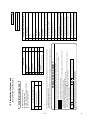
SERVICE MANUAL
INVERTER WALL MOUNTED TYPE
AND FLOOR STANDING TYPE
ROOM AIR-CONDITIONER
( Split system, air to air heat pump type )
Wall mounted type
SRK20ZIX-S
25ZIX-S
35ZIX-S
50ZIX-S
60ZIX-S
Floor standing type
SRF25ZIX-S
35ZIX-S
50ZIX-S
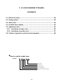
TABLE OF CONTENTS
1. WALL MOUNTED TYPE(SRK) .................................................................2
2. FLOOR STANDING TYPE(SRF) ............................................................45
3. MAINTENANCE DATA ...........................................................................69
3.1 Troubleshooting procedures for electrical equipment.................69
3.2 Servicing .........................................................................................90
4. REFRIGERANT PIPING INSTALLATION / SERVICING MANUAL
FOR AIR CONDITIONERS USING R410A .............................................91
4.1 Outline .............................................................................................91
4.2 Refrigerant piping installation .......................................................92
4.3 Installation, removal and servicing ...............................................98
4.4 Refrigerant recovery ....................................................................103
-
1-
1. WALL MOUNTED TYPE(SRK)
CONTENTS
1.1 Electrical wiring ....................................................................................3
1.2 Piping system .......................................................................................6
1.3 Noise level .............................................................................................7
1.4 Sensible heat capacity .......................................................................12
1.5 Application data ..................................................................................14
1.5.1 Installation of indoor unit ............................................................14
1.5.2 Installation of outdoor unit ..........................................................18
1.6 Outline of operation control by microcomputer ..............................33
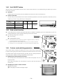
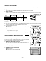
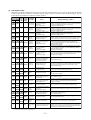
■ How
to read the model name
Example :
SR
K 50 Z
IX - S
Series code
Inverter type
Product capacity
Wall mounted type
Split type room air-conditioner
-
2-
V
V
6J
6J
-
*'#6
':%*#0)'4
5%$+-0'
+06'4(#%'-+6
6J
V
6J
%05
%0(
%0)
%0'
3-
,
4&
$- .
5㧛0
9*
;㧛) )
&+52.#;
9+4'.'554'%'+8'4
$#%-7259
7
(
8
#
8C
&5
24+06'&
%+4%7+6
$1#4&
㧛0
4&
$9*
;
$.
*'#6
':%*#0)'4
%07 %0;
%0:
%0:
6
(/+
/
.5
+/
5/
5/
./
./
5+)0#.9+4'
219'49+4'5
61176&11470+6
2QYGTUQWTEG
RJCUG8*\
/
/
/
/
/
0
+VGO
%0'%0;
(/+
5/
./
+/
6J
6J
6J
.5
&5
(
6
8C
$$.
4&
9*
;
;㧛)
$NCEM
$NWG
4GF
9JKVG
;GNNQY
;GNNQY㧛)TGGP
%QNQT/CTMU
/CTM
%QNQT
&GUETKRVKQP
%QPPGEVQT
(CPOQVQT
(NCROQVQT
.QWXGTOQVQT
+PNGVOQVQT
4QQOVGORUGPUQT
*GCVGZEJUGPUQT
*WOKFKV[UGPUQT㧔QPN[㧕
.KOKVUYKVEJ
&KQFGUVCEM
(WUG
6GTOKPCNDNQEM
8CTKUVQT
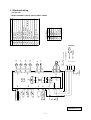
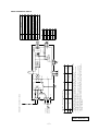
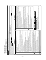
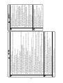
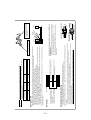
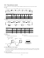
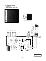
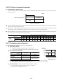
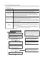
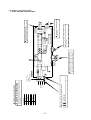
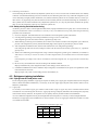
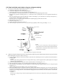
1.1 Electrical wiring
(1) Indoor unit
Models SRK20ZIX-S, 25ZIX-S, 35ZIX-S, 50ZIX-S, 60ZIX-S
RWA000Z215
5+)0#.9+4'
0
0
.
-
4-
/#:TWPPKPIEWTTGPV
㧔#㧕
2QYGTECDNGUK\G
㧔OO㧕
㧔;㧛)㧕)
VࠑVࠑ Vࠑ
5
6* 6* 6*
%06*
Vࠑ
%05
㧔4&㧕 %
01+5'
(+.6'4
㧔9*㧕 5+0
㧔$-㧕 4+0
%0''8
''8
/
ǾOOZ
ǾOO
(
8#
KPFQQTQWVFQQT
'CTVJYKTGUK\G
2QYGTECDNGNGPIVJ
YKTGUK\GZPWODGT
㧔O㧕
㧔OO㧕
㧔;㧛)㧕
8#
6 6
㧔;㧕
6JGURGEKHKECVKQPUUJQYPKPVJGCDQXGVCDNGCTGHQTWPKVUYKVJQWVJGCVGTU(QTWPKVUYKVJJGCVGTUTGHGT
VQVJGKPUVCNNCVKQPKPUVTWEVKQPUQTVJGEQPUVTWEVKQPKPUVTWEVKQPUQHVJGKPFQQTWPKV
5YKVEJIGCTQH%KTEWKVDTGCMGTECRCEKV[YJKEJKUECNEWNCVGFHTQO/#:QXGTEWTTGPVUJQWNFDGEJQUGP
CNQPIVJGTGIWNCVKQPUKPGCEJEQWPVT[
6JGECDNGURGEKHKECVKQPUCTGDCUGFQPVJGCUUWORVKQPVJCVCOGVCNQTRNCUVKEEQPFWKVKUWUGFYKVJPQ
OQTGVJCPVJTGGECDNGUEQPVCKPGFKPCEQPFWKVCPFCXQNVCIGFTQRKU(QTCPKPUVCNNCVKQPHCNNKPI
QWVUKFGQHVJGUGEQPFKVKQPURNGCUGHQNNQYVJGKPVGTPCNECDNKPITGIWNCVKQPU#FCRVKVVQVJGTGIWNCVKQP
KPGHHGEVKPGCEJEQWPVT[
/QFGN
2QYGTECDNGKPFQQTQWVFQQTEQPPGEVKPIYKTGU
219'49+4'5
=?
61+0&11470+6
6'4/+0#.
$.1%6
.
㧔14㧕
219'45174%'㨪㨺8*\㧛㨪8*\
8#
(
59+6%*+0)219'4
%+4%7+6
2#/
%+4%7+6
07
08
09
2
9
8
7
9 㧔$-㧕
8 㧔9*㧕
7 㧔4&㧕
%0(#0
(8#
8#
(
219'4
64#05+5614
29$#55;
(/Q
/
%/
㨪
/
6GTOKPCNDNQEM
*GCVGZEJCPIGTUGPUQT㧔QWVFQQTWPKV㧕
6
6*
;GNNQY
;GNNQY㧛)TGGP
;㧛)
9JKVG
4GF
1TCPIG
$NCEM
%QNQT
5QNGPQKFXCNXGHQTYC[XCNXG
;
9*
4&
14
$-
/CTM
5
&KUEJCTIGRKRGVGORUGPUQT
4GCEVQT
.
1WVFQQTCKTVGORUGPUQT
(CPOQVQT
(/Q
6*
'NGEVTKEGZRCPUKQPXCNXG㧔EQKN㧕
''8
6*
%QPPGEVQT
%0''8㨪5
&GUETKRVKQP
%QORTGUUQTOQVQT
+VGO
%/
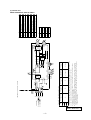
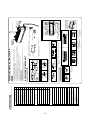
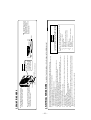
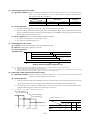
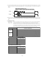
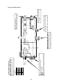
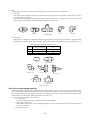
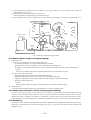
(2) Outdoor unit
Models SRC20ZIX-S, 25ZIX-S, 35ZIX-S
RWC000Z213
-
5-
5+)0#.9+4'
0
0
.
㧔;㧛)㧕
㧔9*㧕
㧔;㧛)㧕
8#
(75'
/#:TWPPKPIEWTTGPV
㧔#㧕
2QYGTECDNGUK\G
㧔OO㧕
%057$
㧔4&㧕 %
㧔$-㧕
㧔9*㧕 5
㧔9*㧕 5
㧔$-㧕 4
6*
Vࠑ
6*
Vࠑ
%06*
6*
Vࠑ
㧔;㧕
6
8#
(
ǾOOZ
ǾOO
''8
/
%0''8
29$#55;㧔/#+0㧕
#%6+8'
(+.6'4
70+6
KPFQQTQWVFQQT
'CTVJYKTGUK\G
2QYGTECDNGNGPIVJ
YKTGUK\GZPWODGT
㧔O㧕
㧔OO㧕
5
%0/#+0
5
51
41
㧔14㧕
6
6JGURGEKHKECVKQPUUJQYPKPVJGCDQXGVCDNGCTGHQTWPKVUYKVJQWVJGCVGTU(QTWPKVUYKVJJGCVGTUTGHGT
VQVJGKPUVCNNCVKQPKPUVTWEVKQPUQTVJGEQPUVTWEVKQPKPUVTWEVKQPUQHVJGKPFQQTWPKV
5YKVEJIGCTQH%KTEWKVDTGCMGTECRCEKV[YJKEJKUECNEWNCVGFHTQO/#:QXGTEWTTGPVUJQWNFDGEJQUGP
CNQPIVJGTGIWNCVKQPUKPGCEJEQWPVT[
6JGECDNGURGEKHKECVKQPUCTGDCUGFQPVJGCUUWORVKQPVJCVCOGVCNQTRNCUVKEEQPFWKVKUWUGFYKVJPQ
OQTGVJCPVJTGGECDNGUEQPVCKPGFKPCEQPFWKVCPFCXQNVCIGFTQRKU(QTCPKPUVCNNCVKQPHCNNKPI
QWVUKFGQHVJGUGEQPFKVKQPURNGCUGHQNNQYVJGKPVGTPCNECDNKPITGIWNCVKQPU#FCRVKVVQVJGTGIWNCVKQP
KPGHHGEVKPGCEJEQWPVT[
/QFGN
%05
㧔4&㧕
4176
㧔;㧛)㧕 )
㧔$4㧕
㧔9*㧕 5+0
㧔$-㧕 4+0
2QYGTECDNGKPFQQTQWVFQQTEQPPGEVKPIYKTGU
0
219'49+4'5
=?
61+0&11470+6
6
6'4/+0#.
$.1%-
6
(
29$#55;㧔57$㧕
8#
6'4/+0#.
$.1%-
.
8#
(
8#
59+6%*+0)219'4
%+4%7+6
(
219'45174%'㨪㨺8*\㧛㨪8*\
(8#
07
08
09
2
㧔9*㧕
㧔$-㧕
9
㧔4&㧕
8
7
%0(#0
9
8
7
219'4
64#05+5614
/
(/Q
/
%/
㨪
(CPOQVQT
4GCEVQT
6GTOKPCNDNQEM
*GCVGZEJCPIGTUGPUQT㧔QWVFQQTWPKV㧕
1WVFQQTCKTVGORUGPUQT
(/Q
.
6
6*
6*
9JKVG
;GNNQY
;GNNQY㧛)TGGP
;
;㧛)
4GF
1TCPIG
9*
4&
14
$TQYP
$NCEM
$4
%QNQT
$-
5QNGPQKFXCNXGHQTYC[XCNXG
/CTM
5
&KUEJCTIGRKRGVGORUGPUQT
'NGEVTKEGZRCPUKQPXCNXG㧔EQKN㧕
''8
6*
%QPPGEVQT
%0''8㨪5
&GUETKRVKQP
%QORTGUUQTOQVQT
+VGO
%/
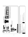
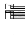
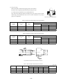
Models SRC50ZIX-S, 60ZIX-S
RWC000Z214
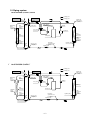
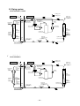
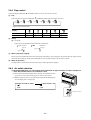
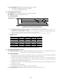
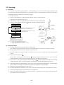
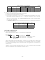
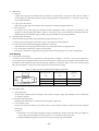
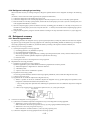
1.2 Piping system
Model SRK20ZIX-S, 25ZIX-S, 35ZIX-S
Cooling cycle
Indoor unit
Flare
connection
Heat
exchanger
sensor
(Th22)
Room temp.
sensor
(Th1)
Heating cycle
Outdoor unit
Outdoor air
temp. sensor
(TH2)
Service valve
(Gas)
Gas pipie
(φ9.52)
Discharge pipe
temp. sensor
(TH3)
Check joint
Muffler
4way valve
Muffler
Accumlator
Heat
exchanger
Heat
exchanger
Compressor
Heat
exchanger
sensor
(TH1)
Heat
exchanger
sensor
Liquid
(Th21)
pipe
(φ6.35)
Electronic
expansion valve
(EEV)
Capillary tube
Service valve
(Liquid)
Strainer
Flare connection
Capillary tube
Strainer
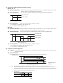
Models
SRK50ZIX-S,60ZIX-S
Model
SRK50ZIX-S, 60ZIX-S
Cooling cycle
Indoor unit
Room temp.
sensor
(Th1)
Flare
connection
Heat
exchanger
sensor
(Th22)
Gas pipie
(φ12.7)
Heating cycle
Outdoor unit
Outdoor air
temp. sensor
(TH2)
Service valve
(Gas)
Discharge pipe
temp. sensor
(TH3)
Check joint
Muffler
4way valve
Muffler
Heat
exchanger
Humidity
sensor
(Th3)
Heat
exchanger
Heat
exchanger
sensor
(Th21)
Liquid
pipe
(φ6.35)
Flare connection
Compressor
Electronic
expansion valve
(EEV)
Service valve
(Liquid)
Capillary tube
Strainer
-
6-
Capillary tube
Heat
exchanger
sensor
(TH1)
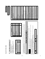
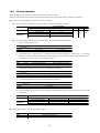
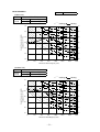
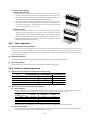
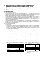
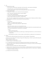
1.3 Noise level
Model SRK20ZIX-S
Condition
(Indoor Unit)
Model
SRK20ZIX-S
Cooling
39 dB(A)
Noise
Level
Heating
38 dB(A)
ISO-T1,JIS C9612
× ...... Cooling,
Heating
70
70
N70
60
60
Sound Pressure Level (dB)
(standard 2×10- 5 Pa )
N60
50
50
N5 0
40
40
N40
30
30
N3 0
20
20
N20
10
63
125
250
500
1000
Mid Octave Band frequency (Hz)
(Outdoor Unit)
Model
SRC20ZIX-S
Cooling
47 dB(A)
Noise
Level
Heating
47 dB(A)
2000
× ...... Cooling,
10
8000
4000
Heating
70
70
N70
60
60
Sound Pressure Level (dB)
(standard 2×10⁻⁵ Pa )
N60
50
50
N5 0
40
40
N4 0
30
30
N3 0
20
20
N2 0
10
63
125
250
500
1000
Mid Octave Band frequency (Hz)
-
7-
2000
4000
10
8000
Model SRK25ZIX-S
Condition
ISO-T1,JIS C9612
(Indoor Unit)
Model
SRK25ZIX-S
Cooling
41 dB(A)
Noise
Level
Heating
41 dB(A)
× ...... Cooling,
Heating
70
70
N70
60
60
Sound Pressure Level (dB)
(standard 2×10- 5 Pa )
N60
50
50
N 50
40
40
N 40
30
30
N 30
20
20
N20
10
63
125
250
500
1000
Mid Octave Band frequency (Hz)
2000
10
8000
4000
(Outdoor Unit)
Model
SRC25ZIX-S
Cooling
47 dB(A)
Noise
Level
Heating
47 dB(A)
× ...... Cooling,
Heating
70
70
N70
60
60
Sound Pressure Level (dB)
(standard 2×10⁻⁵ P a )
N60
50
50
N50
40
40
N40
30
30
N30
20
20
N20
10
63
125
250
500
1000
Mid Octave Band frequency (Hz)
-
8-
2000
4000
10
8000
Model SRK35ZIX-S
Condition
ISO-T1,JIS C9612
(Indoor Unit)
Model
SRK35ZIX-S
Cooling
43 dB(A)
Noise
Level
Heating
42 dB(A)
× ...... Cooling,
Heating
70
70
N 70
60
60
Sound Pressure Level (dB)
(standard 2×10- 5 Pa )
N 60
50
50
N50
40
40
N40
30
30
N30
20
20
N20
10
63
125
250
500
1000
Mid Octave Band frequency (Hz)
2000
10
8000
4000
(Outdoor Unit)
Model
SRC35ZIX-S
Cooling
50 dB(A)
Noise
Level
Heating
50 dB(A)
× ...... Cooling,
Heating
70
70
N70
60
60
Sound Pressure Level (dB)
(standard 2×10⁻⁵ P a)
N60
50
50
N50
40
40
N40
30
30
N30
20
20
N20
10
63
125
250
500
1000
Mid Octave Band frequency (Hz)
-
9-
2000
4000
10
8000
Model SRK50ZIX-S
Condition
ISO-T1,JIS C9612
(Indoor Unit)
Model
SRK50ZIX-S
Cooling
45 dB(A)
Noise
Level
Heating
45 dB(A)
× ...... Cooling,
Heating
70
70
N70
60
60
Sound Pressure Level (dB)
(standard 2×10- 5 Pa )
N60
50
50
N50
40
40
N40
30
30
N30
20
20
N20
10
63
125
250
500
1000
Mid Octave Band frequency (Hz)
2000
10
8000
4000
(Outdoor Unit)
Model
SRC50ZIX-S
Cooling
48 dB(A)
Noise
Level
Heating
48 dB(A)
× ...... Cooling,
Heating
70
70
N70
60
60
Sound Pressure Level (dB)
(standard 2×10⁻⁵ P a )
N60
50
50
N50
40
40
N40
30
30
N30
20
20
N20
10
63
125
250
500
1000
Mid Octave Band frequency (Hz)
-
10 -
2000
4000
10
8000
Model SRK60ZIX-S
Condition
ISO-T1,JIS C9612
(Indoor Unit)
Model
SRK60ZIX-S
Cooling
47 dB(A)
Noise
Level
Heating
45 dB(A)
× ...... Cooling,
Heating
70
70
N70
60
60
Sound Pressure Level (dB)
(standard 2×10- 5 Pa )
N60
50
50
N50
40
40
N40
30
30
N30
20
20
N20
10
63
125
250
500
1000
Mid Octave Band frequency (Hz)
2000
10
8000
4000
(Outdoor Unit)
Model
SRC60ZIX-S
Cooling
51 dB(A)
Noise
Level
Heating
51 dB(A)
× ...... Cooling,
Heating
70
70
N 70
60
60
Sound Pressure Level (dB)
(standard 2×10⁻⁵ P a )
N 60
50
50
N50
40
40
N40
30
30
N30
20
20
N20
10
63
125
250
500
1000
Mid Octave Band frequency (Hz)
-
11 -
2000
4000
10
8000
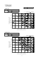
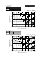
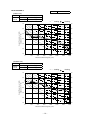
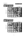
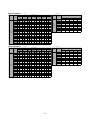
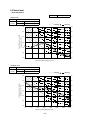
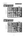
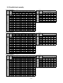
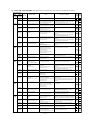
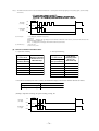
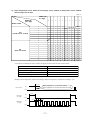
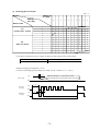
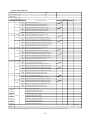
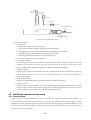
1.4 Sensible heat capacity
Model SRK20ZIX-S㩷㩷㩷㩷㩷㩷㩷㩷㩷㩷㩷㪚㫆㫆㫃㩷㪤㫆㪻㪼
㪟㪼㪸㫋㩷㪤㫆㪻㪼
㪠㫅㪻㫆㫆㫉㩷㪸㫀㫉㩷㫋㪼㫄㫇㩷
㪘㫀㫉㩷㪽㪄㫆㫎
㪟㫀
㪈㪈㪅㪌
㩿㫄㪊㪆㫄㫀㫅㪀
㪦㫌㫋㪻㫆㫆㫉
㪸㫀㫉㩷㫋㪼㫄㫇㪅
㪉㪈㷄㪛㪙
㪈㪋㷄㪮㪙
㪉㪊㷄㪛㪙
㪈㪍㷄㪮㪙
㪉㪍㷄㪛㪙
㪈㪏㷄㪮㪙
㪉㪎㷄㪛㪙
㪈㪐㷄㪮㪙
㪉㪏㷄㪛㪙
㪉㪇㷄㪮㪙
㪊㪈㷄㪛㪙
㪉㪉㷄㪮㪙
㪊㪊㷄㪛㪙
㪉㪋㷄㪮㪙
㪫㪚
㪪㪟㪚
㪫㪚
㪪㪟㪚
㪫㪚
㪪㪟㪚
㪫㪚
㪪㪟㪚
㪫㪚
㪪㪟㪚
㪫㪚
㪪㪟㪚
㪫㪚
㪪㪟㪚
㪈㪇
㪉㪅㪉㪌
㪉㪅㪈㪌㩷
㪉㪅㪊㪍㩷
㪉㪅㪈㪈㩷
㪉㪅㪋㪌㩷
㪉㪅㪉㪋㩷
㪉㪅㪋㪐㩷
㪉㪅㪉㪈㩷
㪉㪅㪌㪊㩷
㪉㪅㪈㪐㩷
㪉㪅㪍㪇㩷
㪉㪅㪊㪇㩷
㪉㪅㪍㪎㩷
㪉㪅㪉㪋㩷
㪈㪉
㪉㪅㪉㪈
㪉㪅㪈㪉㩷
㪉㪅㪊㪉㩷
㪉㪅㪇㪐㩷
㪉㪅㪋㪈㩷
㪉㪅㪉㪉㩷
㪉㪅㪋㪌㩷
㪉㪅㪉㪇㩷
㪉㪅㪌㪇㩷
㪉㪅㪈㪏㩷
㪉㪅㪌㪏㩷
㪉㪅㪉㪐㩷
㪉㪅㪍㪌㩷
㪉㪅㪉㪋㩷
㪈㪋
㪉㪅㪈㪎㩷
㪉㪅㪈㪇㩷
㪉㪅㪉㪏㩷
㪉㪅㪇㪎㩷
㪉㪅㪊㪏㩷
㪉㪅㪉㪈㩷
㪉㪅㪋㪉㩷
㪉㪅㪈㪐㩷
㪉㪅㪋㪎㩷
㪉㪅㪈㪎㩷
㪉㪅㪌㪌㩷
㪉㪅㪉㪏㩷
㪉㪅㪍㪉㩷
㪉㪅㪉㪊㩷
㪈㪍
㪉㪅㪈㪊㩷
㪉㪅㪇㪏㩷
㪉㪅㪉㪋㩷
㪉㪅㪇㪌㩷
㪉㪅㪊㪋㩷
㪉㪅㪈㪐㩷
㪉㪅㪊㪐㩷
㪉㪅㪈㪏㩷
㪉㪅㪋㪊㩷
㪉㪅㪈㪌㩷
㪉㪅㪌㪉㩷
㪉㪅㪉㪎㩷
㪉㪅㪌㪐㩷
㪉㪅㪉㪉㩷
㪈㪏
㪉㪅㪇㪏㩷
㪉㪅㪇㪍㩷
㪉㪅㪈㪐㩷
㪉㪅㪇㪊㩷
㪉㪅㪊㪇㩷
㪉㪅㪈㪎㩷
㪉㪅㪊㪌㩷
㪉㪅㪈㪍㩷
㪉㪅㪋㪇㩷
㪉㪅㪈㪋㩷
㪉㪅㪋㪐㩷
㪉㪅㪉㪍㩷
㪉㪅㪌㪍㩷
㪉㪅㪉㪈㩷
㪉㪇
㪉㪅㪇㪋㩷
㪉㪅㪇㪋㩷
㪉㪅㪈㪌㩷
㪉㪅㪇㪉㩷
㪉㪅㪉㪍㩷
㪉㪅㪈㪍㩷
㪉㪅㪊㪈㩷
㪉㪅㪈㪌㩷
㪉㪅㪊㪍㩷
㪉㪅㪈㪊㩷
㪉㪅㪋㪌㩷
㪉㪅㪉㪌㩷
㪉㪅㪌㪊㩷
㪉㪅㪉㪇㩷
㪉㪉
㪈㪅㪐㪐㩷
㪈㪅㪐㪐㩷
㪉㪅㪈㪇㩷
㪉㪅㪇㪇㩷
㪉㪅㪉㪉㩷
㪉㪅㪈㪌㩷
㪉㪅㪉㪏㩷
㪉㪅㪈㪊㩷
㪉㪅㪊㪉㩷
㪉㪅㪈㪉㩷
㪉㪅㪋㪉㩷
㪉㪅㪉㪊㩷
㪉㪅㪌㪇㩷
㪉㪅㪈㪐㩷
㪉㪋
㪈㪅㪐㪋㩷
㪈㪅㪐㪋㩷
㪉㪅㪇㪌㩷
㪈㪅㪐㪏㩷
㪉㪅㪈㪏㩷
㪉㪅㪈㪊㩷
㪉㪅㪉㪋㩷
㪉㪅㪈㪈㩷
㪉㪅㪉㪏㩷
㪉㪅㪈㪇㩷
㪉㪅㪊㪏㩷
㪉㪅㪉㪊㩷
㪉㪅㪋㪎㩷
㪉㪅㪈㪏㩷
㪉㪍
㪈㪅㪐㪇㩷
㪈㪅㪐㪇㩷
㪉㪅㪇㪈㩷
㪈㪅㪐㪎㩷
㪉㪅㪈㪋㩷
㪉㪅㪈㪈㩷
㪉㪅㪉㪇㩷
㪉㪅㪈㪇㩷
㪉㪅㪉㪋㩷
㪉㪅㪇㪏㩷
㪉㪅㪊㪌㩷
㪉㪅㪉㪈㩷
㪉㪅㪋㪊㩷
㪉㪅㪈㪏㩷
㪉㪏
㪈㪅㪏㪌㩷
㪈㪅㪏㪌㩷
㪈㪅㪐㪍㩷
㪈㪅㪐㪋㩷
㪉㪅㪇㪐㩷
㪉㪅㪇㪐㩷
㪉㪅㪈㪌㩷
㪉㪅㪇㪐㩷
㪉㪅㪉㪇㩷
㪉㪅㪇㪌㩷
㪉㪅㪊㪈㩷
㪉㪅㪉㪇㩷
㪉㪅㪋㪇㩷
㪉㪅㪈㪍㩷
㪊㪇
㪈㪅㪎㪐㩷
㪈㪅㪎㪐㩷
㪈㪅㪐㪇㩷
㪈㪅㪐㪇㩷
㪉㪅㪇㪌㩷
㪉㪅㪇㪌㩷
㪉㪅㪈㪈㩷
㪉㪅㪇㪌㩷
㪉㪅㪈㪍㩷
㪉㪅㪇㪋㩷
㪉㪅㪉㪎㩷
㪉㪅㪈㪐㩷
㪉㪅㪊㪍㩷
㪉㪅㪈㪌㩷
㪊㪉
㪈㪅㪎㪋㩷
㪈㪅㪎㪋㩷
㪈㪅㪏㪌㩷
㪈㪅㪏㪌㩷
㪉㪅㪇㪇㩷
㪉㪅㪇㪇㩷
㪉㪅㪇㪎㩷
㪉㪅㪇㪋㩷
㪉㪅㪈㪉㩷
㪉㪅㪇㪉㩷
㪉㪅㪉㪊㩷
㪉㪅㪈㪏㩷
㪉㪅㪊㪉㩷
㪉㪅㪈㪋㩷
㪊㪋
㪈㪅㪍㪐㩷
㪈㪅㪍㪐㩷
㪈㪅㪏㪇㩷
㪈㪅㪏㪇㩷
㪈㪅㪐㪌㩷
㪈㪅㪐㪌㩷
㪉㪅㪇㪉㩷
㪉㪅㪇㪉㩷
㪉㪅㪇㪎㩷
㪉㪅㪇㪈㩷
㪉㪅㪈㪐㩷
㪉㪅㪈㪍㩷
㪉㪅㪉㪏㩷
㪉㪅㪈㪊㩷
㪊㪌
㪈㪅㪍㪍㩷
㪈㪅㪍㪍㩷
㪈㪅㪎㪎㩷
㪈㪅㪎㪎㩷
㪈㪅㪐㪊㩷
㪈㪅㪐㪊㩷
㪉㪅㪇㪇㩷
㪉㪅㪇㪇㩷
㪉㪅㪇㪌㩷
㪉㪅㪇㪈㩷
㪉㪅㪈㪎㩷
㪉㪅㪈㪍㩷
㪉㪅㪉㪍㩷
㪉㪅㪈㪉
㪊㪍
㪈㪅㪍㪊㩷
㪈㪅㪍㪊㩷
㪈㪅㪎㪋㩷
㪈㪅㪎㪋㩷
㪈㪅㪐㪇㩷
㪈㪅㪐㪇㩷
㪈㪅㪐㪏㩷
㪈㪅㪐㪏㩷
㪉㪅㪇㪉㩷
㪉㪅㪇㪇㩷
㪉㪅㪈㪌㩷
㪉㪅㪈㪌㩷
㪉㪅㪉㪋㩷
㪉㪅㪈㪈
㪊㪏
㪈㪅㪌㪏㩷
㪈㪅㪌㪏㩷
㪈㪅㪍㪏㩷
㪈㪅㪍㪏㩷
㪈㪅㪏㪌㩷
㪈㪅㪏㪌㩷
㪈㪅㪐㪊㩷
㪈㪅㪐㪊㩷
㪈㪅㪐㪏㩷
㪈㪅㪐㪏㩷
㪉㪅㪈㪈㩷
㪉㪅㪈㪈㩷
㪉㪅㪉㪇㩷
㪉㪅㪈㪇
㪊㪐
㪈㪅㪌㪌㩷
㪈㪅㪌㪌㩷
㪈㪅㪍㪍㩷
㪈㪅㪍㪍㩷
㪈㪅㪏㪊㩷
㪈㪅㪏㪊㩷
㪈㪅㪐㪈㩷
㪈㪅㪐㪈㩷
㪈㪅㪐㪌㩷
㪈㪅㪐㪌㩷
㪉㪅㪇㪏㩷
㪉㪅㪇㪏㩷
㪉㪅㪈㪏㩷
㪉㪅㪈㪇
㪘㫀㫉㩷㪄㪽㫆㫎
㪟㫀
㪈㪉㪅㪇
㩿㫄㪊㪆㫄㫀㫅㪀
Model SRK25ZIX-S㩷㩷㩷㩷㩷㩷㩷㩷㩷㩷㩷㪚㫆㫆㫃㩷㪤㫆㪻㪼
㫀㫅㪻㫆㫆㫉㩷㪸㫀㫉㩷㫋㪼㫄㫇
㫆㫌㫋㪻㫆㫆㫉㩷
㪸㫀㫉㩷㫋㪼㫄㫇㪅
㪈㪍㷄㪛㪙
㪈㪏㷄㪛㪙
㪉㪇㷄㪛㪙
㪉㪉㷄㪛㪙
㪉㪋㷄㪛㪙
㪄㪈㪌㷄㪮㪙
㪈㪅㪌㪋㩷
㪈㪅㪌㪈㩷
㪈㪅㪋㪎㩷
㪈㪅㪋㪋㩷
㪈㪅㪋㪈㩷
㪄㪈㪇㷄㪮㪙
㪈㪅㪎㪋㩷
㪈㪅㪎㪈㩷
㪈㪅㪍㪐㩷
㪈㪅㪍㪋㩷
㪈㪅㪍㪈㩷
㪄㪌㷄㪮㪙
㪈㪅㪏㪐㩷
㪈㪅㪏㪍㩷
㪈㪅㪏㪉㩷
㪈㪅㪏㪇㩷
㪈㪅㪎㪎㩷
㪇㷄㪮㪙
㪈㪅㪐㪏㩷
㪈㪅㪐㪌㩷
㪈㪅㪐㪈㩷
㪈㪅㪏㪐㩷
㪈㪅㪏㪍㩷
㪌㷄㪮㪙
㪉㪅㪌㪉㩷
㪉㪅㪋㪐㩷
㪉㪅㪋㪏㩷
㪉㪅㪋㪊㩷
㪉㪅㪊㪐㩷
㪍㷄㪮㪙
㪉㪅㪌㪍㩷
㪉㪅㪌㪊㩷
㪉㪅㪌㪇㩷
㪉㪅㪋㪎㩷
㪉㪅㪋㪋㩷
㪈㪇㷄㪮㪙
㪉㪅㪎㪉㩷
㪉㪅㪍㪐㩷
㪉㪅㪍㪏㩷
㪉㪅㪍㪋㩷
㪉㪅㪍㪈㩷
㪈㪌㷄㪮㪙
㪉㪅㪐㪍㩷
㪉㪅㪐㪊㩷
㪉㪅㪐㪈㩷
㪉㪅㪏㪏㩷
㪉㪅㪏㪌㩷
㪉㪇㷄㪮㪙
㪊㪅㪈㪏㩷
㪊㪅㪈㪌㩷
㪊㪅㪈㪋㩷
㪊㪅㪈㪇㩷
㪊㪅㪇㪏㩷
㪟㪼㪸㫋㩷㪤㫆㪻㪼
㪠㫅㪻㫆㫆㫉㩷㪸㫀㫉㩷㫋㪼㫄㫇
㪘㫀㫉㩷㪄
㪽㫆㫎
㪟㫀
㪈㪉㪅㪌
㪊
㩿㫄 㪆㫄㫀㫅㪀
㪦㫌㫋㪻㫆㫆㫉
㪸㫀㫉㩷㫋㪼㫄㫇㪅
㪉㪈㷄㪛㪙
㪈㪋㷄㪮㪙
㪉㪊㷄㪛㪙
㪈㪍㷄㪮㪙
㪉㪍㷄㪛㪙
㪈㪏㷄㪮㪙
㪉㪎㷄㪛㪙
㪈㪐㷄㪮㪙
㪉㪏㷄㪛㪙
㪉㪇㷄㪮㪙
㪊㪈㷄㪛㪙
㪉㪉㷄㪮㪙
㪊㪊㷄㪛㪙
㪉㪋㷄㪮㪙
㪫㪚
㪪㪟㪚
㪫㪚
㪪㪟㪚
㪫㪚
㪪㪟㪚
㪫㪚
㪪㪟㪚
㪫㪚
㪪㪟㪚
㪫㪚
㪪㪟㪚
㪫㪚
㪪㪟㪚
㪈㪇
㪉㪅㪏㪎
㪉㪅㪍㪐㩷
㪊㪅㪇㪈㩷
㪉㪅㪍㪌㩷
㪊㪅㪈㪉㩷
㪉㪅㪏㪇
㪊㪅㪈㪎
㪉㪅㪎㪎
㪊㪅㪉㪊
㪉㪅㪎㪋
㪊㪅㪊㪉
㪉㪅㪏㪏
㪊㪅㪋㪈
㪉㪅㪏㪈
㪈㪉
㪉㪅㪏㪉
㪉㪅㪍㪎㩷
㪉㪅㪐㪍㩷
㪉㪅㪍㪊㩷
㪊㪅㪇㪎㩷
㪉㪅㪎㪏
㪊㪅㪈㪊
㪉㪅㪎㪌
㪊㪅㪈㪐
㪉㪅㪎㪊
㪊㪅㪉㪏
㪉㪅㪏㪍
㪊㪅㪊㪏
㪉㪅㪏㪇
㪈㪋
㪉㪅㪎㪎
㪉㪅㪍㪋㩷
㪉㪅㪐㪇㩷
㪉㪅㪍㪈㩷
㪊㪅㪇㪊㩷
㪉㪅㪎㪍
㪊㪅㪇㪐
㪉㪅㪎㪋
㪊㪅㪈㪋
㪉㪅㪍㪐
㪊㪅㪉㪌
㪉㪅㪏㪌
㪊㪅㪊㪋
㪉㪅㪎㪐
㪈㪍
㪉㪅㪎㪈㩷
㪉㪅㪍㪈㩷
㪉㪅㪏㪌㩷
㪉㪅㪌㪏㩷
㪉㪅㪐㪏㩷
㪉㪅㪎㪋
㪊㪅㪇㪋
㪉㪅㪎㪇
㪊㪅㪈㪇
㪉㪅㪍㪏
㪊㪅㪉㪈
㪉㪅㪏㪋
㪊㪅㪊㪈
㪉㪅㪎㪏
㪈㪏
㪉㪅㪍㪍㩷
㪉㪅㪌㪐㩷
㪉㪅㪏㪇㩷
㪉㪅㪌㪍㩷
㪉㪅㪐㪊㩷
㪉㪅㪎㪈
㪊㪅㪇㪇
㪉㪅㪍㪐
㪊㪅㪇㪌
㪉㪅㪍㪍
㪊㪅㪈㪎
㪉㪅㪏㪉
㪊㪅㪉㪎
㪉㪅㪎㪎
㪉㪇
㪉㪅㪍㪇㩷
㪉㪅㪌㪍㩷
㪉㪅㪎㪋㩷
㪉㪅㪌㪋㩷
㪉㪅㪏㪏㩷
㪉㪅㪍㪐
㪉㪅㪐㪌
㪉㪅㪍㪎
㪊㪅㪇㪈
㪉㪅㪍㪌
㪊㪅㪈㪊
㪉㪅㪏㪈
㪊㪅㪉㪊
㪉㪅㪎㪌
㪉㪉
㪉㪅㪌㪋㩷
㪉㪅㪌㪋㩷
㪉㪅㪍㪏㩷
㪉㪅㪌㪈㩷
㪉㪅㪏㪊㩷
㪉㪅㪍㪎
㪉㪅㪐㪇
㪉㪅㪍㪌
㪉㪅㪐㪍
㪉㪅㪍㪊
㪊㪅㪇㪏
㪉㪅㪏㪇
㪊㪅㪈㪐
㪉㪅㪎㪋
㪉㪋
㪉㪅㪋㪏㩷
㪉㪅㪋㪏㩷
㪉㪅㪍㪉㩷
㪉㪅㪋㪏㩷
㪉㪅㪎㪏㩷
㪉㪅㪍㪌
㪉㪅㪏㪌
㪉㪅㪍㪋
㪉㪅㪐㪈
㪉㪅㪍㪈
㪊㪅㪇㪋
㪉㪅㪎㪏
㪊㪅㪈㪌
㪉㪅㪎㪉
㪉㪍
㪉㪅㪋㪉㩷
㪉㪅㪋㪉㩷
㪉㪅㪌㪍㩷
㪉㪅㪋㪍㩷
㪉㪅㪎㪉㩷
㪉㪅㪍㪊
㪉㪅㪏㪇
㪉㪅㪍㪉
㪉㪅㪏㪍
㪉㪅㪍㪇
㪉㪅㪐㪐
㪉㪅㪎㪍
㪊㪅㪈㪇
㪉㪅㪎㪈
㪉㪏
㪉㪅㪊㪌㩷
㪉㪅㪊㪌
㪉㪅㪋㪐㩷
㪉㪅㪋㪊㩷
㪉㪅㪍㪎㩷
㪉㪅㪍㪉
㪉㪅㪎㪌
㪉㪅㪍㪇
㪉㪅㪏㪈
㪉㪅㪌㪏
㪉㪅㪐㪌
㪉㪅㪎㪌
㪊㪅㪇㪍
㪉㪅㪎㪇
㪊㪇
㪉㪅㪉㪐㩷
㪉㪅㪉㪐
㪉㪅㪋㪊㩷
㪉㪅㪋㪇㩷
㪉㪅㪍㪈㩷
㪉㪅㪌㪐
㪉㪅㪍㪐
㪉㪅㪌㪏
㪉㪅㪎㪌
㪉㪅㪌㪍
㪉㪅㪐㪇
㪉㪅㪎㪋
㪊㪅㪇㪈
㪉㪅㪍㪐
㪊㪉
㪉㪅㪉㪉㩷
㪉㪅㪉㪉㩷
㪉㪅㪊㪍㩷
㪉㪅㪊㪍㩷
㪉㪅㪌㪌㩷
㪉㪅㪌㪌
㪉㪅㪍㪋
㪉㪅㪌㪍
㪉㪅㪎㪇
㪉㪅㪌㪋
㪉㪅㪏㪌
㪉㪅㪎㪈
㪉㪅㪐㪍
㪉㪅㪍㪎
㪊㪋
㪉㪅㪈㪌㩷
㪉㪅㪈㪌㩷
㪉㪅㪉㪐㩷
㪉㪅㪉㪐㩷
㪉㪅㪋㪐㩷
㪉㪅㪋㪐
㪉㪅㪌㪏
㪉㪅㪌㪌
㪉㪅㪍㪋
㪉㪅㪌㪊
㪉㪅㪎㪐
㪉㪅㪎㪇
㪉㪅㪐㪈
㪉㪅㪍㪌
㪊㪌
㪉㪅㪈㪉㩷
㪉㪅㪈㪉㩷
㪉㪅㪉㪍㩷
㪉㪅㪉㪍㩷
㪉㪅㪋㪍
㪉㪅㪋㪍
㪉㪅㪌㪌
㪉㪅㪌㪊
㪉㪅㪍㪈
㪉㪅㪌㪉
㪉㪅㪎㪎
㪉㪅㪍㪐
㪉㪅㪏㪐
㪉㪅㪍㪌
㪊㪍
㪉㪅㪇㪏㩷
㪉㪅㪇㪏
㪉㪅㪉㪉㩷
㪉㪅㪉㪉㩷
㪉㪅㪋㪊
㪉㪅㪋㪊
㪉㪅㪌㪉
㪉㪅㪌㪉
㪉㪅㪌㪏
㪉㪅㪌㪈
㪉㪅㪎㪋
㪉㪅㪍㪏
㪉㪅㪏㪍
㪉㪅㪍㪋
㪊㪏
㪉㪅㪇㪈㩷
㪉㪅㪇㪈㩷
㪉㪅㪈㪌㩷
㪉㪅㪈㪌㩷
㪉㪅㪊㪍
㪉㪅㪊㪍
㪉㪅㪋㪍
㪉㪅㪋㪍
㪉㪅㪌㪉
㪉㪅㪋㪐
㪉㪅㪍㪐
㪉㪅㪍㪎
㪉㪅㪏㪈
㪉㪅㪍㪇
㪊㪐
㪈㪅㪐㪎㩷
㪈㪅㪐㪎㩷
㪉㪅㪈㪈㩷
㪉㪅㪈㪈㩷
㪉㪅㪊㪊
㪉㪅㪊㪊
㪉㪅㪋㪊
㪉㪅㪋㪊
㪉㪅㪋㪐
㪉㪅㪋㪏
㪉㪅㪍㪍
㪉㪅㪍㪊
㪉㪅㪎㪏
㪉㪅㪌㪐
㪘㫀㫉㩷㪽㪄㫆㫎
㪟㫀
㪈㪊㪅㪇
㩿㫄㪊㪆㫄㫀㫅㪀
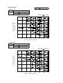
Model SRK35ZIX-S㩷㩷㩷㩷㩷㩷㩷㩷㩷㩷㩷㪚㫆㫆㫃㩷㪤㫆㪻㪼
㫀㫅㪻㫆㫆㫉㩷㪸㫀㫉㩷㫋㪼㫄㫇
㫆㫌㫋㪻㫆㫆㫉㩷
㪸㫀㫉㩷㫋㪼㫄㫇㪅
㪈㪍㷄㪛㪙
㪈㪏㷄㪛㪙
㪉㪇㷄㪛㪙
㪉㪉㷄㪛㪙
㪉㪋㷄㪛㪙
㪄㪈㪌㷄㪮㪙
㪈㪅㪐㪊㩷
㪈㪅㪏㪏㩷
㪈㪅㪏㪋㩷
㪈㪅㪏㪇㩷
㪈㪅㪎㪍㩷
㪄㪈㪇㷄㪮㪙
㪉㪅㪈㪏㩷
㪉㪅㪈㪋㩷
㪉㪅㪈㪈㩷
㪉㪅㪇㪍㩷
㪉㪅㪇㪉㩷
㪄㪌㷄㪮㪙
㪉㪅㪊㪍㩷
㪉㪅㪊㪊㩷
㪉㪅㪉㪏㩷
㪉㪅㪉㪌㩷
㪉㪅㪉㪉㩷
㪇㷄㪮㪙
㪉㪅㪋㪎㩷
㪉㪅㪋㪋㩷
㪉㪅㪋㪇㩷
㪉㪅㪊㪎㩷
㪉㪅㪊㪊㩷
㪌㷄㪮㪙
㪊㪅㪈㪌㩷
㪊㪅㪈㪉㩷
㪊㪅㪈㪇㩷
㪊㪅㪇㪋㩷
㪉㪅㪐㪐㩷
㪍㷄㪮㪙
㪊㪅㪉㪇㩷
㪊㪅㪈㪎㩷
㪊㪅㪈㪊㩷
㪊㪅㪇㪐㩷
㪊㪅㪇㪌㩷
㪈㪇㷄㪮㪙
㪊㪅㪋㪇㩷
㪊㪅㪊㪎㩷
㪊㪅㪊㪌㩷
㪊㪅㪊㪇㩷
㪊㪅㪉㪎㩷
㪈㪌㷄㪮㪙
㪊㪅㪎㪇㩷
㪊㪅㪍㪎㩷
㪊㪅㪍㪌㩷
㪊㪅㪍㪈㩷
㪊㪅㪌㪎㩷
㪉㪇㷄㪮㪙
㪊㪅㪐㪏㩷
㪊㪅㪐㪌㩷
㪊㪅㪐㪊㩷
㪊㪅㪏㪏㩷
㪊㪅㪏㪌㩷
㪈㪍㷄㪛㪙
㪈㪏㷄㪛㪙
㪉㪇㷄㪛㪙
㪉㪉㷄㪛㪙
㪉㪋㷄㪛㪙
㪄㪈㪌㷄㪮㪙
㪉㪅㪍㪌㩷
㪉㪅㪌㪐㩷
㪉㪅㪌㪊㩷
㪉㪅㪋㪏㩷
㪉㪅㪋㪉㩷
㪄㪈㪇㷄㪮㪙
㪉㪅㪐㪐㩷
㪉㪅㪐㪋㩷
㪉㪅㪐㪇㩷
㪉㪅㪏㪊㩷
㪉㪅㪎㪎㩷
㪄㪌㷄㪮㪙
㪊㪅㪉㪋㩷
㪊㪅㪉㪇㩷
㪊㪅㪈㪊㩷
㪊㪅㪈㪇㩷
㪊㪅㪇㪌㩷
㪇㷄㪮㪙
㪊㪅㪋㪇㩷
㪊㪅㪊㪌㩷
㪊㪅㪉㪐㩷
㪊㪅㪉㪌㩷
㪊㪅㪉㪇㩷
㪌㷄㪮㪙
㪋㪅㪊㪊㩷
㪋㪅㪉㪏㩷
㪋㪅㪉㪍㩷
㪋㪅㪈㪎㩷
㪋㪅㪈㪈㩷
㪍㷄㪮㪙
㪋㪅㪋㪇㩷
㪋㪅㪊㪌㩷
㪋㪅㪊㪇㩷
㪋㪅㪉㪌㩷
㪋㪅㪈㪐㩷
㪈㪇㷄㪮㪙
㪋㪅㪍㪏㩷
㪋㪅㪍㪊㩷
㪋㪅㪍㪇㩷
㪋㪅㪌㪋㩷
㪋㪅㪋㪐㩷
㪈㪌㷄㪮㪙
㪌㪅㪇㪐㩷
㪌㪅㪇㪋㩷
㪌㪅㪇㪈㩷
㪋㪅㪐㪌㩷
㪋㪅㪐㪈㩷
㪉㪇㷄㪮㪙
㪌㪅㪋㪎㩷
㪌㪅㪋㪉㩷
㪌㪅㪋㪇㩷
㪌㪅㪊㪋㩷
㪌㪅㪉㪐㩷
㪟㪼㪸㫋㩷㪤㫆㪻㪼
㪠㫅㪻㫆㫆㫉㩷㪸㫀㫉㩷㫋㪼㫄㫇
㪘㫀㫉㩷㪄
㪽㫆㫎
㪟㫀
㪈㪊㪅㪌
㩿㫄㪊㪆㫄㫀㫅㪀
㪦㫌㫋㪻㫆㫆㫉
㪸㫀㫉㩷㫋㪼㫄㫇㪅
㪉㪈㷄㪛㪙
㪈㪋㷄㪮㪙
㪉㪊㷄㪛㪙
㪈㪍㷄㪮㪙
㪉㪍㷄㪛㪙
㪈㪏㷄㪮㪙
㪉㪎㷄㪛㪙
㪈㪐㷄㪮㪙
㪉㪏㷄㪛㪙
㪉㪇㷄㪮㪙
㪊㪈㷄㪛㪙
㪉㪉㷄㪮㪙
㪊㪊㷄㪛㪙
㪉㪋㷄㪮㪙
㪫㪚
㪪㪟㪚
㪫㪚
㪪㪟㪚
㪫㪚
㪪㪟㪚
㪫㪚
㪪㪟㪚
㪫㪚
㪪㪟㪚
㪫㪚
㪪㪟㪚
㪫㪚
㪪㪟㪚
㪈㪇
㪊㪅㪐㪋
㪊㪅㪋㪎
㪋㪅㪈㪊
㪊㪅㪋㪉㩷
㪋㪅㪉㪏㩷
㪊㪅㪌㪐㩷
㪋㪅㪊㪌㩷
㪊㪅㪌㪌㩷
㪋㪅㪋㪊㩷
㪊㪅㪌㪈㩷
㪋㪅㪌㪍㩷
㪊㪅㪍㪍㩷
㪋㪅㪍㪏㩷
㪊㪅㪌㪌㩷
㪈㪉
㪊㪅㪏㪎
㪊㪅㪋㪋
㪋㪅㪇㪍
㪊㪅㪊㪐㩷
㪋㪅㪉㪉㩷
㪊㪅㪌㪍㩷
㪋㪅㪉㪐㩷
㪊㪅㪌㪊㩷
㪋㪅㪊㪎㩷
㪊㪅㪋㪐㩷
㪋㪅㪌㪈㩷
㪊㪅㪍㪌㩷
㪋㪅㪍㪊㩷
㪊㪅㪌㪊㩷
㪈㪋
㪊㪅㪏㪇
㪊㪅㪋㪇
㪊㪅㪐㪐
㪊㪅㪊㪍㩷
㪋㪅㪈㪍㩷
㪊㪅㪌㪋㩷
㪋㪅㪉㪋㩷
㪊㪅㪌㪇㩷
㪋㪅㪊㪈㩷
㪊㪅㪋㪎㩷
㪋㪅㪋㪍㩷
㪊㪅㪍㪈㩷
㪋㪅㪌㪐㩷
㪊㪅㪌㪉㩷
㪈㪍
㪊㪅㪎㪉
㪊㪅㪊㪎
㪊㪅㪐㪈
㪊㪅㪊㪉㩷
㪋㪅㪇㪐㩷
㪊㪅㪌㪈㩷
㪋㪅㪈㪏㩷
㪊㪅㪋㪏㩷
㪋㪅㪉㪌㩷
㪊㪅㪋㪋㩷
㪋㪅㪋㪇㩷
㪊㪅㪌㪐㩷
㪋㪅㪌㪋㩷
㪊㪅㪌㪇㩷
㪈㪏
㪊㪅㪍㪌
㪊㪅㪊㪊
㪊㪅㪏㪋
㪊㪅㪉㪐㩷
㪋㪅㪇㪊㩷
㪊㪅㪋㪏㩷
㪋㪅㪈㪈㩷
㪊㪅㪋㪌㩷
㪋㪅㪈㪐㩷
㪊㪅㪋㪉㩷
㪋㪅㪊㪌㩷
㪊㪅㪌㪎㩷
㪋㪅㪋㪐㩷
㪊㪅㪋㪐㩷
㪉㪇
㪊㪅㪌㪎
㪊㪅㪊㪇
㪊㪅㪎㪍
㪊㪅㪉㪌㩷
㪊㪅㪐㪍㩷
㪊㪅㪋㪍㩷
㪋㪅㪇㪌㩷
㪊㪅㪋㪊㩷
㪋㪅㪈㪊㩷
㪊㪅㪊㪐㩷
㪋㪅㪉㪐㩷
㪊㪅㪌㪌㩷
㪋㪅㪋㪊㩷
㪊㪅㪋㪎㩷
㪉㪉
㪊㪅㪋㪐
㪊㪅㪉㪍
㪊㪅㪍㪏㩷
㪊㪅㪉㪉㩷
㪊㪅㪏㪐㩷
㪊㪅㪋㪊㩷
㪊㪅㪐㪏㩷
㪊㪅㪋㪇㩷
㪋㪅㪇㪍㩷
㪊㪅㪊㪎㩷
㪋㪅㪉㪊㩷
㪊㪅㪌㪊㩷
㪋㪅㪊㪏㩷
㪊㪅㪋㪌㩷
㪉㪋
㪊㪅㪋㪇
㪊㪅㪉㪉
㪊㪅㪌㪐㩷
㪊㪅㪈㪐㩷
㪊㪅㪏㪈㩷
㪊㪅㪋㪇㩷
㪊㪅㪐㪈㩷
㪊㪅㪊㪏㩷
㪊㪅㪐㪐㩷
㪊㪅㪊㪌㩷
㪋㪅㪈㪎㩷
㪊㪅㪌㪈㩷
㪋㪅㪊㪉㩷
㪊㪅㪋㪋㩷
㪉㪍
㪊㪅㪊㪉
㪊㪅㪈㪏
㪊㪅㪌㪈㩷
㪊㪅㪈㪋㩷
㪊㪅㪎㪋㩷
㪊㪅㪊㪎㩷
㪊㪅㪏㪋㩷
㪊㪅㪊㪌㩷
㪊㪅㪐㪉㩷
㪊㪅㪊㪉㩷
㪋㪅㪈㪈㩷
㪊㪅㪋㪐㩷
㪋㪅㪉㪍㩷
㪊㪅㪋㪉㩷
㪉㪏
㪊㪅㪉㪊
㪊㪅㪈㪋
㪊㪅㪋㪉㩷
㪊㪅㪈㪈㩷
㪊㪅㪍㪍㩷
㪊㪅㪊㪋㩷
㪊㪅㪎㪎㩷
㪊㪅㪊㪉㩷
㪊㪅㪏㪌㩷
㪊㪅㪊㪇㩷
㪋㪅㪇㪋㩷
㪊㪅㪋㪎㩷
㪋㪅㪉㪇㩷
㪊㪅㪋㪇㩷
㪊㪇
㪊㪅㪈㪋
㪊㪅㪈㪇
㪊㪅㪊㪊㩷
㪊㪅㪇㪎㩷
㪊㪅㪌㪏㩷
㪊㪅㪊㪈㩷
㪊㪅㪎㪇㩷
㪊㪅㪉㪐㩷
㪊㪅㪎㪏㩷
㪊㪅㪉㪍㩷
㪊㪅㪐㪏㩷
㪊㪅㪋㪌㩷
㪋㪅㪈㪊㩷
㪊㪅㪊㪏㩷
㪊㪉
㪊㪅㪇㪌
㪊㪅㪇㪌
㪊㪅㪉㪋㩷
㪊㪅㪇㪊㩷
㪊㪅㪌㪇㩷
㪊㪅㪉㪎㩷
㪊㪅㪍㪉㩷
㪊㪅㪉㪍㩷
㪊㪅㪎㪇㩷
㪊㪅㪉㪋㩷
㪊㪅㪐㪈㩷
㪊㪅㪋㪊㩷
㪋㪅㪇㪍㩷
㪊㪅㪊㪍㩷
㪊㪋
㪉㪅㪐㪌
㪉㪅㪐㪌
㪊㪅㪈㪋㩷
㪊㪅㪇㪇㩷
㪊㪅㪋㪈㩷
㪊㪅㪉㪋㩷
㪊㪅㪌㪋㩷
㪊㪅㪉㪊㩷
㪊㪅㪍㪉㩷
㪊㪅㪉㪈㩷
㪊㪅㪏㪋㩷
㪊㪅㪋㪇㩷
㪋㪅㪇㪇㩷
㪊㪅㪊㪋㩷
㪊㪌
㪉㪅㪐㪈
㪉㪅㪐㪈
㪊㪅㪈㪇㩷
㪉㪅㪐㪏㩷
㪊㪅㪊㪎㩷
㪊㪅㪉㪊㩷
㪊㪅㪌㪇㩷
㪊㪅㪉㪉㩷
㪊㪅㪌㪏㩷
㪊㪅㪉㪇㩷
㪊㪅㪏㪇㩷
㪊㪅㪊㪐㩷
㪊㪅㪐㪍㩷
㪊㪅㪊㪊㩷
㪊㪍
㪉㪅㪏㪍
㪉㪅㪏㪍
㪊㪅㪇㪌㩷
㪉㪅㪐㪍㩷
㪊㪅㪊㪊㩷
㪊㪅㪉㪈㩷
㪊㪅㪋㪍㩷
㪊㪅㪉㪇㩷
㪊㪅㪌㪋㩷
㪊㪅㪈㪏㩷
㪊㪅㪎㪍㩷
㪊㪅㪊㪏㩷
㪊㪅㪐㪉㩷
㪊㪅㪊㪉㩷
㪊㪏
㪉㪅㪎㪍
㪉㪅㪎㪍
㪉㪅㪐㪌㩷
㪉㪅㪐㪈㩷
㪊㪅㪉㪋㩷
㪊㪅㪈㪏㩷
㪊㪅㪊㪏㩷
㪊㪅㪈㪏㩷
㪊㪅㪋㪍㩷
㪊㪅㪈㪌㩷
㪊㪅㪍㪐㩷
㪊㪅㪊㪍㩷
㪊㪅㪏㪌㩷
㪊㪅㪊㪇㩷
㪊㪐
㪉㪅㪎㪈
㪉㪅㪎㪈
㪉㪅㪐㪇㩷
㪉㪅㪏㪐㩷
㪊㪅㪉㪇㩷
㪊㪅㪈㪍㩷
㪊㪅㪊㪊㩷
㪊㪅㪈㪍㩷
㪊㪅㪋㪉㩷
㪊㪅㪈㪋㩷
㪊㪅㪍㪌㩷
㪊㪅㪊㪋㩷
㪊㪅㪏㪈㩷
㪊㪅㪉㪐
-
12 -
㪘㫀㫉㩷㪄㪽㫆㫎
㪟㫀
㪈㪋㪅㪇
㪊
㩿㫄 㪆㫄㫀㫅㪀
㫀㫅㪻㫆㫆㫉㩷㪸㫀㫉㩷㫋㪼㫄㫇
㫆㫌㫋㪻㫆㫆㫉㩷
㪸㫀㫉㩷㫋㪼㫄㫇㪅
㧖
Model SRK50ZIX-S
Cool Mode
Heat Mode
Indoor air temp
Air flow
Hi
13.5
(m3/min)
Outdoor
air temp.
21˚CDB
14˚CWB
23˚CDB
16˚CWB
26˚CDB
18˚CWB
27˚CDB
19˚CWB
28˚CDB
20˚CWB
31˚CDB
22˚CWB
33˚CDB
24˚CWB
TC
SHC
TC
SHC
TC
SHC
TC
SHC
TC
SHC
TC
SHC
TC
SHC
10
5.63
4.27
5.90
4.20
6.11
4.32
6.22
4.26
6.32
4.21
6.51
4.30
6.69
4.17
12
5.53
4.22
5.80
4.15
6.03
4.29
6.14
4.23
6.25
4.18
6.44
4.27
6.62
4.15
14
5.43
4.17
5.70
4.10
5.94
4.25
6.05
4.20
6.16
4.14
6.37
4.25
6.55
4.12
16
5.32
4.11
5.59
4.05
5.85
4.21
5.96
4.16
6.08
4.10
6.29
4.22
6.48
4.10
18
5.21
4.05
5.48
3.99
5.75
4.16
5.88
4.12
5.99
4.07
6.21
4.19
6.41
4.08
20
5.10
3.99
5.37
3.94
5.65
4.12
5.78
4.08
5.90
4.03
6.13
4.16
6.33
4.05
22
4.98
3.93
5.25
3.89
5.55
4.07
5.69
4.04
5.80
3.99
6.05
4.13
6.25
4.02
24
4.86
3.87
5.14
3.83
5.45
4.03
5.59
4.00
5.71
3.95
5.96
4.10
6.17
3.99
26
4.74
3.81
5.01
3.77
5.34
3.98
5.49
3.95
5.61
3.91
5.87
4.07
6.08
3.97
28
4.61
3.75
4.89
3.71
5.23
3.93
5.39
3.91
5.50
3.87
5.78
4.03
5.99
3.93
30
4.49
3.68
4.76
3.65
5.11
3.88
5.28
3.86
5.40
3.82
5.68
3.99
5.90
3.90
32
4.35
3.62
4.63
3.59
5.00
3.83
5.17
3.82
5.29
3.78
5.58
3.96
5.81
3.87
34
4.22
3.55
4.49
3.53
4.88
3.78
5.06
3.78
5.18
3.74
5.48
3.92
5.71
3.83
35
4.15
3.52
4.42
3.50
4.82
3.75
5.00
3.75
5.12
3.71
5.43
3.91
5.66
3.82
36
4.08
3.48
4.35
3.45
4.76
3.73
4.94
3.72
5.06
3.69
5.37
3.88
5.61
3.80
38
3.94
3.41
4.21
3.39
4.63
3.67
4.82
3.68
4.94
3.65
5.27
3.85
5.50
3.77
39
3.87
3.38
4.14
3.36
4.57
3.65
4.76
3.65
4.88
3.62
5.21
3.83
5.45
3.75
Model SRK60ZIX-S
Air flow
Hi
16.5
(m3/min)
Cool Mode
indoor air temp
outdoor
air temp.
16˚CDB
18˚CDB
20˚CDB
22˚CDB
24˚CDB
-15˚CWB
3.69
3.61
3.53
3.45
3.38
-10˚CWB
4.18
4.10
4.05
3.95
3.86
-5˚CWB
4.52
4.46
4.37
4.32
4.25
0˚CWB
4.74
4.67
4.59
4.54
4.47
5˚CWB
6.04
5.97
5.94
5.82
5.74
6˚CWB
6.14
6.07
6.00
5.92
5.85
10˚CWB
6.52
6.46
6.42
6.34
6.27
15˚CWB
7.10
7.04
6.99
6.91
6.85
20˚CWB
7.63
7.57
7.53
7.45
7.39
Heat Mode
Indoor air temp
Air flow
Hi
14.5
3
(m /min)
Outdoor
air temp.
21˚CDB
14˚CWB
23˚CDB
16˚CWB
26˚CDB
18˚CWB
27˚CDB
19˚CWB
28˚CDB
20˚CWB
31˚CDB
22˚CWB
33˚CDB
24˚CWB
TC
SHC
TC
SHC
TC
SHC
TC
SHC
TC
SHC
TC
SHC
TC
SHC
10
6.76
4.98
7.08
4.90
7.34
5.03
7.46
4.96
7.59
4.88
7.81
4.98
8.02
4.81
12
6.64
4.92
6.96
4.84
7.23
4.98
7.36
4.91
7.49
4.84
7.73
4.94
7.94
4.78
14
6.51
4.84
6.83
4.78
7.13
4.93
7.26
4.87
7.40
4.80
7.64
4.91
7.86
4.75
16
6.38
4.78
6.71
4.70
7.01
4.87
7.16
4.82
7.29
4.75
7.55
4.87
7.78
4.72
18
6.25
4.71
6.58
4.64
6.90
4.82
7.05
4.76
7.19
4.71
7.46
4.83
7.69
4.68
20
6.12
4.64
6.44
4.57
6.78
4.75
6.94
4.71
7.08
4.65
7.36
4.79
7.60
4.65
22
5.98
4.56
6.30
4.51
6.66
4.70
6.83
4.66
6.97
4.60
7.26
4.75
7.50
4.60
24
5.83
4.48
6.16
4.44
6.53
4.65
6.71
4.61
6.85
4.56
7.15
4.72
7.40
4.57
26
5.69
4.41
6.02
4.36
6.41
4.59
6.59
4.56
6.73
4.51
7.04
4.65
7.30
4.53
28
5.54
4.33
5.87
4.29
6.27
4.53
6.46
4.51
6.60
4.46
6.93
4.61
7.19
4.50
30
5.38
4.25
5.71
4.22
6.14
4.47
6.33
4.45
6.48
4.40
6.82
4.57
7.08
4.46
32
5.23
4.18
5.55
4.14
6.00
4.41
6.20
4.39
6.35
4.35
6.70
4.53
6.97
4.42
34
5.06
4.09
5.39
4.06
5.85
4.34
6.07
4.34
6.21
4.29
6.57
4.49
6.85
4.39
35
4.98
4.05
5.31
4.03
5.78
4.31
6.00
4.31
6.14
4.27
6.51
4.47
6.79
4.37
36
4.90
4.01
5.22
3.99
5.71
4.28
5.93
4.28
6.07
4.24
6.45
4.44
6.73
4.34
38
4.73
3.93
5.05
3.91
5.56
4.21
5.79
4.22
5.93
4.18
6.32
4.39
6.60
4.30
39
4.65
3.88
4.97
3.87
5.48
4.18
5.72
4.18
5.86
4.15
6.25
4.37
6.54
4.28
-
13 -
Air flow
Hi
17.0
3
(m /min)
indoor air temp
outdoor
air temp.
16˚CDB
18˚CDB
20˚CDB
22˚CDB
24˚CDB
-15˚CWB
4.18
4.09
4.00
3.92
3.83
-10˚CWB
4.73
4.65
4.59
4.47
4.38
-5˚CWB
5.13
5.05
4.95
4.90
4.82
0˚CWB
5.38
5.30
5.20
5.14
5.07
5˚CWB
6.85
6.77
6.73
6.60
6.51
6˚CWB
6.96
6.88
6.80
6.71
6.63
10˚CWB
7.39
7.32
7.28
7.18
7.11
15˚CWB
8.05
7.98
7.92
7.83
7.76
20˚CWB
8.65
8.58
8.54
8.44
8.37
-
14 -
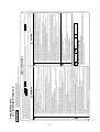
SAFETY PRECAUTIONS
This instruction manual illustrates the method of installing an indoor unit.
For electrical wiring work, please see instructions set out on the backside.
For outdoor unit installation and refrigerant piping, please refer to the installation manual that comes with your outdoor unit.
A wired remote control unit is supplied separately as an optional part.
z Execute proper grounding. Do not connect the ground wire to a gas pipe, water pipe, lightning rod or a telephone ground wire. Improper placement of
ground wires can result in electric shock.
z Do not put the drain pipe directly into the ditch where toxic gas such as sulfur is generated.
Toxic gas would flow into the room. Also, this may cause corrosion of indoor unit, and malfunction or refrigerant leakage.
z Be sure to bring back the packing material, form polystyrene, band and vinyl back etc., of the indoor and/or outdoor units after complete the installation
work, and then implement appropriate measures such as breaking them.
z When setting up or moving the location of the air conditioner, do not mix air etc. or anything other than the designated refrigerant (R410A) within the
refrigeration cycle.
Rupture and injury caused by abnormal high pressure can result from such mixing.
z Do not processing, splice the power cord, or share a socket with other power plugs.
This may cause fire or electric shock due to defecting contact, defecting insulation and over-current etc.
z Do not bundling, winding or processing for the power cord. Or, do not deforming the power plug due to tread it
This may cause fire or heating.
z Do not vent R410A into the atomosphere:R410A is a fluor inated greenhouse gas. covered by the Kyoto Protocol with a Groval Warming Potential (GWP)
=1975
z To disconnect the appliance from the mains supply this appliance must be connected to the mains by means of a circuit breaker or a switch (use a
recognized 16A) with a contact separation of at least 3mm.
z The appliance shall be installed in accordance with national wiring regulations.
z When a plug is connected to the power cord, a plug conforming to the IEC60884-1 standard must be used.
z This system should be applied to places as households, residences and the like. Application to inferior environment such as engineering shop could
cause equipment malfunction.
z Please entrust installation to either the company which sold you the equipment or to a professional contractor. Defects from improper installations can be
the cause of water leakage, electric shocks and fires.
z Execute the installation accurately, based on following the installation manual. Again, improper installations can result in water leakage, electric shocks
and fires.
z For installation, confirm that the installation site can sufficiently support heavy weight. When strength is insufficient, injury can result from a falling of the
unit.
z For electrical work, please see that a licensed electrician executes the work while following the safety standards related to electrical equipment, and local
regulations as well as the installation instructions, and that only exclusive use circuits are used.
Insufficient power source circuit capacity and defective installment execution can be the cause of electric shocks and fires.
z Accurately connect wiring using the proper cable, and insure that the external force of the cable is not conducted to the terminal connection part, through
properly securing it. Improper connection or securing can result in heat generation or fire.
z Take care that wiring does not rise upward, and accurately install the lid/service panel. It's improper installation can also result in heat generation or fire.
z Always use accessory parts and authorized parts for installation construction. Using parts not authorized by this company can result in water leakage,
electric shock, fire and refrigerant leakage.
z Ventilate the work area when refrigerant leaks during the operation.
Coming in contact with fire, refrigerant could generate toxic gas.
z Confirm after the foundation construction work that refrigerant does not leak.
If coming in contact with fire of a fan heater, a stove or a movable cooking stove, etc., refrigerant leaking in the room could generate toxic gas.
z Turn off the power source during working on the inside of the unit such as servicing or installing work.
This may cause electric shock.
z Use only pipe, flare nut and tools that have been designed to operate with R410A.
Using existing parts (R22) may cause the unit failure, even as due to serious accident such as explosion of the cooling cycle or injury etc.
z For pump down work, stop the compressor before removing the refrigerant pipe.
If the refrigerant pipe is removed when the compressor is in operation with the service valves open (liquid side and gas side), air would be mixed in the
refrigerant circuit and this may cause explosion and injuries due to abnormal high pressure in the cooling cycle.
z Connect the pipes for refrigerant circuit securely in installation work before compressor is operated
If the compressor is operated when the service valve is open without connecting the pipe, this may cause frostbite and injuries due to refrigerant leakage
rapidly. Also, the unit is absorbed the air etc., this may cause explosion and injuries due to abnormal high pressure in the cooling cycle.
z Tighten the flare nut by torque wrench with specified method.
If the flare nut were tightened with excess torque, this may cause burst and refrigerant leakage after a long period, and then, this may cause generate the
harmful substance due to touch the flammable materials.
z Make sure there is no dust or clogging on both plug and socket nor loose connection of the socket before plugging of the power plug. Then, the power
plug must be inserted tightly.
Accumulation of dust, clogging on the socket or plug, or loose installation of the socket may cause electric shock and fire. Replace the socket if it is loose.
z Do not open the service valves (liquid side and gas side) until refrigerant piping construction, air-tightness test and evacuation are completed
This may cause frostbite and injuries due to refrigerant leakage rapidly. Also, if the refrigerant gas leakage occurs during installing work, stop the work
such as brazing work and then ventilation of the room. This may cause generate the toxic gas due to touch the flammable materials.
WARNING
Observe instructions with
great care
Provide proper earthing
c The system should be applied to places as households, residences and the like.
c The equipment shall be installed in accordance with national wiring regulations.
c The connection to the fixed wiring of the mains supply must be made via a double pole isolating switch with a contact gap of at least 3mm in each pole.
c When the outdoor unit has a possibility of being overturned or being displaced and fall from its original installation position, the outdoor unit should be
fixed in its position by use of anchor bolts or wires.
CAUTIONS FOR INSTALLATION
Strictly prohibited
z Symbols which appear frequently in the text have the following meaning
z Do not install the unit where there is a concern about leakage of combustible gas.
The rare event of leaked gas collecting around the unit could result in an outbreak of fire.
z Do not touch the suction or aluminum fin on the outdoor unit
This may cause injury.
z Do not install the outdoor unit where is likely to be a nest for small animals
Small animals may come into the electronic components and may cause breakdown and fire. Also,instruct the user to keep the surroundings clean.
z Do not install the outdoor unit at the place where fan airflow falls on the garden tree etc.
This may cause damage to the garden tree etc., due to the fan airflow.
z Do not put anything on the outdoor unit and operating the unit.
This may cause damage the objects or injury due to falling to the object.
z Please avoid installing this unit in the locations where oil splashes and moisture are abundant (e.g., kitchens, mechanical workshops) or where the outside
air is likely to flow in. These locations may cause corrosion and lower performance of the heat exchanger and cause damage to plastic parts.
z Please avoid installing this unit in the locations with corrosive gases (such as sulfurous acid gas), inflammable gases (such as thinner, gasoline) and areas
where there are possibilities of gas accumulation or where a volatile inflammable material is handled. These locations can cause corrosion to the heat
exchanger and damage to plastic parts. Also, the inflammable gas could cause fire.
z Please avoid installing this unit in the vicinity of equipment generating electromagnetic waves such as hospital equipment or equipment generating
high-frequency waves. A failure to observe this instruction may result in controller performance errors due to noise generation.
z Please avoid installing and using this unit in a place where it is subject to sea breezes (coastal area). Installation in such a place may result in the corrosion
of exterior panels and the heat exchanger.
z Do not place the remote control at locations that receives direct sunlight. This may cause malfunction and deformation.
z Spatters from welding, etc., if hit the unit, can damage (pinhole) its drain pan and other components and cause a water leak. Care must be taken in
performing a welding operation near this unit and take necessary precautions to prevent spatters from entering this unit.
z For installation work, be careful not to get injured with the heat exchanger, piping flare portion or screws etc.
z For the drain pipe, follow the installation manual to insure that it allows proper drainage and thermally insulate it to prevent condensation. Inadequate
plumbing can result in water leakage and water damage to interior items.
z The installation of an earth leakage breaker is necessary depending on the established location of the unit. Not installing an earth leakage breaker may
result in electric shock.
z When perform the air conditioner operation (cooling or drying operation) in which ventilator is installed in the room. In this case, using the air conditioner in
parallel with the ventilator, there is the possibility that drain water may backflow in accordance with the room lapse into the negative pressure status.
Therefore, set up the opening port such as incorporate the air into the room that may appropriate to ventilation (For example; Open the door a little). In
addition, just as above, so set up the opening port if the room lapse into negative pressure status due to register of the wind for the high rise apartment etc.
z Secure the regulated space for inspection and maintenance
When it is not possible to keep enough space, this may cause injury due to falling from the installation place.
z To prevent the falling, institute the everlasting ladder and handrail etc., to the aisle when installing the outdoor unit in the location with rooftop or altitude.
Or, for surrounding of the outdoor unit, institute the fence and handrail etc., to the aisle to prevent the falling.
z Performing the heat insulation and condensation of the refrigerant piping
If the heat insulation and condensation of the refrigerant piping is not correctly, this may cause the water leakage, dew dropping and household wetting etc.
z Be careful not to injury due to damage of the unit installing work when leaving of the packaging materials.
CAUTION
z Please read these "Safety Precautions" first then accurately execute the installation work.
z For installing qualified personnel, take precautions in respect to themselves by using suitable protective clothing, groves, etc., and then perform the installation works.
z Though the precautionary points indicated herein are divided under two headings,
WARNING section. However, there is also a possibility of
CAUTION , those points which are related to the strong possibility of an installation done in error resulting in death, serious injury or environmental pollution are listed in the
WARNING and
serious consequences in relationship to the points listed in the
CAUTION section as well. In either case, important safety related information is indicated, so by all means, properly observe all that is mentioned.
z Please pay attention not to fall down the tools, etc. when installing the unit at the high position.
z After completing the installation, along with confirming that no abnormalities were seen from the operation tests. Please explain operating methods as well as maintenance methods to the user (customer) of this equipment, based on the user's manual. Moreover, ask the customer to keep this sheet together with the user's manual.
z If unusual noise can be heard during operation, consult the dealer.
RKY012A007
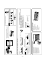
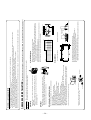
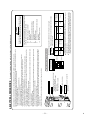
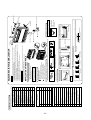
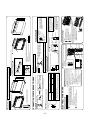
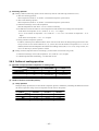
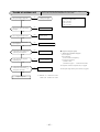
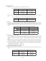
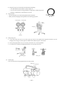
1.5 Application data
1.5.1 Installation of indoor unit
1
4
2
Remote control holder
Tapping screws
(for installation board 4dia. by 25mm)
③
④
2
1
Filter holders
(Attached to the front panel of indoor unit)
Insulation (#486 50 x 100 t3)
⑦
⑧
⑨
1
Piping cover
(for insulation of connection piping)
Hammer
Spanner wrench
Torque wrench
Hole core drill (65mm in diameter)
Wrench key (Hexagon) [4m/m]
5
6
7
8
9
13
12
11
10
Tape measure
4
Pipe bender
(
Gauge for projection adjustment
Used when flare is made by using
conventional flare tool
Flaring tool set
)
specifically
( Designed
)
for R410A
Designed specifically
Gas leak detector (
)
for R410A
)
Saw
3
(
Knife
2
14.0 ~ 61.0N•m
(1.4 ~ 6.1kgf•m)
Plus headed driver
1
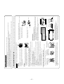
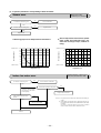
Necessary tools for the installation work
1
Drain hose (extention hose)
1
Inclination plate
1
1
Putty
1
Sleeve
Q'ty
Sealing plate
Option parts
2
Air-cleaning filters
⑥
2
Wood screw
(for remote control switch holder 3.5(mm). by 16mm)
Battery [R03(AAA,Micro) 1.5V]
⑤
1
Wireless remote control
②
1
Q'ty
Installation board
(Attached to the rear of the indoor unit)
①
Standard accessories (Installation kit)
Accessories for indoor unit
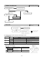
c Before installation check that the power supply matches the air conditioner.
Mounting
board
Max.10
Nut
(M6)
the standard hole as the center.
cAdjust so the board will be level by turning the board with
Standard hole
direction is to be conducted with four screws in a temporary
tightened state.
cAdjustment of the installation board in the horizontal
5 cm
m
from inimum
the w
all
65
5
Outdoor side
b Top
c Hold the bottom of the
piping and fix direction
before stretching it and
shaping it.
Drain hose
Pipings
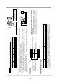
c Tape only the portion
that goes through the
wall.
c Always tape the wiring
with the piping.
Taping of the exterior
In case of piping in the right rear direction
Shaping of pipings
Thicknese of the wall + 1.5cm
Indoor side
b
Turn to
tighten
Outdoor side
a
c
Installed state
c Remove the screw and
drain hose, making it
rotate.
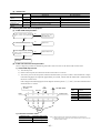
Right-hand-side piping
35
54
Space for
service 100
120
220
Downward Left rear
Left
Left downward
Rear
Right
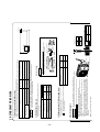
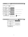
Piping is possible in the rear, left,
left rear, left downward, right or
downward direction.
Piping hole (ø65)
Piping for Gas 491.1
Piping for Liquid 559.1
Drain hose (ø16) 520.8
35
Indoor unit
Installation board
650
450
Piping hole (ø65)
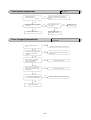
4. Connect the drain hose.
Piping in the right direction
58
220
Space for
service
Piping for Liquid (20 to 60 type) : ø6.35
Piping for Gas (20 to 35 type) : ø9.52
(50 to 60 type) : ø12.7
Piping in the right rear direction
3. Insert the drain cap.
50
120
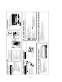
INSTALLATION SPACE (INDOOR UNIT)(FRONT VIEW)
Relation between setting plate and indoor unit
Wood screws
Remote control holder
Wireless remote control
Sleeve
(sold separately)
Installation board
1 0 cm
m
from inimum
the w
all
6.5 cm minimum from the ceiling
c Remove it with hand or c Insert the drain cap which was removed c Insert the drain hose securely,
pilers.
at procedure “2” securely using a
making rotate. And install the
hexagonal wrench etc.
screw.
Note: Be careful that If it is not Inserted
Note: Be careful that If it is not
securely, water leakage may
Inserted securely, water
occur.
leakage may occur.
1. Remove the drain hose. 2. Remove the drain cap.
[Drain hose changing procedures]
Piping in the left direction
Piping in the left rear direction
Left-hand-side piping
z Matters of special notice when piping from left or central/rear of tha unit.
[Top view]
c In case of rear piping draw out, cut off the lower
and the right side portions of the sleeve collar.
Installing the support of piping
c Drill a hole with whole core drill.
Indoor side
When drilling the wall that contains a metal lath, wire lath or metal plate, be sure to use pipe hole sleeve sold separately.
Drilling of holes and fixture of sleeve (Option parts)
Mounting
board
Bolt
(M6 12)
Fixing on concrete wall
Use of nut anchor
Use of bolt anchor
Mating mark for
level surface
Level position (2 locations)
450
Look for the inside wall structures (Intersediats support or pillar and finally
install the unit after level surface has been checked.)
Installation of Installation board
INSTALLATION OF INDOOR UNIT
c A place where the air conditioner can be received the signal surely during operating the wireless remote control.
c Places where there is no affected by the TV and radio etc.
c Do not place where exposed to direct sunlight or near heat devices such as a stove.
Wireless remote control
c Where there is no obstructions to the air flow and where the cooled and heated air can be evenly distributed.
c A solid place where the unit or the wall will not vibrate.
c A place where there will be enough space for servicing. (Where space mentioned below can be secured)
c Where wiring and the piping work will be easy to conduct.
c The place where receiving part is not exposed to the direct rays of the sun or the strong rays of the street lighting.
c A place where it can be easily drained.
c A place separated at least 1m away from the television or the radio. (To prevent interference to images and sounds.)
c Places where this unit is not affected by the high frequency equipment or electric equipment.
c Avoid installing this unit in place where there is much oil mist.
c Places where there is no electric equipment or household under the installing unit.
Indoor unit
(Install at location that meets the following conditions, after getting approval from the customer)
49
222.5
48
SELECTION OF INSTALLATION LOCATION
65 Space for service
BEFORE INSTALLATION
7.7
48
295.7
5.6
15 -
15 Space for service
-
-
16 -
Wall
Indoor unit
Installation
borad
Latch
(2 locations)
Installation Steps
2 Gently push the lower
part to secure the unit.
1 Pass the pipe through
the hole in the wall,
and hook the upper
part of the indoor unit
to the installation board.
Press
Remove
(Do not turn)
Liquid side
Gas side
Position it so that the slit area faces upward.
Use an attached insulation pad for heat insulation.
Clamp
Wood screw
Drain hose
Outer tape
Connection wiring,
Earth wiring
Refrigerant piping
Finishing work and fixing
c Fitting
① Do remove the air filter.
② Cover the body with the front panel.
③ Fit the 4 latches in the upper section.
④ Tighten the 5 set screws.
⑤ Fit the air filter.
⑥ Fit the air input panel.
How to remove and fit the front panel
Copper pipe
0.0 - 0.5
0.0 - 0.5
0.0 - 0.5
Clutch type flare tool for
R410A
c Removing
① Remove the air inlet panel.
② Remove the 5 set screws.
③ Remove the 4 latches in the upper section.
④ Move the lower part of the panel forward and
push upwards to remove.
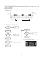
Flaring
block
Wavy
The gap to the ground is
5 cm or less.
The drain hose
tip is in the gutter.
1.0 - 1.5
1.0 - 1.5
2.0 - 2.5
1.5 - 2.0
Conventional (R22) flare tool
Clutch type
Wing nut type
1.0 - 1.5
1.5 - 2.0
Set screws
Cover the exterior portion with outer tape and
shape the piping so it will match the contours
of the route that the piping to take.
Also fix the wiring and pipings to the wall with
clamps.
latch
Do not apply excess torque to the flared nuts.
Otherwise, the flared nuts may checkdepending.
CAUTION
When it is exposed indoor. Extended drain hose
Measurement B (mm)
Drain hose
Use a flare tool designed for R410A or a conventional flare tool.
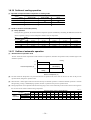
Please note that measurement B (protrusion from the flaring block) will vary depending on the
type of a flare tool in use.
If a coventional flare tool is used, please use a copper pipe gauge or a similar instrument to
check protrusion so that you can keep measurement B to a correct value.
ø12.7
ø9.52
ø6.35
Copper pipe diameter
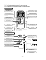
Open/close and detachment/attachment of the air inlet panel
z Cover the indoor unit’s flare-connected joints, after they are checked for a gas leak, with an indoor
unit heat insulating material and then wrap them with a tape with an attached insulation pad placed
over the heat insulating material’s slit area.
Vinyl tape
Cover the coupling with insulator and then cover it with tapes.
Insulation of the connection portion
then flared the pipes.
Do not apply refrigerating machine
oil to the flared surface.
Measurement B
z Flaring work
The drain hose
tip is in water.
Odor from
the gutter
drainage is all right. Otherwise water leak may occur.
Wall
CAUTION Go through all installation steps and check if the
Pipe accommodating section
Gutter
c Pour water to the drain pan located under the heat exchanger, and ensure that the water is discharged outdoor.
c When the extended drain hose is indoor, always use a shield pipe (to be arranged by the user) and ensure it is
thermally insulated
Shield pipe
Higher than specified
c Arrange the drain hose in a downward angle
c Avoid the following drain piping.
Drainage
Since this air conditioner has been designed to collect dew drops on the rear
surface to the drain pan, do not attach the power cord above the gutter.
c To open, pull the panel at both ends of lower part
and release latches, then pull up the panel until
you feel resistance.
(The panel stops at approx. 60 open position)
c To close, hold the panel at both ends of lower
part to lower downward and push it slightly until
the latch works.
c To remove, pull up the panel to the position
shown in right illustration and pull it toward you.
c To install, insert the panel arm into the slot on the
front panel from the position shown in right
illustration, hold the panel at both ends of lower
part, lower it downward slowly, then push it
slightly until the latch warks.
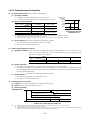
Liquid side (ø6.35) : 14.0 - 18.0 N·m (1.4 - 1.8 kgf·m)
Gas side (ø9.52) : 34.0 - 42.0 N·m (3.4 - 4.2 kgf·m)
(ø12.7) : 49.0 - 61.0 N·m (4.9 - 6.1 kgf·m)
c Connect the pipes on both liquid and gas sides.
c Tighten the nuts to the following torque.
Indoor
Connection
Dimension A
Liquid side ø6.35 : 9.1 (mm)
Gas side ø9.52 : 13.2 (mm)
ø12.7 : 16.6 (mm)
c Install the removed flared nuts to the pipes to be connected,
A
CAUTION
Keep the openings of the pipes covered with tapes etc. to prevent dust, sand, etc. from entering them.
c Remove the flared nuts. (on both liquid and gas sides)
(Do not turn)
Indoor
Preparation
The marked portion of the indoor
unit base lower latch.
① Push up at the marked portion of the indoor unit base lower latch, and slightly pull it
toward you. (both right and left hand sides) (The indoor unit base lower latch can be
removed from the installation board)
② Push up the indoor unit upward. So the indoor unit will be removed from the installation
board.
z How to remove the indoor unit from the installation board
CONNECTION OF REFRIGERANT PIPINGS
Indoor unit base lower latch
Installation borad
Fixing of indoor unit
90 ± 0.5°
-
17 -
CAUTION
RNR4G1.5 (example) or 245IEC57
Harmonized cable type
300/500 volts
Natural-and/or synth, rubber wire insulation
Polychloroprene rubber conductors insulation
Stranded core
Number of conductors
One conductor of the cable is the earth conductor
(yellow/green)
1.5 Section of copper wire (mm2)
H05
H
05
R
N
R
4or5
G
Use cables for interconnection wiring to avoid loosening of the
wires.
CENELEC code for cables Required field cables.
In case of faulty wiring connection, the indoor unit stops, and
then the run lamp turns on and the timer lamp blinks.
⑥ Battery
Cover
⑤ Wood screw
3.5 16
② Wireless remote control
䂾Conventionally, operate the remote control switch by holding in your hand.
䂾Avoid installing it on a clay wall etc.
Fixing to pillar or wall
Gas side : Fully open the gas valve
Carry out cooling operation . (If indoor temperature is low, operate
forced cooling operation.)
③ After low pressure gauge become 0.01MPa, stop cooling operation
and close the gas valve.
<How to pump down>
① Connect charge hose to service port of outdoor unit.
② Liquid side : Close the liquid valve with hexagon wrench key.
outdoor unit when the pipes are removed from the unit.
c In order to protect the environment, be sure to pump down (recovery of refrigerant).
c Pump down is the method of recovering refrigerant from the indoor unit to the
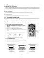
Unit ON/OFF button
Forced cooling operation
Turn on a power supply again after a while after turn off a power supply.
Then press continually the ON/OFF button 5 seconds or more.
HOW TO RELOCATE OR DISPOSE OF THE UNIT
Do not use new and
old batteries together.
CAUTION
Mounting method of battery
INSTALLATION OF REMOTE CONTROL SWITCH
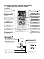
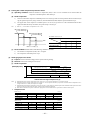
①
②
③
④
Open the air inlet panel.
Remove the service panel.
Remove the wiring clamp
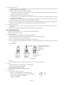
Connect the connecting wire securely to the terminal block.
1 ) Connect the connection wire securely to the terminal
block. If the wire is not affixed completely, contact will be
poor, and it is dangerous as the terminal block may heat
up and catch fire.
2 ) Take care not to confuse the terminal numbers for indoor
and outdoor connections.
3 ) Fix the connection wire using the wiring clamp.
⑤ Fix the connecting wire by wiring clamp.
⑥ Attach the service panel.
⑦ Close the air inlet panel.
Mounting of connecting wires
Preparation of indoor unit
ELECTRICAL WIRING WORK
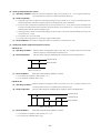
Air-cleaning filter
Filter holder
1. Open the air inlet panel and remove the air filters.
2. Install the filter holders, with the air-cleaning filters installed in the holders.
In the air conditioner.
• Each air-cleaning filter can be installed in the left or right filter holder.
3. Install the air filters and close the inlet panel.
Operation of the unit has been explained to the customer.
(Three-minutes restart preventive timer)
When the air conditioner is restarted or when changing the operation, the unit
will not start operating for approximately 3 minutes.
This is to protect the unit and it is not a malfunction.
In connecting an interface, connect to the respective terminal securely with the connection harness supplied
with an optional “Interface connection kit SC-BIKN-E” and fasten the connection harness onto the indoor control
box with the clamp supplied with the kit.
For more details, please refer to the user's manual of your “Interface connection kit SC-BIKN-E”.
① Remove the front panel and lid of control.
② There is a terminal (respectively marked with CNS) for the indoor control board.
CONCERNING TERMINAL CONNECTION FOR AN INTERFACE
Air conditioning operation is normal.
No abnormal noise.
Water drains smoothly.
Protective functions are not working.
The remote control is normal.
Test run
The power supply voltage is correct as the rating.
No gas leaks from the joints of the operational valve.
Power cables and crossover wires are securely fixed to the terminal board.
Operational valve is fully open.
The pipe joints for indoor and outdoor pipes have been insulated.
After installation
Check the following points again after completion of the installation, and before turning on the power. Conduct a test run again and ensure that the unit operates properly.
At the same time, explain to the customer how to use the unit and how to take care of the unit following the user's manual.
INSTALLATION TEST CHECK POINTS
Clamp
Terminal block
Service panel
Installing the air-cleaning filters
- 18 -
㧖
1
Drain elbow (Heat pump type only)
ԙ
1
1
1
1
1
1
Sleeve
Inclination plate
Putty
Drain hose (extention hose)
Piping cover
(for insulation of connection piping)
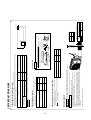
PRECAUTIONS FOR SAFETY
Always do it according to the instruction.
٨ Beware of danger from a dropped tool or the like in installing the unit in an elevated position.
٨ When the air conditioning unit makes abnormal sounds in operation, consult with your dealer.
Never do it under any circumstances.
installation,along with confirming that no abnormalities were seen from the operation test. Explain operating methods as well as maintenance
methods to the user of this equipment, based on the owner’s manual.
٨ Ask the customer to keep this manual together with the operation manual.
٨ In installing the unit, you must also take thorough safety precautions to protect your person.
A failure to observe any safety instruction listed under “
Caution” can also result in a serious consequence depending on the circumstances.
Please observe all these instructions, because they include important points concerning safety.
٨ The meanings of “Marks” used here are as follows:
WARNING : Improper installation could result in serious accident causing death, serious injury or environmental pollution.
CAUTION : Improper installation could result in serious accident.
installing the equipment, carefully read the Precautions for safety and make sure that safety is maintained.
safety items contain important information regarding safety. Be sure to follow them. The symbols used and their meanings are as follows.
٨ After
٨ The
٨ When
Q’ty
Sealing plate
Option parts
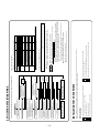
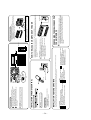
٧This installation manual deals with outdoor units and general installation specifications only. For indoor units, refer to the respective
installation manuals supplied with the units.
٧Read this manual carefully before you set to installation work and carry it out according to the instructions contained in this manual.
1
Gromet (Heat pump type only)
Accessories for outdoor unit
Ԙ
٨
٨
Model name and power source
Refrigerant piping length
٨ Piping, wiring and miscellaneous small parts
٨ Indoor unit installation manual
Check before installation work
Models SRC20ZIX-S, 25ZIX-S, 35ZIX-S
1.5.2 Installation of outdoor unit
Charge hose (Designed specifically for R410A)
Flaring tool set (Designed specifically for R410A)
Gas leak detector (Designed specifically for R410A)
Gauge for projection adjustment
(Used when flare is made by using conventional flare tool)
13
14
15
16
Vacuum pump
10
Gauge manifold (Designed specifically for R410A)
Wrench key (Hexagon) [ 4 m/m]
9
12
Hole core drill (65mm in diameter)
8
Vacuum pump adapter
(Designed specifically for R410A)
(Anti-reverse flow type)
Torque wrench (14.0㨪 62.0Nm (1.4 㨪 6.2kgfm))
7
11
Spanner wrench
Hammer
Tape measure
Saw
Knife
Plus headed driver
6
5
4
3
2
1
Necessary tools for the installation work
Model 202535
Designed for R410A refrigerant
RWC012A030 a
-
19 -
installation work must be performed according to the installation manual as dedicated circuits exclusively for the air conditioning system in
compliance with the applicable “Technical standards for electrical installation”and “Indoor wiring regulations.”
r service panel securely.
an air purge are completed.
.
Do not connect the grounding wire to a gas pipe, water pipe, lightning rod, or telephone ground wire.
If a defect is in a ground, it will become a cause of an electric shock at the time of failure or a short circuit.
●E
nsure that the unit is properly grounded.
A failure to observe this instruction can result in heat generation or ignition.
●N
ever bundle, wind or modify the power cord. Do not step onto the power plug or otherwise deform it.
A failure to observe this instruction can result in a fire or electric shock from improper contact, improper insulation, excessive current beyond rating, etc.
●N
ever modify the power cord, introduce an intermediate connection or connect it in a daisy chain
If air or other foreign matters gets into the refrigerant cycle, an abnormal pressure build-up will occur, which can result in pipe rupture or injury.
must collect, bring back and shred or otherwise properly dispose of all packaging materials, expanded polystyrene, bands, vinyl bags and so on used for
the transpiration of the indoor and outdoor units after installation work.
● In installing or transferring an air conditioning system, never allow air or other foreign matters than specified refrigerant (R410A) to get into the refrigerant cycle (piping).
● You
This will pose a risk of a toxic gas flowing back into the room. This can also cause the corrosion of the indoor unit and a resultant unit failure or refrigerant leak.
● Do not run the drain piping directly into the sewer where a toxic gas such as sulfuric gas is generated.
A failure to observe this instruction can result in frost bite or injury from an abrupt refrigerant outflow. If refrigerant gas leaks during installation work, immediately stop pipe
blazing and other work and ventilate the room.
●N
ever open the operation valves (either liquid or gas side) until refrigerant pipe installation work, an air-tightness test and
Dust deposits, clogging or wobble can result in an electric shock or fire. If the outlet is loose, change it with a new one.
inserting the power cable plug, make sure that no anomalies such as dust deposits, socket clogging or wobble are found in both the plug and outlet and
insert the plug fully to the roots of its blades.
● In
Over-tightening a flare nut can cause a refrigerant gas leak from breakage after years of operation and the generation of a toxic product, if refrigerant gas comes into contact with bare fire.
● Tighten a flare nut with a torque wrench in a specified manner.
If you run the compressor without attaching the refrigerant pipe and with the operation valves (liquid and gas sides) open, you may incur frost bite or injury from an abrupt
refrigerant outflow. An abnormal pressure build-up may also occur in the refrigeration cycle as a result of the inhalation of air, which can result in pipe rupture or injury.
● In installing the unit, be sure to attach the refrigerant pipe before operating the compressor.
If you detach the pipe with the compressor running and the operation valves (liquid and gas sides) open, an abnormal pressure build-up will occur in the refrigeration cycle, which
can result in pipe rupture or injury.
● In carrying out a pump-down process, stop the compressor before you detach the refrigerant pipe.
The diversion of existing materials (designed for R22) can result in a unit failure as well as a serious accident such as refri geration cycle rupture or injury.
●U
se pipes, flare nuts and tools specifically designed for R410A.
Refrigerant gas, if it comes into contact with bare fire, can cause the generation of a toxic gas.
● If refrigerant gas leaks during installation work, ventilate the room.
A failure to use genuine parts approved by the manufacturer may result in a fall of the unit, a water leak, a fire, an electric shock, a refrigerant leak, substandard performance or a control failure.
●U
se only parts supplied with the unit and approved supply parts for installation work.
Improper installation can cause heat generation at terminal connections and a resultant fire or electric shock.
●N
eatly arrange the cables connecting between indoor and outdoor units so that they may not get loose, and put on the lid and/o
A defect in power supply circuits such as insufficient capacity or improper installation can cause an electrical shock or fire.
● Always connect between indoor and outdoor units securely with specified cables. N
ever use an intermediate connection or stran ded wire for this purpose.
Fasten cables securely so that the terminal block may not be subject to external force working through cables.
Improper connection or fastening can cause heat generation and a resultant fire.
●E
lectrical
Insufficient strength or improper installation can cause a fall of the unit and resultant injury.
● Install the unit securely onto a structure that is strong enough to sustain its weight.
A failure to observe this instruction can result in an electric shock.
● Always turn off power before you work inside the unit such as for installation or servicing.
Improper installation work can result in a water leak, electric shock, or fire.
●C
arry out installation work properly according to this installation manual.
Improper installation work performed on the part of a user can result in a water leak, electric shock or fire.
disconnect the appliance from the mains supply this appliance must be connected to the mains by means of a circuit breaker or a switch
(use a recognized 16A) with a contact separation of at least m
3 m.
● The appliance shall be installed in accordance with national wiring regulations.
● This system should be applied to places as households, residences and the like. Application to inferior environment such as engineering shop
could cause equipment malfunction.
● Ask your dealer or a specialized service provider to install the unit.
● To
WARNING
CAUTION
A failure to observe this instruction can result in a fall of the article and resultant property
damage or personal injury.
● Do not operate the outdoor unit with any article placed on it.
Fan winds can affect adversely to the plant etc.
● Do not install the outdoor unit where its fan winds directly hit a plant etc.
If they enter the unit and touch electrical parts inside, they may cause a unit failure or fire.
Please ask the customer to keep the surroundings clean.
● Do not install the outdoor unit in a place where small animals are likely to inhabit.
You may incur injury if you touch them.
● Do not touch the air intake and aluminum fins of the outdoor unit.
Should gas leak and gather around the unit, it can cause the ignition of gas.
● Do not install the unit in the place where a risk of inflammable gas leaks exists.
contents or incur injury from such work.
● In removing packaging materials, take sufficient care so as not to damage the
Improper heat insulation given to refrigerant piping for condensation prevention can result in
leaking or dripping water soaking household effects.
provide permanent ladders and handrails along the access path and fences or
handrails surrounding the outdoor unit.
● Dress the refrigerant piping with a heat insulation material to prevent condensation.
● When the outdoor unit is installed on a roof top or in an elevated position,
An insufficient service space can result in a fall from the installation point and resultant injury.
fan and it is used (for a cooling or dehumidifying operation) simultaneously
with the ventilating fan, the room may have a negative air pressure relative to the
exterior, which can cause a reverse flow of drain water. Make sure that the room
has an opening that allows the inflow of as much air as discharged by the
ventilation fan. (For example, open the door a little) Similarly, provide an adequate
opening, if a room has a negative air pressure relative to the exterior due to the effect
of winds in a high-rise condominium building or the like.
● Secure a service space for inspection and maintenance as specified in the manual.
● When the air conditioning system is installed in a room equipped with a ventilating
A failure to install an earth leakage breaker can cause an electric shock.
leakage breaker is essential.
● When the unit is installed in a humid or damp place, the installation of an earth
Improper installation can result in a flood of water in the room and soaked household effects.
and give it heat insulation to prevent condensation.
● Install drain piping according to the installation manual to ensure good drainage,
pipe flares and screws during work.
● Take sufficient care so that you may not incur injury from heat exchanger fins,
Heavy
Wind direction
2.Install so the direction of the air from the blowing outlet will be
perpendicular to the direction of the wind.
Over 500mm
1.Place the unit outlet pipe perpendicular to the wind direction.
Wind direction
Be careful of the following conditions and choose an installation place.
〇 Where air is not trapped.
〇 Where the installation fittings can be firmly installed.
〇 Where wind does not hinder the intake and outlet pipes.
〇 Out of the heat range of other heat sources.
〇 A place where stringent regulation of electric noises is applicable.
〇 Where it is safe for the drain water to be discharged.
〇 Where noise and hot air will not bother neighboring residents.
〇 Where snow will not accumulate.
〇 Where strong winds will not blow against the outlet pipe.
〇 A place where no TV set or radio receiver is placed within 5m.
(If electrical interference is caused, seek a place less likely to cause the problem)
〇 If a operation is conducted when the outdoor air temperature is -5℃ lower, the outdoor unit should be installed
at a place where it is not influenced by natural wind.
〇 Where it is likely that the unit is subjected to strong winds, provide wind guards according to the following guidelines.
Strong winds can cause performance degradation, an accidental stop due to a rise of high pressure and a broken fan.
3) Selecting the installation location
right hand side of the unit as viewed from the front (diffuser side) is heavier.
A person carrying the right hand side must take heed of this fact. A person carrying
the left hand side must hold with his right hand the handle provided on the front panel
of the unit and with his left hand the corner column section.
● The
2) Portage
Pad
L1
L2
L3
L4
Example installation
Outlet
Intake
510
Ⅱ
280
75
80
Open
Ⅲ
280
Open
80
250
Model 20, 25, 35
157.8
Ⅰ
Open
100
100
250
Intake
L2
Outlet
Intake
Use a long block to
extend the width.
L3
L1
L4
service
( space )
Improper installation can result in a compressor failure, broken piping within the unit and abnormal noise generation.
winds, etc.
Use a thicker block to anchor deeper.
Fasten with bolts
(M10-12)
② Notabilia for installation
Ⅳ
180
Open
80
Open
The height of a wall is 1200mm or less.
● In installing the unit, fix the unit’s legs with bolts specified on the left.
● The protrusion of an anchor bolt on the front side must be kept within 15 mm.
● Securely install the unit so that it does not fall over during earthquakes or strong
● Refer to the above illustrations for information regarding concrete foundations.
● Install the unit in a level area. (With a gradient of 5 mm or less.)
111
① Anchor bolt fixed position
5) Installation
Size
(mm)
or wider interval between them as a
service space. In order to facilitate servicing of controllers, please provide a sufficient space between units
so that their top plates can be removed easily.
● Where a danger of short-circuiting exists, install guide louvers.
● When more than one unit are installed, provide sufficient intake space consciously so that short-circuiting may not occur.
● Where piling snow can bury the outdoor unit, provide proper snow guards.
● Walls surrounding the unit in the four sides are not acceptable.
● There must be a 1-meter or larger space in the above.
● When more than one unit are installed side by side, provide a 250mm
4) Installation space
When a unit is hoisted with slings for haulage, take into consideration the offset of its gravity center position.
If not properly balanced, the unit can be thrown off-balance and fall.
(Take particular care in carrying in or moving the unit, and always perform such an operation with two or more persons.)
the unit as close as possible to the installation site before removing it from
the packaging.
● When you have to unpack the unit for a compelling reason before you haul it to the
installation point, hoist the unit with nylon slings or ropes and protection pads so that
you may not damage the unit.
● Deliver
1) Delivery
CAUTION
1. HAULAGE AND INSTALLATION
not use any refrigerant other than R410A. R410A will rise to pressure about 1.6 times higher than that of a conventional refrigerant.
A cylinder containing R410A has a pink indication mark on the top.
● A unit designed for R410A has adopted a different size indoor unit operation valve charge port and a different size check joint provided in the unit to prevent the charging of a wrong refrigerant by mistake.
The processed dimension of the flared part of a refrigerant pipe and a flare nut's parallel side measurement have also been altered to raise strength against pressure.
Accordingly, you are required to arrange dedicated R410A tools listed in the table on the right before installing or servicing this unit.
● Do not use a charge cylinder. The use of a charge cylinder will cause the refrigerant composition to change, which results in performance degradation.
● In charging refrigerant, always take it out from a cylinder in the liquid phase.
● All indoor units must be models designed exclusively for R410A. Check connectable indoor unit models in a catalog, etc. (A wrong indoor unit, if connected into the system, will impair proper system operation)
Notabilia as a unit designed for R410A
● Do
288.8
24.3
312.5
351.6
20 14.8
-
21 -
10m or less
Refrigerant piping (branch pipeL)
Ǿ6.35
Ǿ6.35
Ǿ6.35
Flare
●Tighten a flare joint securely with a double spanner.
Side cover
Screw
Nitrogen
gas
A
Copper
In the case of a rigid (clutch) type
pipe outer
diameter With an R410A tool With a conventional tool
φ6.35
0∼0.5
1.0∼1.5
φ9
.52
(mm)
L
Indoor unit
Copper pipe protrusion for flaring : B
Flared pipe end : A (mm)
Copper
pipe outer A 0
ー0.
4
diameter
φ6.35
9.
1
φ9
.52
13.2
Hand
0.5MPa
Secondary side
Relief valve
Primary side
Station valve
*Phosphorus deoxidized seamless copper pipe ICS 23.040.15, ICS 77.150.30
O-type pipe
0.8
O-type pipe
9.52
0.8
Brazing
6.35
the operation valve fully closed.
(compressed and blazed, or with an adhesive tape) so
that water or foreign matters may not enter the piping.
● Bend a pipe to a radius as large as practical.(R100∼R150) Do not bend a pipe repeatedly to correct
its form.
● Flare connection is used between the unit and refrigerant pipe. Flare a pipe after engaging a
flare nut onto it. Flare dimensions for R410A are different from those for conventional R407C.
Although we recommend the use of flaring tools designed specifically for R410A, conventional
flaring tools can also be used by adjusting the measurement of protrusion B with a protrusion
control gauge.
● Carry out the on site piping work with
● Give sufficient protection to a pipe end
<N2>
Only use nitrogen gas (N2)
Taping
Plug the end of the pipe with tape, or other
material, and fill the pipe with nitrogen gas.
Minimum pipe wall thickness [mm]
Please remove the screw of a side cover and remove to the front.
Outdoor unit
Without nitrogen gas, a large quantity of foreign matters (oxidized film) are created,
causing a critical failure from capillary tube or expansion valve clogging.
Pipe diameter [mm]
Pipe material*
H
Brazing must be performed under a nitrogen gas flow.
About brazing
When pipe is brazing.
Take care so that installed pipes may not touch components within a unit.
If touching with an internal component, it will generate abnormal sounds and/or vibrations.
How to remove the side cover
IMPORTANT
4) On-site piping work
NOTE
pipes having a wall thickness larger than the specified
minimum pipe thickness.
● Select
refrigerant pipes of the table shown on the right wall thickness and
material as specified for each pipe size.
3) Refrigerant pipe wall thickness and material
Ǿ9.52
Ǿ9.52
Outdoor unit connected
Indoor unit connected
Ǿ9.52
Flare
Model 20, 25, 35
Liquid pipe
Gas pipe
●ޓDetermine refrigerant pipe size pursuant to the following guidelines based on the
indoor unit specifications.
2) Determination of pipe size
● Select
H
H
L
● The use restrictions appearing in the table above are applicable to the standard pipe size combinations shown in the table below.
10m or less
When the outdoor unit is positioned higher,
When the outdoor unit is positioned lower,
15m or less
Main pipe length
Marks appearing in the drawing on the right
Nitrogen
CAUTION
Elevation difference between
indoor and outdoor units
Dimensional restrictions
Restrictions
●ޓCheck the following points in light of the indoor unit specifications and the installation site.
●ޓObserve the following restrictions on unit installation and use. Improper installation can result in a compressor failure or performance degradation.
●ޓAdditional refrigerant charge is not required at all.
1) Restrictions on unit installation and use
2. REFRIGERANT PIPING WORK
B
-
-
22 -
34∼42
φ9
.52 (3/8
")
30∼45
45∼60
200
150
Recommended length of a tool handle (mm)
<Work flow>
Fill refrigerant
acuum gauge check
V
Confirm that the vacuum gauge indicator does not rise even if
the system is left for one hour or more.
acuuming completed
V
Run the vacuum pump for at least one hour after the vacuum
gauge shows -101kPa or lower. (-755mmHg or lower)
acuuming begins
V
Airtighteness test completed
rize
ssu
Pre
Gas side
operation valve
Check joint
Indoor unit
Use a torque wrench. If a torque wrench is
not available, fasten the flare nut manually
first and then tighten it further, using the
left table as a guide.
- All gas pipes must be securely heat insulated in order to prevent damage from dripping water that comes from the condensation formed on them during a cooling operation
or personal injury from burns because their surface can reach quite a high temperature due to discharged gas flowing inside during a heating operation.
-W
rap indoor units’ flare joints with heat insulating parts (pipe cover) for heat insulation (both gas and liq
uid pipes).
- Give heat insulation to both gas and liquid side pipes. Bundle a heat insulating material and a pipe tightly together so that no gaps may be left between them and wrap them
together with a connecting cable by a dressing tape.
- Both gas and liquid pipes need to be dressed with 20 mm or thicker heat insulation materials above the ceiling where relative humidity exceeds 70%.
iq
L
uid piping
iW
res for connecting indoor
and outdoor units
Band (accessory)
Insulation
Gas piping
Exterior tape
Pipe cover (accessory)
prevent a different oil from entering, assign dedicated tools, etc. to each refrigerant
type. Under no circumstances must a gauge manifold and a charge hose in particular
be shared with other refrigerant types (R22, R407C, etc.).
○ Use a counterflow prevention adapter to prevent vacuum pump oil from entering the
refrigerant system.
○ To
Pay attention to the following points in addition to the above for the R410A and
compatible machines.
(2) U
se a heat insulating material that can withstand 120 ℃ or a higher temperature. Poor heat insulating capacity can cause heat insulation problems or cable
deterioration.
- Improper heat insulation/anti-dew dressing can result in a water leak or dripping causing damage to household effects, etc.
(1) Dress refrigerant pipes (both gas and liquid pipes) for heat insulation and prevention of dew condensation.
7) Heating and condensation prevention
When the system has remaining moisture
inside or a leaky point, the vacuum gauge
indicator will rise.
Check the system for a leaky point and
then draw air to create a vacuum again.
6) Evacuation
Outdoor unit
Do not hold the valve cap area with a spanner.
① Although outdoor and indoor units themselves have been tested for air tightness at the factory, check the connecting pipes after the installation work for air tightness
from the operation valve’s check joint equipped on the outdoor unit side. While conducting a test, keep the operation valve sh ut all the time.
a) Raise the pressure to 0.5 M
Pa, and then stop. Leave it for five minutes to see if the pressure drops.
b) Then raise the pressure to 1.5 M
Pa, and stop. Leave it for five more minutes to see if the pressure drops.
c) Then raise the pressure to the specified level (4.15 M
Pa), and record the ambient temperature and the pressure.
d) If no pressure drop is observed with an installation pressurized to the specified level and left for about one day, it is acceptable. When the ambient Temperature fall
1℃, the pressure also fall approximately 0.01 P
Ma. The pressure, if changed, should be compensated for.
e) If a pressure drop is observed in checking e) and a) – d), a leak exists somewhere. Find a leak by applying bubble test liquid to welded parts and flare joints and
repair it. After repair, conduct an air-tightness test again.
② In conducting an air-tightness test, use nitrogen gas and pressurize the system with nitrogen gas from the gas side. Do not use a medium other than nitrogen gas
under any circumstances.
5) Air tightness test
14∼18
Tightening torque (N-m) Tightening angle (°)
φ6.35 (1/4")
Operation valve size (mm)
Fix both liquid and gas service valves at the valve main bodies as illustrated on the right, and then fasten them,
applying appropriate fastening torque.
CAUTION Do not apply force beyond proper fastening torque in tightening the flare nut.
Close
-
23 -
Grommet
Drain elbow
Drain hose
(To be procured on the installer's part )
Do not put a grommet
on this hole.
This is a supplementary
drain hole to discharge
drain water, when a large
quantity of it is gathered.
CAUTION
●
●
●
●
●
●
●
●
●
●
●
Electrical installation work must be performed by an electrical installation service provider qualified by a power provider of the country.
Electrical installation work must be executed according to the technical standards and other regulations applicable to electrical installations in the country.
Do not use any supply cord lighter than one specified in parentheses for each type below.
- braided cord (code designation 60245 IEC 51),
- ordinary tough rubber sheathed cord (code designation 60245 IEC 53)
- flat twin tinsel cord (code designation 60227 IEC 41);
Use polychloroprene sheathed flexible cord (code designation 60245 IEC57) for supply cords of parts of appliances for outdoor use.
Ground the unit. Do not connect the grounding wire to a gas pipe, water pipe, lightning rod or telephone grounding wire.
If impropery grounded, an electric shock or malfunction may result.
A grounding wire must be connected before connecting the power cable. Provide a grounding wire longer than the power cable.
The installation of an impulse withstanding type earth leakage breaker is necessary. A failure to install an earth leakage breaker can result in an
acccident such as an electric shock or a fire.
Do not turn on the power until the electrical work is completeted .
Do not use a condensive capacitor for power factor improvement under any circumstances. (It dose not improve power factor, while it can cause
an abnormal overheat accident)
For power supply cables, use conduits.
Do not lay electronic control cables (remote control and signaling wires) and other cables together outside the unit. Laying them together can result
in the malfunctioning or a failure of the unit due to electric noises.
Fasten cables so that may not touch the piping, etc.
When cables are connected, make sure that all electrical components within the electrical component box are free of loose connector coupling or
terminal connection and then attach the cover securely. (Improper cover attachment can result in malfunctioning or a failure of the unit, if water
penetrates into the box.)
Always use a three-core cable for an indoor-outdoor connecting cable. Never use a shield cable.
CAUTION
Clearance
RW
C012A030
condensed water needs to be
led to a drain, etc., install the unit on
a flat base (supplied separately as an
optional part) or concrete blocks.
ޓThen, please secure space for the drain
elbow and the drain hose.
●W
hen
1.5
H05
H
05
R
N
R
4or5
G
RNR3G1.5 (Example) or 245IEC57
Harmonized cable type
300/500 volts
Natural-and/or synth. rubber wire insulation
Polychloroprene rubber conductors insulation
Stranded core
Number of conductors
One conductor of the cable is the earth conductor
(yellow/green)
Section of copper wire (mm2)
Use cables for interconnection wiring to avoid loosening of the wires.
CENELEC code for cables Required field cables.
In case of faulty wiring connection, the indoor unit stops,
and then the run lamp turns on and the timer lamp blinks.
4. ELECTRICAL WIRING WORK For details of electrical cabling, refer to the indoor unit installation manual.
hWere you are likely to have several days of sub-zero
temperatures in a row, do not use a drain elbow and
drain grommets. (There is a risk of drain water
freezing inside and blocking the drain.)
drain piping by using a drain elbow and drain
grommets supplied separately as optional parts, where
water drained from the outdoor unit is a problem.
● Ex
ecute
3. DRAIN PIPING WORK
24
㧖
Power cable
X
Y
3
3
L
Indoor unit
Outdoor unit
35
25
20
15A,30mA,
0.1sec or less
Model Earth leakage breaker
30A
2.0mm2
the installation instructions or the construction instructions of the indoor unit.
1.5mm2×4
(minimum )
regulations in each country.
three cables contained in a conduit and a voltage drop is 2%. For an installation falling outside of these
conditions, please follow the internal cabling regulations. Adapt it to the regulation in effect in each country.
٨The cable specifications are based on the assumption that a metal or plastic conduit is used with no more than
The pipe joints for indoor and outdoor pipes have been insulated.
The reverse flow check cap is attached.
The cover of the pipe cover (A) faces downward to prevent rain from entering.
Gaps are properly sealed between the pipe covers (A) (B) and the wall surface / pipes.
The power supply voltage is correct as the rating.
The drain hose is fixed securely.
Operational valve is fully open.
No gas leaks from the joints of the operation alvalve.
16A
(minimum )
Power souce Interconnecting and
grounding wires
٨Switchgear or Circuit breaker capacity which is calculated from MAX. over current should be chosen along the
Power cables and crossover wires are securely fixed to thet erminal block.
After installation
Switchgear or Circuit Breaker
Switch breaker Over current protector
rated capacity
٨The specifications show in the above table are for units without heaters. For units with heaters,refer to
Single-phase
Phase
Always use an earth leakage circuit breaker designed for inverter circuits to
perform grounding system installation work with the power cord unplugged.
CAUTION prevent a faulty operation.
٨ Always
Check the following points again after completion of the installation, and before turnig on the power. Conduct a test run again and ensure that the unit operates properly.
Explain to the customer how to use the unit and how to take care of the unit following the instruction manual.
INSTALLATION TEST CHECK POINTS
power cable, indoor - outdoor connecting wire circuit diagram
Indoor - Outdoor
connecting wire
CAUTION
2/N
1 2/N
1
N
Switchgear or Circuit breaker
Earth leakage breaker
(Harmonic resistant type)
Power cable, indoor-outdoor connecting wires
Please connect the earthed line of indoor and outdoor
connecting wire to a bracket part of the illustration.
grounding work.
٤Please be sure to carry out D-type (type III)
Grounding terminal
٤It has stuck on the lid of a control box.
Cable name plate
diameter 9~15mm.
Please adjust it when not suitable.
٤This clamp is for the cable in the outside
connection from external force.
٤It holds cables in place and protect the terminal
Cable clamp
Power supply terminal block
- 25 -
㧖
1
Drain elbow (Heat pump type only)
ԙ
1
1
1
1
1
1
Sleeve
Inclination plate
Putty
Drain hose (extention hose)
Piping cover
(for insulation of connection piping)
PRECAUTIONS FOR SAFETY
meanings are as follows.
٨ When
Always do it according to the instruction.
of danger from a dropped tool or the like in installing the unit in an elevated position.
the air conditioning unit makes abnormal sounds in operation, consult with your dealer.
٨ Beware
Never do it under any circumstances.
installation, along with confirming that no abnormalities were seen from the operation test. Explain operating methods as well as maintenance
methods to the user of this equipment, based on the owner’s manual.
٨ Ask the customer to keep this manual together with the operation manual.
٨ In installing the unit, you must also take thorough safety precautions to protect your person.
A failure to observe any safety instruction listed under “
Caution” can also result in a serious consequence depending on the circumstances.
Please observe all these instructions, because they include important points concerning safety.
٨ The meanings of “Marks” used here are as follows:
WARNING : Improper installation could result in serious accident causing death, serious injury or environmental pollution.
CAUTION : Improper installation could result in serious accident.
٨ When installing the equipment, carefully read the Precautions for safety and make sure that safety is maintained.
٨ The safety items contain important information regarding safety. Be sure to follow them. The symbols used and their
٨ After
Q’ty
Sealing plate
Option parts
٧This installation manual deals with outdoor units and general installation specifications only. For indoor units, refer to the respective
installation manuals supplied with the units.
٧Read this manual carefully before you set to installation work and carry it out according to the instruction scontained in this manual.
4
Gromet (Heat pump type only)
Accessories for outdoor unit
Ԙ
٨
٨
Model name and power source
Refrigerant piping length
٨ Piping,wiring and miscellaneous small parts
٨ Indoor unit installation manual
Check before installation work
Models SRC50ZIX-S, 60ZIX-S
Charge hose(Designed specifically for R410A)
Flaring tool set(Designed specifically for R410A)
Gas leak detector(Designed specifically for R410A)
Gauge for projection adjustment
(Used when flare is made by using conventional flare tool)
13
14
15
16
Vacuum pump
10
Gauge manifold(Designed specifically for R410A)
Wrench key (Hexagon) [ 4 m/m]
9
12
Hole core drill (65mm in diameter)
8
Vacuum pump adapter
(Designed specifically for R410A)
(Anti-reverse flow type)
Torque wrench
7
11
Spanner wrench (14.0㨪 62.0Nm (1.4 㨪 6.2kgfm))
Hammer
Tape measure
Saw
Knife
Plus headed driver
6
5
4
3
2
1
Necessary tools for the installation work
Model 405060
Designed for R410A refrigerant
RWC012A029 b
-
26 -
r service panel securely.
an air purge are completed.
.
Do not connect the grounding wire to a gas pipe, water pipe, lightning rod, or telephone ground wire.
If a defect is in a ground, it will become a cause of an electric shock at the time of failure or a short circuit.
●E
nsure that the unit is properly grounded.
A failure to observe this instruction can result in heat generation or ignition.
●N
ever bundle, wind or modify the power cord. Do not step onto the power plug or otherwise deform it.
A failure to observe this instruction can result in a fire or electric shock from improper contact, improper insulation, excessive current beyond rating, etc.
●N
ever modify the power cord, introduce an intermediate connection or connect it in a daisy chain
If air or other foreign matters gets into the refrigerant cycle, an abnormal pressure build-up will occur, which can result in pipe rupture or injury.
must collect, bring back and shred or otherwise properly dispose of all packaging materials, expanded polystyrene, bands, vinyl bags and so on used for
the transpiration of the indoor and outdoor units after installation work.
● In installing or transferring an air conditioning system, never allow air or other foreign matters than specified refrigerant (R410A) to get into the refrigerant cycle (piping).
● You
This will pose a risk of a toxic gas flowing back into the room. This can also cause the corrosion of the indoor unit and a resultant unit failure or refrigerant leak.
● Do not run the drain piping directly into the sewer where a toxic gas such as sulfuric gas is generated.
A failure to observe this instruction can result in frost bite or injury from an abrupt refrigerant outflow. If refrigerant gas leaks during installation work, immediately stop pipe
blazing and other work and ventilate the room.
●N
ever open the operation valves (either liquid or gas side) until refrigerant pipe installation work, an air-tightness test and
Dust deposits, clogging or wobble can result in an electric shock or fire. If the outlet is loose, change it with a new one.
inserting the power cable plug, make sure that no anomalies such as dust deposits, socket clogging or wobble are found in both the plug and outlet and
insert the plug fully to the roots of its blades.
● In
Over-tightening a flare nut can cause a refrigerant gas leak from breakage after years of operation and the generation of a toxic product, if refrigerant gas comes into contact with bare fire.
● Tighten a flare nut with a torque wrench in a specified manner.
If you run the compressor without attaching the refrigerant pipe and with the operation valves (liquid and gas sides) open, you may incur frost bite or injury from an abrupt
refrigerant outflow. An abnormal pressure build-up may also occur in the refrigeration cycle as a result of the inhalation of air, which can result in pipe rupture or injury.
● In installing the unit, be sure to attach the refrigerant pipe before operating the compressor.
If you detach the pipe with the compressor running and the operation valves (liquid and gas sides) open, an abnormal pressure build-up will occur in the refrigeration cycle, which
can result in pipe rupture or injury.
● In carrying out a pump-down process, stop the compressor before you detach the refrigerant pipe.
The diversion of existing materials (designed for R22) can result in a unit failure as well as a serious accident such as refri geration cycle rupture or injury.
●U
se pipes, flare nuts and tools specifically designed for R410A.
Refrigerant gas, if it comes into contact with bare fire, can cause the generation of a toxic gas.
● If refrigerant gas leaks during installation work, ventilate the room.
A failure to use genuine parts approved by the manufacturer may result in a fall of the unit, a water leak, a fire, an electric shock, a refrigerant leak, substandard performance or a control failure.
●U
se only parts supplied with the unit and approved supply parts for installation work.
Improper installation can cause heat generation at terminal connections and a resultant fire or electric shock.
●N
eatly arrange the cables connecting between indoor and outdoor units so that they may not get loose, and put on the lid and/o
● Always connect between indoor and outdoor units securely with specified cables.
A defect in power supply circuits such as insufficient capacity or improper installation can cause an electrical shock or fire.
N
ever use an intermediate connection or stran ded wire for this purpose.
Fasten cables securely so that the terminal block may not be subject to external force working through cables.
Improper connection or fastening can cause heat generation and a resultant fire.
installation work must be performed according to the installation manual as dedicated circuits exclusively for the air conditioning system in
compliance with the applicable “Technical standards for electrical installation”and “Indoor wiring regulations.”
●E
lectrical
Insufficient strength or improper installation can cause a fall of the unit and resultant injury.
● Install the unit securely onto a structure that is strong enough to sustain its weight.
A failure to observe this instruction can result in an electric shock.
● Always turn off power before you work inside the unit such as for installation or servicing.
Improper installation work can result in a water leak, electric shock, or fire.
●C
arry out installation work properly according to this installation manual.
Improper installation work performed on the part of a user can result in a water leak, electric shock or fire.
disconnect the appliance from the mains supply this appliance must be connected to the mains by means of a circuit breaker or a switch
(use a recognized 16A) with a contact separation of at least m
3 m.
● The appliance shall be installed in accordance with national wiring regulations.
● This system should be applied to places as households, residences and the like. Application to inferior environment such as engineering shop
could cause equipment malfunction.
● Ask your dealer or a specialized service provider to install the unit.
● To
WARNING
CAUTION
A failure to observe this instruction can result in a fall of the article and resultant property
damage or personal injury.
● Do not operate the outdoor unit with any article placed on it.
Fan winds can affect adversely to the plant etc.
● Do not install the outdoor unit where its fan winds directly hit a plant etc.
If they enter the unit and touch electrical parts inside, they may cause a unit failure or fire.
Please ask the customer to keep the surroundings clean.
● Do not install the outdoor unit in a place where small animals are likely to inhabit.
You may incur injury if you touch them.
● Do not touch the air intake and aluminum fins of the outdoor unit.
Should gas leak and gather around the unit, it can cause the ignition of gas.
● Do not install the unit in the place where a risk of inflammable gas leaks exists.
contents or incur injury from such work.
● In removing packaging materials, take sufficient care so as not to damage the
Improper heat insulation given to refrigerant piping for condensation prevention can result in
leaking or dripping water soaking household effects.
provide permanent ladders and handrails along the access path and fences or
handrails surrounding the outdoor unit.
● Dress the refrigerant piping with a heat insulation material to prevent condensation.
● When the outdoor unit is installed on a roof top or in an elevated position,
An insufficient service space can result in a fall from the installation point and resultant injury.
fan and it is used (for a cooling or dehumidifying operation) simultaneously
with the ventilating fan, the room may have a negative air pressure relative to the
exterior, which can cause a reverse flow of drain water. Make sure that the room
has an opening that allows the inflow of as much air as discharged by the
ventilation fan. (For example, open the door a little) Similarly, provide an adequate
opening, if a room has a negative air pressure relative to the exterior due to the effect
of winds in a high-rise condominium building or the like.
● Secure a service space for inspection and maintenance as specified in the manual.
● When the air conditioning system is installed in a room equipped with a ventilating
A failure to install an earth leakage breaker can cause an electric shock.
leakage breaker is essential.
● When the unit is installed in a humid or damp place, the installation of an earth
Improper installation can result in a flood of water in the room and soaked household effects.
and give it heat insulation to prevent condensation.
● Install drain piping according to the installation manual to ensure good drainage,
pipe flares and screws during work.
● Take sufficient care so that you may not incur injury from heat exchanger fins,
Heavy
Provide a snow hood to
the outdoor unit on site.
Regarding outline of a snow
hood, refer to our technical
manual.
Install the unit under eaves
or provide the roof on site.
Since drain water generated by defrost control may freeze, following measures are required.
● Don’t execute drain piping work by using a drain elbow and drain grommets (optional parts). [Refer to Drain
piping work.]
● Recommend setting Defrost Control (SW3-1) and Snow Guard Fan Control (SW3-2). [Refer to Setting SW3-1,
SW3-2.]
Install the unit on the base so
that the bottom is higher than
snow cover surface.
(1) If the unit is installed in the area where the snow will accumulate, following measures are required.
The bottom plate of unit and intake, outlet may be blocked by snow.
4) Caution about selection of installation location
Be sure to select a suitable installation place in consideration of following conditions.
〇 A place where it is horizontal, stable and can endure the unit weight and will not allow vibration transmittance
of the unit.
〇 A place where it can be free from possibility of bothering neighbors due to noise or exhaust air from the unit.
〇 A place where the unit is not exposed to oil splashes.
〇 A place where it can be free from danger of flammable gas leakage.
〇 A place where drain water can be disposed without any trouble.
〇 A place where the unit will not be affected by heat radiation from other heat source.
〇 A place where snow will not accumulate.
〇 A place where the unit can be kept away 5m or more from TV set and/or radio receiver in order to avoid any
radio or TV interference.
〇 A place where good air circulation can be secured, and enough service space can be secured for maintenance
and service of the unit safely.
〇 A place where the unit will not be affected by electromagnetic waves and/or high-harmonic waves generated by
other equipment.
〇 A place where chemical substances like sulfuric gas, chloric gas, acid and alkali (including ammonia), which can
harm the unit, will not be generated and not remain.
〇 If a operation is conducted when the outdoor air temperature is -5 lower, the outdoor unit should be installed
at a place where it is not influenced by natural wind.
〇 A place where strong wind will not blow against the outlet air blow of the unit.
3) Selection of installation location for the outdoor unit
right hand side of the unit as viewed from the front (diffuser side) is heavier.
A person carrying the right hand side must take heed of this fact. A person carrying
the left hand side must hold with his right hand the handle provided on the front panel
of the unit and with his left hand the corner column section.
● The
2) Portage
Pad
When a unit is hoisted with slings for haulage, take into consideration the offset of its gravity
center position. If not properly balanced, the unit can be thrown off-balance and fall.
Wind direction
L1
L2
L3
L4
Example installation
Outlet
Intake
510
Ⅱ
280
75
80
Open
Ⅲ
280
Open
80
250
Model 40, 50, 60
200
Ⅰ
Open
100
100
250
Intake
L2
Outlet
Intake
Use a long block to
extend the width.
L3
L1
L4
service
( space )
Improper installation can result in a compressor failure, broken piping within the unit and abnormal noise generation.
winds, etc.
Use a thicker block to anchor deeper.
Fasten with bolts
(M10-12)
② Notabilia for installation
Ⅳ
180
Open
80
Open
The height of a wall is 1200mm or less.
● In installing the unit, fix the unit’s legs with bolts specified on the left.
● The protrusion of an anchor bolt on the front side must be kept within 15 mm.
● Securely install the unit so that it does not fall over during earthquakes or strong
● Refer to the above illustrations for information regarding concrete foundations.
● Install the unit in a level area. (With a gradient of 5 mm or less.)
88.4
① Anchor bolt fixed position
6) Installation
Size
(mm)
or wider interval between them as a service
space. In order to facilitate servicing of controllers, please provide a sufficient space between units so that their
top plates can be removed easily.
● Where a danger of short-circuiting exists, install guide louvers.
● When more than one unit are installed, provide sufficient intake space consciously so that short-circuiting may not occur.
● Where piling snow can bury the outdoor unit, provide proper snow guards.
● Walls surrounding the unit in the four sides are not acceptable.
● There must be a 1-meter or larger space in the above.
● When more than one unit are installed side by side, provide a 250mm
5) Installation space
Wind direction
2.Install the outlet air blow side of the unit in a position
perpendicular to the direction of wind.
Over 500mm
1.Install the outlet air blow side of the unit to face a
wall of building, or provide a fence or a windbreak screen.
(2) If the unit can be affected by strong wind, following measures are required.
Strong wind can cause damage of fan (fan motor), or can cause performance degradation, or can trigger
anomalous stop of the unit due to rising of high pressure.
(Take particular care in carrying in or moving the unit, and always perform such an operation with two or more persons.)
the unit as close as possible to the installation site before removing it from
the packaging.
● When you have to unpack the unit for a compelling reason before you haul it to the
installation point, hoist the unit with nylon slings or ropes and protection pads so that
you may not damage the unit.
● Deliver
1) Delivery
CAUTION
1. HAULAGE AND INSTALLATION
●A
not use any refrigerant other than R410A. R410A will rise to pressure about 1.6 times higher than that of a conventional refrigerant.
A cylinder containing R410A has a pink indication mark on the top.
unit designed for R410A has adopted a different size indoor unit operation valve charge port and a different size check joint provided in the unit to prevent the charging of a wrong refrigerant by mistake.
The processed dimension of the flared part of a refrigerant pipe and a flare nut's parallel side measurement have also been altered to raise strength against pressure.
Accordingly, you are required to arrange dedicated R410A tools listed in the table on the right before installing or servicing this unit.
● Do not use a charge cylinder. The use of a charge cylinder will cause the refrigerant composition to change, which results in performance degradation.
● In charging refrigerant, always take it out from a cylinder in the liquid phase.
● All indoor units must be models designed exclusively for R410A. Check connectable indoor unit models in a catalog, etc. (A wrong indoor unit, if connected into the system, will impair proper system operation)
Notabilia as a unit designed for R410A
● Do
288.7
24.3
312.5
351.6
27 14.8
-
28 -
φ12.7
φ12.7
φ12.7
Flare
φ6.35
φ6.35
φ6.35
Flare
Liquid pipe
pipes having a wall thickness larger than the specified
minimum pipe thickness.
-type pipe
O
-type pipe
O
Phosphorus deoxidized seamless copper pipe IC
*
S 23.40.15,IC
S 7.150.03
●Tighten a flare joint securely with a double spanner.
Side cover
Screw
. 8
0
. 8
0
. 7
2
1
razing
B
.35
6
the operation valve fully closed.
(compressed and blazed, or with an adhesive tape) so
that water or foreign matters may not enter the piping.
● Bend a pipe to a radius as large as practical.(R100∼R150) Do not bend a pipe repeatedly to correct
its form.
● Flare connection is used between the unit and refrigerant pipe. Flare a pipe after engaging a
flare nut onto it. Flare dimensions for R410A are different from those for conventional R407C.
Although we recommend the use of flaring tools designed specifically for R410A, conventional
flaring tools can also be used by adjusting the measurement of protrusion B with a protrusion
control gauge.
● Carry out the on site piping work with
● Give sufficient protection to a pipe end
<N2>
nly use nitrogen gas (N 2)
O
Taping
Plug the end of the pipe with tape, or other
material, and fill the pipe with nitrogen gas.
Minimum pipe wall thickness [mm]
Please remove the screw of a side cover and remove to the front.
Outdoor unit
Nitrogen
gas
Station valve
0.5MPa
A
and
H
Copper
In the case of a rigid (clutch) type
pipe outer
diameter With an R410A tool With a conventional tool
φ6.35
0∼0.5
1.0∼1.5
φ12.7
(mm)
L
Indoor unit
Copper pipe protrusion for flaring : B
Flared pipe end : A (mm)
Copper
pipe outer A 0
ー0.
4
diameter
φ6.35
9.
1
φ12.7
16.6
Secondary side
elief valve
R
Primary side
Without nitrogen gas, a large quantity of foreign matters (oxidized film) are created,
causing a critical failure from capillary tube or expansion valve clogging.
Pipe diameter [mm]
Pipe material*
H
Brazing must be performed under a nitrogen gas flow.
About brazing
When pipe is brazing.
Take care so that installed pipes may not touch components within a unit.
If touching with an internal component, it will generate abnormal sounds and/or vibrations.
How to remove the side cover
IMPORTANT
4) On-site piping work
NOTE
● Select
refrigerant pipes of the table shown on the right wall thickness and
material as specified for each pipe size.
● Select
3) Refrigerant pipe wall thickness and material
Indoor unit connected
efrigerant piping (branch pipe L)
R
utdoor unit connected
O
Model 40,50,60
as pipe
G
● Determine refrigerant pipe size pursuant to the following guidelines based on the
indoor unit specifications.
2) Determination of pipe size
CAUTION
H
use restrictions appearing in the table above are applicable to the standard pipe size combinations shown in the table below.
Where an existing pipe system is utilized, different one-way pipe length restrictions should apply depending on its pipe size.
For more information, please see “ 5. UTILIZATION OF EXISTING PIPING.”
20m or les s
When the outdoor unit is positioned lower,
H
L
Marks appearing in the drawing on the right
itrogen
N
● The
lEevation difference between
indoor and outdoor units
20m or les s
30m or les s
Main pipe length
When the outdoor unit is positioned higher,
Dimensional restrictions
Restrictions
● C
heck the following points in light of the indoor unit specifications and the installation site.
● O
bserve the following restrictions on unit installation and use. Improper installation can result in a compressor failure or performance degradation.
1) Restrictions on unit installation and use
2. REFRIGERANT PIPING WORK
B
-
-
29 -
49∼61
φ12.7 (1/2")
30∼45
45∼60
250
150
Recommended length of a tool handle (mm)
<Work flow>
Fill refrigerant
Vacuum gauge check
Confirm that the vacuum gauge indicator does not rise even if
the system is left for one hour or more.
Vacuuming completed
Run the vacuum pump for at least one hour after the vacuum
gauge shows -101kPa or lower. (-755mmHg or lower)
Vacuuming begins
Airtighteness test completed
1.40
0.02
Pre
ssu
rize
Gas side
operation valve
Check joint
Indoor unit
Use a torque wrench. If a torque wrench is
not available, fasten the flare nut manually
first and then tighten it further, using the
left table as a guide.
15
Installation’s pipe length (m)
covered without additional refrigerant charge
prevent a different oil from entering, assign dedicated tools, etc. to each refrigerant
type. Under no circumstances must a gauge manifold and a charge hose in particular
be shared with other refrigerant types (R22, R407C, etc.).
○ Use a counterflow prevention adapter to prevent vacuum pump oil from entering the
refrigerant system.
○ To
Pay attention to the following points in addition to the above for the R410A and
compatible machines.
unit contains factory charged refrigerant covering 15m of refrigerant piping and additional refrigerant charge on the installation site is not req
uired for
an installation with up to 15m refrigerant piping.
When refrigerant piping exceeds 15m, additionally charge an amount calculated from the pipe length and the above table for the portion in excess of 15m.
● If an existing pipe system is used, a req
uired refrigerant charge volume will vary depending on the liquid pipe size. For further information, please see
“5. U
TILIZ
ATION OF EXISTING PIPING.”
● This
Model 40, 50, 60
Refrigerant volume charged
for shipment at the factory (kg)
Additional charge volume (kg)
per meter of refrigerant piping (liq
uid pipe φ6.35)
(1) Calculate a required refrigerant charge volume from the following table.
7) Additional refrigerant charge
When the system has remaining moisture
inside or a leaky point, the vacuum gauge
indicator will rise.
Check the system for a leaky point and
then draw air to create a vacuum again.
6) Evacuation
Outdoor unit
Do not hold the valve cap area with a spanner.
① Although outdoor and indoor units themselves have been tested for air tightness at the factory, check the connecting pipes after the installation work for air tightness
from the operation valve’s check joint equipped on the outdoor unit side. While conducting a test, keep the operation valve shut all the time.
a) Raise the pressure to 0.5 MPa, and then stop. Leave it for five minutes to see if the pressure drops.
b) Then raise the pressure to 1.5 MPa, and stop. Leave it for five more minutes to see if the pressure drops.
c) Then raise the pressure to the specified level (4.15 MPa), and record the ambient temperature and the pressure.
d) If no pressure drop is observed with an installation pressurized to the specified level and left for about one day, it is acceptable. When the ambient Temperature fall
1℃, the pressure also fall approximately 0.01 MPa. The pressure, if changed, should be compensated for.
e) If a pressure drop is observed in checking e) and a) – d), a leak exists somewhere. Find a leak by applying bubble test liquid to welded parts and flare joints and
repair it. After repair, conduct an air-tightness test again.
② In conducting an air-tightness test, use nitrogen gas and pressurize the system with nitrogen gas from the gas side. Do not use a medium other than nitrogen gas
under any circumstances.
5) Air tightness test
14∼18
Tightening torque (N-m) Tightening angle (°)
φ6.35 (1/4")
Operation valve size (mm)
Fix both liquid and gas service valves at the valve main bodies as illustrated on the right, and then fasten them,
applying appropriate fastening torque.
CAUTION Do not apply force beyond proper fastening torque in tightening the flare nut.
Close
-
30 -
Where you are likely to have several days of sub-zero
temperatures in a row, do not use a drain elbow and
drain grommets. (There is a risk of drain water
freezing inside and blocking the drain. )
drain piping by using a drain elbow and drain
grommets supplied separately as optional parts, where
water drained from the outdoor unit is a problem.
● Execute
3. DRAIN PIPING WORK
Grommet
Drain elbow
Drain hose
(To be procured on the installer's part )
Do not put a grommet
on this hole.
This is a supplementary
drain hole to discharge
drain water, when a large
quantity of it is gathered.
CAUTION
- All gas pipes must be securely heat insulated in order to prevent damage from dripping water that comes from the condensation formed on them during a cooling operation
or personal injury from burns because their surface can reach quite a high temperature due to discharged gas flowing inside during a heating operation.
- Wrap indoor units’ flare joints with heat insulating parts (pipe cover) for heat insulation (both gas and liquid pipes).
- Give heat insulation to both gas and liquid side pipes. Bundle a heat insulating material and a pipe tightly together so that no gaps may be left between them and wrap them
together with a connecting cable by a dressing tape.
- Both gas and liquid pipes need to be dressed with 20 mm or thicker heat insulation materials above the ceiling where relative humidity exceeds 70%.
(2) U
se a heat insulating material that can withstand 120 ℃ or a higher temperature. Poor heat insulating capacity can cause heat insulation problems or cable
deterioration.
- Improper heat insulation/anti-dew dressing can result in a water leak or dripping causing damage to household effects, etc.
(1) Dress refrigerant pipes (both gas and liq
uid pipes) for heat insulation and prevention of dew condensation.
8) Heating and condensation prevention
NOTE
Put down the refrigerant volume calculated from the pipe length onto the caution label attached on the back side of the service panel.
Insulation
Gas piping
Exterior tape
Pipe cover (accessory)
condensed water needs to be
led to a drain, etc., install the unit on
a flat base (supplied separately as an
optional part) or concrete blocks.
○ When
Liq
uid piping
Wires for connecting indoor
and outdoor units
Band (accessory)
R410A refrigerant must be charged in the liquid phase, you should charge it, keeping the container cylinder upside down or using a refrigerant cylinder equipped with a siphon tube.
refrigerant always from the liquid side service port with the operation valve shut. When you find it difficult to charge a required amount, fully open the outdoor unit valves on both liquid and gas sides and charge refrigerant
from the gas (suction) side service port, while running the unit in the cooling mode. In doing so, care must be taken so that refrigerant may be discharged from the cylinder in the liquid phase all the time. When the cylinder valve
is throttled down or a dedicated conversion tool to change liquid-phase refrigerant into mist is used to protect the compressor, however, adjust charge conditions so that refrigerant will gasify upon entering the unit.
● In charging refrigerant, always charge a calculated volume by using a scale to measure the charge volume.
● When refrigerant is charged with the unit being run, complete a charge operation within 30 minutes. Running the unit with an insufficient q
uantity of refrigerant for a long time can cause a compressor failure.
● Charge
● Since
When an additional charge volume calculation result is negative,
*
it is not necessary to charge refrigerant additionally.
an installation measuring 15 m or shorter in pipe length, please charge the refrigerant volume charged for shipment at the factory, when you recharge refrigerant after servicing etc.
(2) Charging refrigerant
● For
Additional charge volume (kg) ={Main length (m) –Factory charged volume 15 (m) }x 0.02 (kg/m)
Formula to calculate the volume of additional refrigerant req
uired
-
31 -
㧖
grounding work.
٤Please be sure to carry out D-type (type III)
Grounding terminal
٤It has stuck on the lid of a control box.
Cable name plate
diameter 9~15mm.
Please adjust it when not suitable.
٤This clamp is for the cable in the outside
connection from external force.
٤It holds cables in place and protect the terminal
Cable clamp
Power supply terminal block
X
Y
3
3
2/N
L
1 2/N
1
N
Indoor unit
Outdoor unit
Switchgear or Circuit breaker
Earth leakage breaker
(Harmonic resistant type)
RNR3G1.5 ( Example ) or 245IEC57
Harmonized cable type
300/500 volts
Natural-and/or synth. rubber wire insulation
Polychloroprene rubber conductors insulation
Stranded core
Number of conductors
One conductor of the cable is the earth conductor
(yellow/green)
Section of copper wire (mm2)
Always use an earth leakage circuit breaker designed for inverter circuits to
perform grounding system installation work with the power cord unplugged.
1.5
H05
H
05
R
N
R
4or5
G
Use cables for interconnection wiring to avoid loosening of the wires.
CENELEC code for cables Required field cables.
60
50
40
15A,30mA,
0.1sec or less
Model Earth leakage breaker
30A
16A
2.0mm2
1.5mm2×4
Switchgear or Circuit Breaker
Power souce Interconnecting and
grounding wires
Switch breaker Over current protector (minimum)
(minimum)
rated capacity
three cables contained in a conduit and a voltage drop is 2%. For an installation falling outside of these
conditions, please follow the internal cabling regulations. Adapt it to the regulation in effect in each country.
٨The cable specifications are based on the assumption that a metal or plastic conduit is used with no more than
regulations in each country.
٨Switchgear or Circuit breaker capacity which is calculated from MAX. over current should be chosen along the
the installation instructions or the construction instructions of the indoor unit.
٨The specifications shown in the above table are for units without heaters. For units with heaters, refer to
Single-phase
Phase
CAUTION prevent a faulty operation.
٨ Always
Power cable, indoor-outdoor connecting wires
CAUTION
In case of faulty wiring connection, the indoor units tops,
and then the run lamp turns on and the timer lamp blinks.
For details of electrical cabling, refer to the indoor unit installation manual.
Electrical installation work must be performed by an electrical installation service provider qualified by a power provider of the country.
Electrical installation work must be executed according to the technical standards and other regulations applicable to electrical installations in the country.
٨
Do not use any supply cord lighter than one specified in parentheses for each type below.
- braided cord (code designation 60245 IEC 51),
- ordinary tough rubber sheathed cord (code designation 60245 IEC 53)
- flat twin tinsel cord (code designation 60227 IEC 41);
Use polychloroprene sheathed flexible cord (code designation 60245 IEC57) for supply cords of parts of appliances for outdoor use.
٨
Ground the unit. Do not connect the grounding wire to a gas pipe, water pipe, lightning rod or telephone grounding wire.
If impropery grounded, an electric shock or malfunction may result.
٨
A grounding wire must be connected before connecting the power cable. Provide a grounding wire longer than the power cable.
٨
The installation of an impulse withstanding type earth leakage breaker is necessary. A failure to install an earth leakage breaker can result in an
acccident such as an electric shock or a fire.
٨
Do not turn on the power until the electrical work is completeted.
٨
Do not use a condensive capacitor for power factor improvement under any circumstances. (It dose not improve power factor, while it can cause
an abnormal overheat accident)
٨
For power supply cables, use conduits.
٨
Do not lay electronic control cables (remote control and signaling wires) and other cables together outside the unit. Laying them together can result
in the malfunctioning or a failure of the unit due to electric noises.
٨
Fasten cables so that may not touch the piping, etc.
٨
When cables are connected, make sure that all electrical components within the electrical component box are free of loose connector coupling or
terminal connection and then attach the cover securely.( Improper cover attachment can result in malfunctioning or a failure o fthe unit, if water
penetrates into the box.)
٨
Always use a three-core cable for an indoor-outdoor connecting cable. Never use a shield cable.
4. ELECTRICAL WIRING WORK
-
32 -
Which of the following refrigeration oils
does the existing unit use?
Suniso, MS, Barrel Freeze, HAB, Freol,
ether oil, ester oil
NO
Can U
s e
Please make an
inq
uiry for
reusability.
Can‘t
s e
U
YES
Repair is impossible.
Remove is
impossible
Air tightness is
impossible.
Repair is impossible.
5
15
Length covered without additional charge
△
10
◎
sability
U
30
15
Maximum one-way pipe length
10
15
30
◎
sability
U
Maximum one-way pipe length
5
△
15
Length covered without additional charge
Length covered without additional charge
10
30
Maximum one-way pipe length
Run the unit for 30 minutes for a cooling operation.
Stop the indoor fan and run the unit for 3 minutes for a cooling operation (returning liquid)
Close the liquid side operation valve of the outdoor unit and pump down (refrigerant recovery)
Blow with nitrogen gas. ※ If discolored refrigeration oil or any foreign matters is discharged
by the blow, wash the pipe system or install a new pipe system.
● For the flare nut, do not use the old one, but use the one supplied with the outdoor unit.
Process a flare to the dimensions specified for R410A.
Wash the pipe system or install a new pipe system.
● If you choose to wash the pipe system, please contact our distributor in the area.
Where the existing unit cannot be run for a cooling operation.>
<
(1)
(2)
(3)
(4)
Carry out the following steps with the excising unit (in the order of (1), (2), (3) and (4))
Where the existing unit can be run for a cooling operation.>
WARNING <
Example) When an 60 is installed in a 10m long existing pipe system (liquid φ9.52, gas φ12.7) ,
the quantity of refrigerant to charge additionally should be (10m-5m) x 0.06kg/m = 0.3 kg.
※ If you obtain a negative figure as a result of calculation, no additional refrigerant needs to be charged.
Additional charge volume (kg) = M
{ ain pipe length (m) – Length covered without additional charge shown in the table (m)} ×
Additional charge volume per meter of pipe shown in the table (kg/m)
Formula to calculate additional charge volume
The reverse flow check cap is attached.
The cover of the pipe cover (A) faces downward to prevent rain from entering.
Gaps are properly sealed between the pipe covers (A) (B) and the wall surface / pipes.
The power supply voltage is correct as the rating.
The drain hose is fixed securely.
Operational valve is fully open.
No gas leaks from the joints of the operational valve.
The pipe joints for indoor and outdoor pipes have been insulated.
Power cables and crossover wires are securely fixed to the terminal block.
After installation
△
φ12.7
◎
φ12.7
Gas pipe
sability
U
φ9.52
φ6.35
consult with our distributor in the area, if you need to recover refrigerant and charge it again.
● Any combinations of pipe sizes not listed in the table are not usable.
● Please
60
50
40
Pipe size
0.06kg/m
0.02kg/m
Liquid pip e
Additional charge volume per meter of pipe
◎:Standard pipe size ○:U
sable △:Restricted to shorter pipe length limits
Table of pipe size restrictions>
<
Check the following points again after completion of the installation, and before turnig on the power. Conduct a test run again and ensure that the unit operates properly.
Explain to the customer how to use the unit and how to take care of the unit following the instruction manual.
INSTALLATION TEST CHECK POINTS
The existing pipe system is not reusable.
Install a new pipe system.
Repair
Repair the damaged parts.
Repair
Repair the damaged parts.
Remove
Remove those branches.
Air tightness is OK
Check the pipe system for air tightness on the site.
Repair
Repair the damaged parts.
Change
※Check with the flow chart developed for a case where
an existing pipe system is reused for a
twin-triple-double-twin model published as a
technical data sheet.
YES
Change is impossible.
Change the branching pipe to a specified type.
NO
YES
NO
NO
Some loose pipe supports
The existing pipe system is reusable.
No loose pipe supports
Aren’t there any loose pipe supports?
NO
Are heat insulation materials of the existing pipe system to
reuse free of peel-offs or deterioration?
(Heat insulation is necessary for both gas and liquid pipes)
NO
Are there any branch pipes with no indoor unit connected?
NO
Is the existing pipe system to reuse free of gas leaks?
(Check whether refrigerant charge was required frequently for
the system before)
NO
Is the existing pipe system to reuse free of corrosion, flaws or dents?
NO
Is the unit to install in the existing pipe system a
twin-triple-double-twin model?
YES
Does the existing pipe system to reuse satisfy all of the following?
(1) The pipe length is 30m or less.
(2) The pipe size conforms to the table of pipe size restrictions .
(3) The elevation difference between the indoor and outdoor units
conforms to the following restrictions.
Where the outdoor unit is above:15m or less
Where the outdoor unit is below:15m or less
YES
Are the existing units our products?
YES
Are an outdoor unit and an indoor unit connected to the
existing pipe system to reuse?
START
Check whether an existing pipe system is reusable or not by using the following flow chart.
5. UTILIZATION OF EXISTING PIPING.
1.6 Outline of operation control by microcomputer
1.6.1 Operation control function by remote controller
4 Operation section
FAN SPEED button
OPERATION MODE select button
Each time the button is pressed, the
display is switched over in turn.
Each time the button pressed, the
display is switched over in turn.
ON/OFF (luminous) button
HI POWER/ECONO button
Press to start operation, press again to
stop.
This button changes the HIGH POWER/
ECONOMY mode.
AIR FLOW (UP/DOWN) button
This button changes the air flow (up/down)
direction.
TEMPERATURE button
These buttons sets the indoor temperature.
(These buttons are used for setting the
current time and timer function as well.)
AIR FLOW (LEFT/RIGHT) button
This button changes the air flow (left/right)
direction.
ON TIMER button
This button selects ON TIMER operation.
3D AUTO button
This button sets 3D AUTO operation.
SLEEP button
OFF TIMER button
This button selects SLEEP operation.
This button selects OFF TIMER operation
ACL switch
CLEAN switch
This switch is for resetting microcomputer
and setting time.
This switch changes the CLEAN mode.
CANCEL button
The above illustration shows all controls, but in practice
only the relevant parts are shown.
ALLERGEN CLEAR button
This button cancels the ON timer, OFF
timer, and SLEEP operation.
This button selects ALLERGEN CLEAR
operation.
Unit indication section
Model All models
Unit ON/OFF button
This button can be used for turning on/off the unit when
remote controller is not available.
RUN (HOT KEEP) light (green/blue)
• Illuminates during operation.
green : except ECONO operation
blue : ECONO operation
• Blinks when airflow stops due to the ‘HOT
KEEP’ and ‘CLEAN operation’.
Remote controller signal receiver
1.5 sec.
HOT KEEP
ON
OFF
0.5 sec.
3 sec.
CLEAN operation
ON
OFF
1 sec.
3D AUTO light (green)
Illuminates during 3D AUTO operation
HI POWER light (green)
TIMER light (yellow)
Illuminates during HIGH POWER operation.
Illuminates during TIMER operation.
-
33 -
1.6.2
Unit ON/OFF button
When the remote controller batteries become weak, or if the remote controller is lost or malfunctioning, this button may be used to
turn the unit on and off.
(1) Operation
Push the button once to place the unit in the automatic mode. Push it once more to turn the unit off.
(2) Details of operation
The unit will go into the automatic mode in which it automatically determines, from indoor temperature (as detected by sensor),
whether to go into the cooling, thermal dry or heating modes.
Function Indoor temperature
Fan speed Flap/Louver Timer Switch
setting
operation mode
Cooling
About 24ºC
Thermal dry
About 25ºC
Heating
About 26ºC
1.6.3
Auto
Auto
Continuous
Unit ON/OFF button
Auto restart function
(1) Auto restart function records the operational status of the air-conditioner immediately prior to be switched off by a power cut,
and then automatically resumes operations after the power has been restored.
(2)
The following settings will be cancelled:
Jumper wire (J170)
(a) Timer settings
(b) HIGH POWER operations
Notes (1) Auto restart function is set at on when the air-conditioner is shipped from the factory. Consult with
your dealer if this function needs to be switched off.
(2) When power failure ocurrs, the timer setting is cancelled. Once power is resumed, reset the timer.
(3) If the jumper wire (J170) “AUTO RESTART” is cut, auto restart is disabled. (See the diagram at right)
Jumper wire (J171)
1.6.4
Custom cord switching procedure
If two wireless remote controller are installed in one room, in order to prevent wrong operation due to mixed signals, please modify the printed circuit board in the indoor unit’s control
box and the remote controller using the following procedure. Be sure to modify both boards.
,IRQO\RQHERDUGLVPRGL¿HGUHFHLYLQJDQGRSHUDWLRQFDQQRWEHGRQH
(1) Modifying the indoor printed circuit board
Take out the printed circuit board from the control box and cut off jumper wire (J171)
using wire cutters.
After cutting of the jumper wire, take measures to prevent contact with the other the
lead wires, etc.
(2) Modifying the wireless remote controller
(a) Remove the battery.
Cut
(b)&XWWKHMXPSHUZLUHVKRZQLQWKH¿JXUHDWULJKW
-
34 -
1.6.5
Flap and louver control
&RQWUROWKHÀDSDQGORXYHUE\$,5)/2:
/()75,*+7EXWWRQRQWKHZLUHOHVVUHPRWHFRQWUROOHU
(UP/DOWN) and
(1) Flap
(DFKWLPHZKHQ\RXSUHVVWKH$,5)/2:
(UP/DOWN) button the mode changes as follows.
(Flap stopped)
(Swing)
Angle of Flap from Horizontal
Remote controller
display
COOL , DRY, FAN
Approx. 5°
Approx. 20°
Approx. 35°
Approx. 45°
Approx. 60°
HEAT
Approx. 20°
Approx. 35°
Approx. 45°
Approx. 60°
Approx. 75°
(2) Louver
(DFKWLPHZKHQ\RXSUHVVWKH$,5)/2:
/()75,*+7EXWWRQWKHPRGHFKDQJHVDVIROORZV
(Louver stopped)
(Swing)
(Spot)
(Wide)
Angle of Louver
Remote controller
display
Center installation
Left Approx. 50° Left Approx. 20°
Center
Right Approx. 20° Right Approx. 50°
Right end installation Left Approx. 50° Left Approx. 45° Left Approx. 30°
Left end installation Left Approx. 20°
Center
Center
Right Approx. 20°
Right Approx. 30° Right Approx. 45° Right Approx. 50°
(3) Swing
(b) Swing louver
(a) 6ZLQJÀDS
)ODSPRYHVLQXSZDUGDQGGRZQZDUG
/RXYHUPRYHVLQOHIWDQGULJKWGLUHFWLRQVFRQWLQXRXVO\
directions continuously.
In E
A
H
T operation
In CO
L,D
O
R
,Y FANoperation
Approx.
5°
Approx. 20°
Approx. 06 °
Approx. 57 °
(4) Memory flap (Flap or Louver stopped)
:KHQ\RXSUHVVWKH$,5)/2:83'2:1RU/()75,*+7EXWWRQRQFHZKLOHWKHÀDSRUORXYHULVRSHUDWLQJLWVWRSVVZLQJLQJ
DWWKHSRVLWLRQ6LQFHWKLVDQJOHLVPHPRUL]HGLQWKHPLFURFRPSXWHUWKHÀDSRUORXYHUZLOODXWRPDWLFDOO\EHVHWDWWKLVDQJOHZKHQ
the next operation is started.
(5) When not operating
7KHÀDSUHWXUQVWRWKHSRVLWLRQRIDLUÀRZGLUHFWO\EHORZZKHQRSHUDWLRQKDVVWRSSHG
-
35 -
1.6.6
3D auto operation
&RQWUROWKHÀDSDQGORXYHUE\'$872EXWWRQRQWKHZLUHOHVVUHPRWHFRQWUROOHU
$LUÀRZVHOHFWLRQDQGDLUÀRZGLUHFWLRQDUHDXWRPDWLFDOO\FRQWUROOHGDOORZLQJWKHHQWLUHLQGRRUWRHI¿FLHQWO\FRQGLWLRQHG
(1) During Cooling and Heating (Including auto cooling and heating)
(a) $LUÀRZVHOHFWLRQLVGHWHUPLQHGDFFRUGLQJWRLQGRRUWHPSHUDWXUHDQGVHWWLQJWHPSHUDWXUH
Operation mode
At cooling
At heating
Air flow selection
AUTO
Indoor temp. – Setting temp. >5°C
Indoor temp. – Setting temp. <
= 5°C
HIGH POWER
AUTO
Setting temp. – Indoor temp. >5°C
Setting temp. – Indoor temp. <
= 5°C
HIGH POWER
AUTO
HI
MED
LO
HI
MED
LO
(b) $LUÀRZGLUHFWLRQLVFRQWUROOHGDFFRUGLQJWRWKHLQGRRUWHPSHUDWXUHDQGVHWWLQJWHPSHUDWXUH
1)
When 3D auto operation starts
Cooling
Flap
Louver
2)
Heating
Up/down Swing
Wide (fixed)
Center (fixed)
When Indoor temp. – Setting temp. is <
= 5ºC during cooling and when Setting temp. – Indoor temp. is <
= 5ºC during
KHDWLQJWKHV\VWHPVZLWFKHVWRWKHIROORZLQJDLUÀRZGLUHFWLRQFRQWURO$IWHUWKHORXYHUVZLQJVOHIWDQGULJKWV\Pmetrically for 3 cycles, control is switched to the control in 3).
Flap
Louver
Cooling
Heating
Horizontal blowing (Fixed)
Slant forwardl blowing (Fixed)
Left/right Swing
$IWHUWKHÀDSVZLQJVIRUF\FOHVFRQWUROLVVZLWFKHGWRWKHFRQWUROLQ
Cooling
Flap
Louver
)RUPLQXWHVWKHIROORZLQJDLUÀRZGLUHFWLRQFRQWUROLVFDUULHGRXW
Flap
Louver
Heating
Up/down Swing
Center (Fixed)
Cooling
Horizontal blowing (Fixed)
Heating
Slant forwardl blowing (Fixed)
iW de (Fixed)
$IWHU PLQXWHV KDYH SDVVHG WKH DLU ÀRZ GLUHFWLRQ LV GHWHUPLQHG DFFRUGLQJ WR WKH LQGRRU WHPSHUDWXUH DQG VHWWLQJ
temperature.
Operation mode
At cooling
At heating
Air flow direction contorol
2°C < Indoor temp. – Setting temp. <
= 5°C
Control returns to the control in 2).
2°C < Setting temp. – Indoor temp. <
= 5°C
Control returns to the control in 2).
Indoor temp. – Setting temp. <
= 2°C
The control in 4) continues.
Setting temp. – Indoor temp. <
= 2°C
The control in 4) continues.
(2) During DRY Operation (including auto DRY operation)
Air flow selection
Flap
Louver
According to DRY operation.
Horizontal blowing (Fixed)
iW de (F
iexd)
-
36 -
Indoor temp. – Setting temp. > 5°C
Control returns to the control in 1).
Setting temp. – Indoor temp. > 5°C
Control returns to the control in 1).
1.6.7
Timer operation
(1) Comfortable timer setting (ON timer)
If the timer is set at ON when the operation select switch is set at the cooling or heating, or the cooling or heating in auto mode
operation is selected, the comfortable timer starts and determines the starting time of next operation based on the initial value
of 15 minutes and the relationship between the indoor temperature at the setting time (temperature of room temperature sensor)
and the setting temperature.
(2) Sleep timer operation
PrHVVLQJWKH6/((3EXWWRQFDXVHVWKHWHPSHUDWXUHWREHFRQWUROOHGZLWKUHVSHFWWRWKHVHWWHPSHUDWXUH.
(3) OFF timer operation
7KH2IIWLPHUFDQEHVHWDWDVSHFL¿FWLPHLQPLQXWHXQLWVZLWKLQDKRXUSHULRG
1.6.8
Installation location setting
:KHQWKHLQGRRUXQLWLVLQVWDOOHGDWWKHHQGRIDURRPFRQWUROWKHDLUÀRZGLUHFWLRQVRWKDWLWLVQRWWRZDUGWKHVLGHZDOOV,I\RXVHW
WKHUHPRWHFRQWUROOHULQVWDOODWLRQSRVLWLRQNHHSLWVRWKDWWKHDLUÀRZLVZLWKLQWKHUDQJHVKRZQLQWKHIROORZLQJ¿JXUH
(1) Setting
(a) If the air conditioning unit is running, press the ON/OFF button to stop.
The installation location setting cannot be made while the unit is running.
(b) Press the AIR FLOW
(UP/DOWN) button and the
AIRFLOW
(LEFT/RIGHT) button together for 5 seconds
or more.
The installation location display illuminates.
(c) Setting the air-conditioning installation location.
3UHVVWKH$,5)/2:
/()75,*+7EXWWRQDQGDGMXVWWRWKHGHVLUHG
C, F
location.
D
(DFKWLPHWKH$,5)/2:
/()75,*+7EXWWRQLVSUHVVHGWKH
E
indicator is switched in the order of:
(Center Installation)
(Right End Installation)
(Left End Installation)
(d) Press the ON/OFF button.
The air-conditioner's installation location is set.
Press within 60 seconds of setting the installation location (while the
installation location setting display illuminates).
Airflow range
(Left End Installation)
Airflow range
(Center Installation)
-
37 -
Airflow range
(Right End Installation)
1.6.9 Outline of heating operation
(1)
Operation of major functional components in heating mode
Heating
(2)
Thermostat ON
Thermostat OFF
Failure
Compressor
ON
OFF
OFF
Indoor fan motor
ON
ON(HOT KEEP)
OFF
Outdoor fan motor
ON
OFF
(few minutes ON)
OFF
4-way valve
ON
ON
OFF
(3 minutes ON)
Details of control at each operation mode (pattern)
(a) Fuzzy operation
Deviation between the indoor temperature setting correction temperature and the return air temperature is calculated in
accordance with the fuzzy rule, and used for control of the air capacity and the compressor speed.
Model
SRK20ZIX-S
SRK25ZIX-S
SRK35ZIX-S
SRK50ZIX-S
SRK60ZIX-S
Auto
30~94rps
30~102rps
30~115rps
12~106rps
12~120rps
HI
30~94rps
30~102rps
30~115rps
12~106rps
12~120rps
MED
30~66rps
30~72rps
30~76rps
12~74rps
12~90rps
LO
30~40rps
30~42rps
30~46rps
12~42rps
12~58rps
Fan speed
When the defrosting, protection device, etc. is actuated, operation is performed in the corresponding mode.
(b) Hot keep operation
If the hot keep operation is selected during the heating operation, the indoor blower is controlled based on the temperature
of the indoor heat exchanger (Th2) to prevent blowing of cool wind.
(3) Defrosting operation
(a) Starting conditions (Defrosting operation can be started only when all of the following conditions are met.)
1) After start of heating operation
When it elapsed 45 (model 50, 60 : 35) minutes. (Accumulated compressor operation time)
2) After end of defrosting operation
When it elapsed 45 (model 50, 60 : 35) minutes. (Accumulated compressor operation time)
3) Outdoor heat exchanger sensor (TH1) temperature
When the temperature has been below −5ºC for 3 minutes continuously.
4) The difference between the outdoor air sensor temperature and the outdoor heat exchanger sensor temperature
f The outdoor air temperature ≧ 0ºC (model 50, 60 : ≧ −2ºC) : 7ºC or higher
f −15ºC ≦ The outdoor air temperature < 0ºC (model 50, 60 : < −2ºC) : 4/15 × The outdoor air temperature + 7ºC
or higher
f The outdoor air temperature < −15ºC : −5ºC or higher
5) During continuous compressor operation
In addition, when the speed command from the indoor controller of the indoor unit during heating operation has counted
0 rps 10 times or more and all conditions of 1), 2), 3) and 5) above and the outdoor air temperature is 3ºC or less are
VDWLV¿HG QRWH WKDW ZKHQ WKH WHPSHUDWXUH IRU RXWGRRU KHDW H[FKDQJHU VHQVRU 7+ LV −5ºC or less: 62 rps or more,
−4ºC or less: less than 62 rps), defrost operation is started.
(b) Ending conditions (Operation returns to the heating cycle when either one of the following is met.)
1) Outdoor heat exchanger sensor (TH1) temperature: 13ºC (model 50, 60 : 10ºC) or higher
2)&RQWLQXHGRSHUDWLRQWLPHRIGHIURVWLQJĺ)RUPRUHWKDQPLQ
-
38 -
1.6.10 Outline of cooling operation
(1) Operation of major functional components in Cooling mode
Cooling
(2)
Thermostat ON
Thermostat OFF
Failure
Compressor
ON
OFF
OFF
Indoor fan motor
ON
ON
OFF
Outdoor fan motor
ON
OFF
(few minutes ON)
OFF
(few minutes ON)
4-way valve
OFF
OFF
OFF
Detail of control in each mode (Pattern)
(a)
Fuzzy operation
'XULQJWKHIX]]\RSHUDWLRQWKHDLUÀRZDQGWKHFRPSUHVVRUVSHHGDUHFRQWUROOHGE\FDOFXODWLQJWKHGLIIHUHQFHEHWZHHQWKH
indoor temperature setting correction temperature and the return air temperature.
Model
SRK20ZIX-S
SRK25ZIX-S
SRK35ZIX-S
SRK50ZIX-S
SRK60ZIX-S
Auto
20~65rps
20~74rps
20~86rps
12~86rps
12~110rps
HI
20~65rps
20~74rps
20~86rps
12~86rps
12~110rps
MED
20~44rps
20~55rps
20~58rps
12~62rps
12~86rps
LO
20~30rps
20~34rps
20~38rps
12~34rps
12~48rps
Fan speed
1.6.11 Outline of automatic operation
(1)
Determination of operation mode
The unit checks the indoor temperature and the outdoor air temperature, determines the operation mode, and then begins in the
automatic operation.
Cooling
27.5
25.5
Dehumidifying
Indoor air temperature (˚C)
19.5
Heating
30
18
Outdoor air temperature (˚C)
(2)
The unit checks the temperature every hour after the start of operation and, if the result of check is not same as the previous
operation mode, changes the operation mode.
(3) When the unit is started again within one hour after the stop of automatic operation or when the automatic operation is selected
during heating, cooling or dehumidifying operation, the unit is operated in the previous operation mode.
(4) Setting temperature can be adjusted within the following range. There is the relationship as shown below between the signals of
the wireless remote controller and the setting temperature.
Unit : ºC
Signals of wireless remote controller (Display)
Setting
temperature
–6
–5
–4
–3
–2
–1
±0
+1
+2
+3
+4
+5
Cooling
18
19
20
21
22
23
24
25
26
27
28
29
30
Dehumidifying
19
20
21
22
23
24
25
26
27
28
29
30
31
Heating
20
21
22
23
24
25
26
27
28
29
30
31
32
-
39 -
+6
1.6.12 Protective control function
(1)
Frost prevention control (During cooling or dehumidifying)
(a)
Operating conditions
1)
Indoor heat exchanger temperature (Th2) is lower than 5ºC.
2)
5 minutes after reaching the compressor command speed except 0 rps.
compressor
command
speed
(b) Detail of anti-frost operation
5°C or lower
2.5°C or lower
Lower
limit
speed
Lower limit of compressor command speed
22 rps (model 50, 60 : 25 rps)
0 rps
0 rps
Indoor fan
Protects the fan tap just before
Depends on operation mode
frost prevention control
Outdoor fan
Depends on command speed
4-way valve
2))
Item
Indoor heat exchanger
temperature
2.5
5
8
Indoor heat exchanger
temperature (ºC)
Depends on stop mode
Notes (1) When the indoor heat exchanger temperature is in the range of 2.5~5ºC, the speed is reduced by 4 rps at each 20 seconds.
(2) When the temperature is lower than 2.5ºC, the compressor is stopped.
(3) When the indoor heat exchanger temperature is in the range of 5~8ºC, the compressor command speed is been maintained.
(c)
Reset conditions: :KHQHLWKHURIWKHIROORZLQJFRQGLWLRQLVVDWLV¿HG
1) The indoor heat exchanger temperature (Th2) is 8ºC or higher.
2) The compressor command speed is 0 rps.
(2) Cooling overload protective control
(a) Operating conditions: When the outdoor air temperature (TH2) has become continuously for 30 seconds at 41ºC or
more, or 47ºC or more (Models 50, 60: 41ºC or more) with the compressor running, the lower
limit speed of compressor is brought up.
Model
SRK20~35ZIX-S
Item
Outdoor air temperature
SRK50, 60ZIX-S
41°C or more
47°C or more
41°C or more
30 rps
40 rps
30 rps
Lower limit speed
(b) Detail of operation
1) The outdoor fan is stepped up by 3 speed step. (Upper limit 7th (model 50, 60 : 8th) speed.)
2) The lower limit of compressor command speed is set to 30 or 40 (SRK50, 60 : 30) rps and even if the calculated result becomes
lower than that after fuzzy calculation, the speed is kept to 30 or 40 (SRK50, 60 : 30) rps. However, when the thermo becomes
2))WKHVSHHGLVUHGXFHGWRUSV
(c) Reset conditions::KHQHLWKHURIWKHIROORZLQJFRQGLWLRQLVVDWLV¿HG
1) The outdoor air temperature is lower than 40ºC or 46ºC.
2) The compressor command speed is 0 rps.
(3)
Cooling high pressure control
(a)
Purpose: Prevents anomalous high pressure operation during cooling.
(b) Detector: Outdoor heat exchanger sensor (TH1)
(c)
Detail of operation:
(Example) Fuzzy
(3)
6rps
After lapse of 30 sec. or over
(1)
6rps(1)
After lapse of 30 sec. or over(3)
lower limit
speed 30 rps
(3)
After lapse of 30 sec. or over
0rps
58
53
63
Outdoor heat exchanger temperature (°C)
Notes (1) When the outdoor heat exchanger temperature is in the range of 58~63ºC, the speed is reduced by 6 rps at each 30 seconds.
(2) When the temperature is 63ºC or higher, the compressor is stopped.
(3) When the outdoor heat exchanger temperature is in the range of 53~58ºC, if the compressor command speed is been maintained and the operation has
continued for more than 30 seconds at the same speed, it returns to the normal cooling operation.
-
40 -
(4)
Cooling low outdoor temperature protective control
(a) Operating conditions: When the outdoor air temperature (TH2) is 22ºC or lower continues for 20 seconds while the
compressor command speed is other than 0 rps.
(b) Detail of operation:
1)
The lower limit of the compressor command speed is set to 44 (30) rps and even if the speed becomes lower than 44 (30)
USVWKHVSHHGLVNHSWWRUSV+RZHYHUZKHQWKHWKHUPREHFRPHV2))WKHVSHHGLVUHGXFHGWRUSV
2)
The upper limit of the compressor command speed is set to 50 (60) rps and even if the calculated result becomes
higher than that after fuzzy calculation, the speed is kept to 50 (60) rps.
Note
(1) Values in (
) are for outdoor air temperature is 22ºC or 25ºC
ON Upper limit 50 rps
Lower limit 44 rps
ON
Upper limit 60 rps
Lower limit 30 rps
f Values of A, B, C, D
Outdoor air temp. (˚C)
OFF
A
B
C
D
Outdoor air temp.(°C)
A
B
C
D
First time
0
3
22
25
Since the seconds
times
7
10
25
28
(c) Reset conditions::KHQHLWKHURIWKHIROORZLQJFRQGLWLRQLVVDWLV¿HG
(5)
1)
The outdoor air temperature (TH2) is D ºC or higher.
2)
The compressor command speed is 0 rps.
Heating high pressure control
(a)
Purpose: Prevents anomalous high pressure operation during heating.
(b) Detector: Indoor heat exchanger sensor (Th2)
(c)
Detail of operation:
(Example) Fuzzy
4rps(1)
(3)
After lapse of 20 sec. or over
After lapse of 20 sec. or over(3)
8rps(2)
4rps
(1)
8rps
(2)
lower limit
After lapse of 20 sec. or over(3) speed 30(model 50, 60:35)rps
0rps
C
B
A
D
Indoor heat exchanger temperature(°C)
Notes (1) When the indoor heat exchanger temperature is in the range of B~C ºC, the speed is reduced by 4 rps at each 20 seconds.
(2) When the indoor heat exchanger temperature is in the range of C~D ºC, the speed is reduced by 8 rps at each 20 seconds. When the temperature is D ºC
or higher continues for 1 minute, the compressor is stopped.
(3) When the indoor heat exchanger temperature is in the range of A~B ºC, if the compressor command speed is been maintained and the operation has continued for more than 20 seconds at the same speed, it returns to the normal heating operation.
(4) Indoor blower retains the fan tap when it enters in the high pressure control. Outdoor blower is operated in accordance with the speed.
f Temperature list
Model : 20~35
Unit : ºC
A
B
C
D
RPSmin < 50
50 <
= RPSmin < 104
48
53
55
58
48.5
56
58
61
104 <
= RPSmin
42.1
44
47.3
61
A
B
C
D
Model : 50, 60
RPSmin < 88
88 <
= RPSmin < 108
108 <
= RPSmin
Unit : ºC
48.5
56
58
61
44
51.5
53.5
56.5
39
46.5
48.5
51.5
Note (1) RPSmin: The lower one between the outdoor speed and the compressor command speed
-
41 -
(6)
Heating overload protective control
(a) Operating conditions: When the outdoor air temperature (TH2) is 22ºC (model 50, 60 : 17ºC) or higher continues for
30 seconds while the compressor command speed other than 0 rps.
(b) Detail of operation:
1) Taking the upper limit of compressor command speed range at 60 rps (model 50, 60 : 50 rps), if the output speed obtained with the fuzzy calculation exceeds the upper limit, the upper limit value is maintained.
2) The lower limit of compressor command speed is set to 40 rps (model 50, 60 : 35 rps) and even if the calculated result
becomes lower than that after fuzzy calculation, the speed is kept to 40 rps (model 50, 60 : 35 rps). However, when the
WKHUPREHFRPHV2))WKHVSHHGLVUHGXFHGWRSUV
3) Inching prevention control is activated and inching prevention control is carried out with the minimum speed set at 40
rps (model 50, 60 : 35 rps).
4) The outdoor fan is set on 2nd speed.
5) The indoor fan is stepped up by 1 speed step. (Upper limit 8th speed)
(c)
Reset conditions: The outdoor air temperature (TH2) is lower than 21ºC (model 50, 60 : 16ºC).
(7) Heating low outdoor temperature protective control
• Model 20~35
(a) Operating conditions: When the outdoor air temperature (TH2) is lower than -10ºC or higher continues for 30 seconds
while the compressor command speed is other than 0 rps.
(b) Detail of operation: 7KHORZHUOLPLWFRPSUHVVRUFRPPDQGVSHHGLVFKDQJHDVVKRZQLQWKH¿JXUHEHORZ
Lower limit 45 rps
Normal operation
-10
-7
Outdoor air temp.(°C)
:KHQHLWKHURIWKHIROORZLQJFRQGLWLRQLVVDWLV¿HG
(c) Reset conditions:
1) The outdoor air temperature (TH2) becomes -7ºC.
2) The compressor command speed is 0 rps.
• Model 50, 60
(a) Operating conditions: When the outdoor air temperature (TH2) is lower than 4ºC or 13ºC or higher continues for 30
seconds while the compressor command speed is other than 0 rps.
7KHORZHUOLPLWFRPSUHVVRUFRPPDQGVSHHGLVFKDQJHDVVKRZQLQWKH¿JXUHEHORZ
(b) Detail of operation:
Lower limit 45 rps
Lower limit 32 rps
Normal operation
-8
-6
4
6
11
13
Outdoor air temp.(°C)
(c) Reset conditions:
:KHQHLWKHURIWKHIROORZLQJFRQGLWLRQLVVDWLV¿HG
1) The outdoor air temperature (TH2) becomes 6ºC ~ 11ºC.
2) The compressor command speed is 0 rps.
-
42 -
(8)
Compressor overheat protection
(a) Purpose: It is designed to prevent deterioration of oil, burnout of motor coil and other trouble resulting from the
compressor overheat.
(b) Detail of operation
1) Speeds are controlled with temperature detected by the sensor mounted on the discharge pipe.
(Example) Fuzzy
4 rps (1)
After lapse of 3 min. or over (3)
After lapse of 3 min. or over (3)
After lapse of 3 min. or over (3)
4 rps
/RZHUOLPLW(4)
0 rps
90 (95)
100 (105)
Discharge pipe temperature (˚C)
110 (115)
• Figures in ( ) are for
model 50, 60.
Notes (1) When the discharge pipe temperature is in the range of 100~110ºC (model 50, 60 : 105~115ºC), the speed is reduced by 4 rps.
(2) When the discharge pipe temperature is raised and continues operation for 20 seconds without changing, then the speed is reduced again by 4 rps.
(3) If the discharge pipe temperature is in the range of 90~100ºC (model 50, 60 : 95~105ºC) even when the compressor command speed is maintained
for 3 minutes when the temperature is in the range of 90~100ºC (model 50, 60 : 95~105ºC), the speed is raised by 1 rps and kept at that speed for
3 minutes. This process is repeated until the command speed is reached.
/RZHUOLPLWVSHHG
Item
Model
Lower Limit Speed
Cooling
Heating
20~35
20 rps
30 rps
50, 60
25 rps
32 rps
2) If the temperature of 110ºC (model 50, 60 : 115ºC) is detected by the sensor on the discharge pipe, then the compressor
will stop immediately.
When the discharge pipe temperature drops and the time delay of 3 minutes is over, the unit starts again within 1 hour
but there is no start at the third time.
(9)
Current safe
(a)
Purpose: Current is controlled not to exceed the upper limit of the setting operation current.
(b) Detail of operation:,QSXWFXUUHQWWRWKHFRQYHUWHULVPRQLWRUHGZLWKWKHFXUUHQWVHQVRU¿[HGRQWKHSULQWHGFLUFXLWERDUG
of the outdoor unit and, if the operation current value reaches the limiting current value, the compressor
command speed is reduced.
If the mechanism is actuated when the compressor command speed is less than 30 rps, the compressor
is stopped immediately. Operation starts again after a delay time of 3 minutes.
(10) Current cut
(a)
Purpose: Inverter is protected from overcurrent.
(b) Detail of operation: Output current from the inverter is monitored with a shunt resistor and, if the current exceeds the
setting value, the compressor is stopped immediately. Operation starts again after a delay time of
3 minutes.
(11) Outdoor unit failure
This is a function for determining when there is trouble with the outdoor unit during air conditioning.
7KHFRPSUHVVRULVVWRSSHGLIDQ\RQHRIWKHIROORZLQJLQLWHPDELVVDWLV¿HG2QFHWKHXQLWLVVWRSSHGE\WKLVIXQFWLRQLWLVQRW
restarted.
(a) When the input current is measured at 1 A or less for 3 continuous minutes or more.
(b) If the outdoor unit sends a 0 rps signal to the indoor unit 3 times or more within 20 minutes of the power being turned on.
(12) Indoor fan motor protection
When the air conditioner is operating and the indoor fan motor is turned ON, if the indoor fan motor has operated at 300 rpm or
XQGHUIRUPRUHWKDQVHFRQGVWKHXQLWHQWHUV¿UVWLQWKHVWRSPRGHDQGWKHQVWRSVWKHHQWLUHV\VWHP
-
43 -
(13) Serial signal transmission error protection
(a) Purpose: Prevents malfunction resulting from error on the indoor l outdoor signals.
(b) Detail of operation: If the compressor is operating and a serial signal cannot be received from the indoor control with
outdoor control having serial signals continues for 7 minute and 35 seconds, the compressor is
stopped.
After the compressor has been stopped, it will be restarted after the compressor start delay if a serial
signal can be received again from the indoor control.
(14) Rotor lock
If the motor for the compressor does not turn after it has been started, it is determined that a compressor lock has occurred and
the compressor is stopped.
(15) Outdoor fan motor protection
If the outdoor fan motor has operated at 75 rpm or under for more than 30 seconds, the compressor and fan motor are stopped.
(16) Outdoor fan control at low outdoor temperature
U
Cooling
(a) Operating conditions: When the outdoor air temperature (TH2) is 22ºC or lower continues for 30 seconds while the
compressor command speed is other than 0 rps.
(b) Detail of operation: After the outdoor fan operates at A speed for 60 seconds; the corresponding outdoor heat
exchanger temperature shall implement the following controls.
f Value of A
Outdoor fan
Outdoor temperature > 10˚C
2nd speed
Outdoor temperature <
= 10˚C
1st speed
1)
Outdoor heat exchanger temperature <
= 21ºC
2)
lower than 21ºCJUDGXDOO\UHGXFHWKHRXWGRRUIDQVSHHGE\VSHHG/RZHUOLPLWVWVSHHG
21ºC < Outdoor heat exchanger temperature <
= 38ºC
After the outdoor fan speed drops (down) to 1 speed for 60 seconds; if the outdoor heat exchanger temperature is
After the outdoor fan speed maintains at A speed for 20 seconds; if the outdoor heat exchanger temperature is 21ºC~
38ºC, maintain outdoor fan speed.
3)
Outdoor heat exchanger tempeature > 38ºC
After the outdoor fan speed rises (up) to 1 speed for 60 seconds; if the outdoor heat exchanger temperature is higher
than 38ºC, gradually increase outdoor fan speed by 1 speed. (Upper limit 3rd speed)
(c) Reset conditions::KHQHLWKHURIWKHIROORZLQJFRQGLWLRQVLVVDWLV¿HG
U
1)
The outdoor air temperature (TH2) is 25ºC or higher.
2)
The compressor command speed is 0 rps.
Heating
(a) Operating conditions: When the outdoor air temperature (TH2) is 4ºC or lower continues for 30 seconds while the
compressor command speed is other than 0 rps.
(b) Detail of operation: The outdoor fan is stepped up by 2 speed step at each 20 seconds. (Upper limit 8th speed)
(c) Reset conditions::KHQHLWKHURIWKHIROORZLQJFRQGLWLRQVLVVDWLV¿HG
1)
The outdoor air temperature (TH2) is 6ºC or higher.
2)
The compressor command speed is 0 rps.
-
44 -
2. FLOOR STANDING TYPE(SRF)
CONTENTS
2.1 Electrical wiring ......................................................................................... 46
2.2 Piping system ............................................................................................ 48
2.3 Noise level .................................................................................................. 49
2.4 Sensible heat capacity .............................................................................. 52
2.5 Application data ......................................................................................... 53
2.5.1 Installation of indoor unit ................................................................... 53
2.5.2 Installation of outdoor unit ................................................................. 57
2.6 Outline of operation control by microcomputer ..................................... 58
■ How
to read the model name
Example :
SR
F 50 Z
IX - S
Series code
Inverter type
Product capacity
Floor standing type
Split type room air-conditioner
-
45 -
V
V
6J
6J
-
46 -
*'#6
':%*#0)'4
5%$+-0'
+06'4(#%'-+6
6J
V
6J
%05
%0(
%0)
%0'
,
4&
$- .
5㧛0
9*
;㧛) )
&+52.#;
9+4'.'554'%'+8'4 $#%-7259
#+45'.'%6+1059
7
(
8
#
8C
&5
24+06'&
%+4%7+6
$1#4&
㧛0
4&
$9*
;
$.
*'#6
':%*#0)'4
%07
%0:
%0:
6
(/+
/
5/
5/
&/
&/
5+)0#.9+4'
219'49+4'5
61176&11470+6
2QYGTUQWTEG
RJCUG8*\
/
/
/
/
0
+VGO
%0'%0:
(/+
5/
&/
&/
6J
6J
6J
&5
(
6
8C
$$.
4&
9*
;
;㧛)
$NCEM
$NWG
4GF
9JKVG
;GNNQY
;GNNQY㧛)TGGP
%QNQT/CTMU
/CTM
%QNQT
&GUETKRVKQP
%QPPGEVQT
(CPOQVQT
(NCROQVQT
&CORGTOQVQT
&CORGTCTOOQVQT
4QQOVGORUGPUQT
*GCVGZEJUGPUQT
*WOKFKV[UGPUQT
&KQFGUVCEM
(WUG
6GTOKPCNDNQEM
8CTKUVQT
2.1 Electrical wiring
(1) Indoor unit
Models SRF25ZIX-S, 35ZIX-S, 50ZIX-S
RWB000Z050
(2) Outdoor unit
Models SRC25ZIX-S, 35ZIX-S
Refer to page 4.
Model SRC50ZIX-S
Refer to page 5.
-
47 -
2.2 Piping system
Model SRF25ZIX-S, 35ZIX-S
Cooling cycle
Indoor unit
Flare
connection
Heat
exchanger
sensor
(Th22)
Room temp.
sensor
(Th1)
Gas pipie
(ø9.52)
Heating cycle
Outdoor unit
Outdoor air
temp. sensor
(TH2)
Service valve
(Gas)
Discharge pipe
temp. sensor
(TH3)
Check joint
Muffler
4way valve
Muffler
Accumlator
Heat
exchanger
Heat
exchanger
Compressor
Heat
exchanger
sensor
(TH1)
Humidity
sensor
(Th3)
Heat
exchanger
sensor
Liquid
(Th21)
pipe
(ø6.35)
Electronic
expansion valve
(EEV)
Capillary tube
Service valve
(Liquid)
Strainer
Flare connection
Capillary tube
Strainer
Model
SRF50ZIX-S
Model
SRF50ZIX-S
Cooling cycle
Indoor unit
Room temp.
sensor
(Th1)
Flare
connection
Heat
exchanger
sensor
(Th22)
Gas pipie
(ø12.7)
Heating cycle
Outdoor unit
Outdoor air
temp. sensor
(TH2)
Service valve
as )
(G
Discharge pipe
temp. sensor
(TH3)
Check joint
Muffler
4way valve
Muffler
Heat
exchanger
Humidity
sensor
(Th3)
Heat
exchanger
Heat
exchanger
sensor
(Th21)
Liquid
pipe
(ø6.35)
Flare connection
Compressor
Electronic
expansion valve
(EEV)
Service valve
(Liquid)
Capillary tube
Strainer
-
48 -
Capillary tube
Heat
exchanger
sensor
(TH1)
2.3 Noise level
Model SRF25ZIX-S
Condition
(Indoor Unit)
Model
SRF25ZIX-S
Cooling
38 dB(A)
Noise
Level
Heating
38 dB(A)
ISO-T1,JIS C9612
× ...... Cooling,
Heating
70
70
N70
60
60
Sound Pressure Level (dB)
(standard 2×10- 5 Pa )
N60
50
50
N50
40
40
N40
30
30
N30
20
20
N20
10
63
125
250
500
1000
Mid Octave Band frequency (Hz)
(Outdoor Unit)
Model
SRC25ZIX-S
Cooling
47 dB(A)
Noise
Level
Heating
47 dB(A)
2000
× ...... Cooling,
10
8000
4000
Heating
70
70
N70
60
60
Sound Pressure Level (dB)
(standard 2×10⁻⁵ Pa )
N60
50
50
N50
40
40
N40
30
30
N30
20
20
N20
10
63
125
250
500
1000
Mid Octave Band rFequency (Hz)
-
49 -
2000
4000
10
8000
Model SRF35ZIX-S
Condition
ISO-T1,JIS C9612
(Indoor Unit)
Model
SRF35ZIX-S
Cooling
39 dB(A)
Noise
Level
Heating
39 dB(A)
× ...... Cooling,
Heating
70
70
N70
60
60
Sound Pressure Level (dB)
(standard 2×10- 5 Pa )
N60
50
50
N50
40
40
N40
30
30
N30
20
20
N2 0
10
63
125
250
500
1000
Mid Octave Band frequency (Hz)
2000
10
8000
4000
(Outdoor Unit)
Model
SRC35ZIX-S
Cooling
50 dB(A)
Noise
Level
Heating
50 dB(A)
× ...... Cooling,
Heating
70
70
N70
60
60
Sound Pressure Level (dB)
(standard 2×10⁻⁵ P a)
N60
50
50
N50
40
40
N40
30
30
N30
20
20
N20
10
63
125
250
500
1000
Mid Octave Band rFequency (Hz)
-
50 -
2000
4000
10
8000
Model SRF50ZIX-S
Condition
ISO-T1,JIS C9612
(Indoor Unit)
Model
SRF50ZIX-S
Cooling
50 dB(A)
Noise
Level
Heating
50 dB(A)
× ...... Cooling,
Heating
70
70
N70
60
60
Sound Pressure Level (dB)
(standard 2×10- 5 Pa )
N60
50
50
N50
40
40
N40
30
30
N30
20
20
N20
10
63
125
250
500
1000
Mid Octave Band frequency (Hz)
2000
10
8000
4000
(Outdoor Unit)
Model
SRC50ZIX-S
Cooling
48 dB(A)
Noise
Level
Heating
48 dB(A)
× ...... Cooling,
Heating
70
70
N 70
60
60
Sound Pressure Level (dB)
(standard 2×10⁻⁵ Pa )
N 60
50
50
N50
40
40
N40
30
30
N30
20
20
N20
10
63
125
250
500
1000
Mid Octave Band rFequency (Hz)
-
51 -
2000
4000
10
8000
2.4 Sensible heat capacity
Model SRF25ZIX-S
Heat Mode
Cool Mode
Indoor air temp
Air flow
Hi
9.0
3
(m /min)
Outdoor
air temp.
21˚CDB
23˚CDB
26˚CDB
27˚CDB
28˚CDB
31˚CDB
33˚CDB
14˚CWB
16˚CWB
18˚CWB
19˚CWB
20˚CWB
22˚CWB
24˚CWB
Air flow
indoor air temp
outdoor
air temp.
20˚CDB
22˚CDB
24˚CDB
TC
SHC
TC
SHC
TC
SHC
TC
SHC
TC
SHC
TC
SHC
TC
SHC
-15˚CWB
2.09
2.05
2.00
1.96
1.91
10
2.82
2.39
2.95
2.35
3.06
2.46
3.11
2.43
3.16
2.40
3.26
2.50
3.34
2.44
-10˚CWB
2.37
2.33
2.29
2.24
2.19
12
2.77
2.37
2.90
2.33
3.01
2.45
3.07
2.42
3.12
2.39
3.22
2.49
3.31
2.43
-5˚CWB
2.56
2.53
2.48
2.45
2.41
14
2.71
2.34
2.85
2.30
2.97
2.43
3.03
2.40
3.08
2.38
3.18
2.48
3.28
2.42
0˚CWB
2.69
2.65
2.60
2.57
2.53
16
2.66
2.31
2.80
2.28
2.92
2.41
2.98
2.39
3.04
2.36
3.15
2.47
3.24
2.40
5˚CWB
3.42
3.38
3.37
3.30
3.25
18
2.60
2.29
2.74
2.26
2.88
2.39
2.94
2.37
2.99
2.34
3.11
2.45
3.20
2.39
6˚CWB
3.48
3.44
3.40
3.36
3.32
20
2.55
2.26
2.68
2.23
2.83
2.37
2.89
2.35
2.95
2.32
3.07
2.43
3.17
2.38
10˚CWB
3.70
3.66
3.64
3.59
3.55
22
2.49
2.24
2.63
2.21
2.78
2.35
2.84
2.33
2.90
2.31
3.02
2.42
3.13
2.37
15˚CWB
4.02
3.99
3.96
3.92
3.88
24
2.43
2.21
2.57
2.18
2.72
2.33
2.80
2.31
2.85
2.29
2.98
2.41
3.08
2.35
20˚CWB
4.32
4.29
4.27
4.22
4.19
26
2.37
2.18
2.51
2.16
2.67
2.31
2.74
2.29
2.80
2.27
2.93
2.39
3.04
2.34
28
2.31
2.15
2.44
2.13
2.61
2.28
2.69
2.27
2.75
2.25
2.89
2.38
3.00
2.33
30
2.24
2.12
2.38
2.11
2.56
2.25
2.64
2.25
2.70
2.22
2.84
2.36
2.95
2.31
32
2.18
2.09
2.31
2.08
2.50
2.23
2.58
2.22
2.64
2.20
2.79
2.34
2.90
2.29
34
2.11
2.06
2.25
2.05
2.44
2.21
2.53
2.20
2.59
2.18
2.74
2.32
2.85
2.28
35
2.08
2.05
2.21
2.03
2.41
2.19
2.50
2.19
2.56
2.17
2.71
2.31
2.83
2.27
36
2.04
2.03
2.18
2.02
2.38
2.18
2.47
2.18
2.53
2.16
2.69
2.31
2.80
2.27
38
1.97
1.97
2.11
1.99
2.32
2.16
2.41
2.16
2.47
2.14
2.63
2.29
2.75
2.25
39
1.94
1.94
2.07
1.98
2.28
2.15
2.38
2.15
2.44
2.13
2.61
2.28
2.72
2.24
Model SRF35ZIX-S
Hi
10.5
3
(m /min)
Cool Mode
16˚CDB
18˚CDB
Heat Mode
Indoor air temp
Air flow
Hi
9.2
3
(m /min)
Outdoor
air temp.
21˚CDB
23˚CDB
26˚CDB
27˚CDB
28˚CDB
31˚CDB
33˚CDB
Air flow
indoor air temp
outdoor
air temp.
16˚CDB
18˚CDB
20˚CDB
22˚CDB
24˚CDB
TC
SHC
TC
SHC
TC
SHC
TC
SHC
TC
SHC
TC
SHC
TC
SHC
-15˚CWB
2.77
2.71
2.65
2.59
2.53
10
3.94
3.01
4.13
2.96
4.28
3.06
4.35
3.01
4.43
2.97
4.56
3.04
4.68
2.95
-10˚CWB
3.13
3.08
3.04
2.96
2.90
12
3.87
2.97
4.06
2.92
4.22
3.03
4.29
2.99
4.37
2.95
4.51
3.02
4.63
2.93
-5˚CWB
3.39
3.34
3.28
3.24
3.19
14
3.80
2.94
3.99
2.89
4.16
3.00
4.24
2.96
4.31
2.93
4.46
3.01
4.59
2.92
0˚CWB
3.56
3.51
3.44
3.40
3.35
16
3.72
2.90
3.91
2.86
4.09
2.97
4.18
2.94
4.25
2.90
4.40
2.99
4.54
2.90
5˚CWB
4.53
4.48
4.46
4.37
4.30
18
3.65
2.85
3.84
2.81
4.03
2.94
4.11
2.91
4.19
2.87
4.35
2.97
4.49
2.88
6˚CWB
4.61
4.55
4.50
4.44
4.39
20
3.57
2.81
3.76
2.78
3.96
2.91
4.05
2.88
4.13
2.85
4.29
2.95
4.43
2.87
10˚CWB
4.89
4.85
4.82
4.75
4.70
22
3.49
2.77
3.68
2.74
3.89
2.88
3.98
2.86
4.06
2.82
4.23
2.92
4.38
2.85
15˚CWB
5.33
5.28
5.24
5.18
5.14
24
3.40
2.73
3.59
2.70
3.81
2.85
3.91
2.82
3.99
2.79
4.17
2.90
4.32
2.83
20˚CWB
5.72
5.68
5.65
5.59
5.54
26
3.32
2.69
3.51
2.66
3.74
2.81
3.84
2.79
3.92
2.77
4.11
2.88
4.26
2.81
28
3.23
2.65
3.42
2.62
3.66
2.78
3.77
2.77
3.85
2.74
4.04
2.86
4.20
2.78
30
3.14
2.60
3.33
2.58
3.58
2.74
3.70
2.74
3.78
2.71
3.98
2.83
4.13
2.76
32
3.05
2.56
3.24
2.54
3.50
2.71
3.62
2.70
3.70
2.67
3.91
2.80
4.06
2.74
34
2.95
2.51
3.14
2.50
3.41
2.68
3.54
2.67
3.62
2.65
3.84
2.78
4.00
2.72
35
2.91
2.49
3.10
2.47
3.37
2.66
3.50
2.65
3.58
2.63
3.80
2.77
3.96
2.71
36
2.86
2.47
3.05
2.45
3.33
2.64
3.46
2.64
3.54
2.61
3.76
2.75
3.92
2.70
38
2.76
2.42
2.95
2.41
3.24
2.60
3.38
2.60
3.46
2.58
3.69
2.72
3.85
2.67
39
2.71
2.39
2.90
2.39
3.20
2.58
3.33
2.59
3.42
2.56
3.65
2.71
3.81
2.66
14˚CWB
Model SRF50ZIX-S
16˚CWB
18˚CWB
19˚CWB
20˚CWB
22˚CWB
24˚CWB
Hi
12.0
(m3/min)
Cool Mode
Heat Mode
Indoor air temp
Air flow
Hi
13.5
(m3/min)
Outdoor
air temp.
21˚CDB
23˚CDB
26˚CDB
27˚CDB
28˚CDB
31˚CDB
33˚CDB
Air flow
indoor air temp
outdoor
air temp.
16˚CDB
18˚CDB
20˚CDB
22˚CDB
24˚CDB
TC
SHC
TC
SHC
TC
SHC
TC
SHC
TC
SHC
TC
SHC
TC
SHC
-15˚CWB
3.69
3.61
3.53
3.45
3.38
10
5.63
4.14
5.90
4.07
6.11
4.18
6.22
4.12
6.32
4.06
6.51
4.13
6.69
3.98
-10˚CWB
4.18
4.10
4.05
3.95
3.86
12
5.53
4.09
5.80
4.02
6.03
4.13
6.14
4.08
6.25
4.02
6.44
4.09
6.62
3.96
-5˚CWB
4.52
4.46
4.37
4.32
4.25
14
5.43
4.03
5.70
3.96
5.94
4.09
6.05
4.04
6.16
3.99
6.37
4.06
6.55
3.93
0˚CWB
4.74
4.67
4.59
4.54
4.47
16
5.32
3.97
5.59
3.91
5.85
4.04
5.96
4.00
6.08
3.94
6.29
4.03
6.48
3.91
5˚CWB
6.04
5.97
5.94
5.82
5.74
18
5.21
3.91
5.48
3.86
5.75
4.00
5.88
3.96
5.99
3.91
6.21
4.00
6.41
3.89
6˚CWB
6.14
6.07
6.00
5.92
5.85
20
5.10
3.85
5.37
3.80
5.65
3.95
5.78
3.92
5.90
3.87
6.13
3.97
6.33
3.86
10˚CWB
6.52
6.46
6.42
6.34
6.27
22
4.98
3.78
5.25
3.74
5.55
3.91
5.69
3.87
5.80
3.83
6.05
3.94
6.25
3.83
15˚CWB
7.10
7.04
6.99
6.91
6.85
24
4.86
3.72
5.14
3.68
5.45
3.86
5.59
3.83
5.71
3.79
5.96
3.91
6.17
3.80
20˚CWB
7.63
7.57
7.53
7.45
7.39
26
4.74
3.66
5.01
3.62
5.34
3.81
5.49
3.78
5.61
3.74
5.87
3.87
6.08
3.77
28
4.61
3.60
4.89
3.56
5.23
3.76
5.39
3.74
5.50
3.70
5.78
3.84
5.99
3.74
30
4.49
3.53
4.76
3.50
5.11
3.71
5.28
3.69
5.40
3.65
5.68
3.80
5.90
3.70
32
4.35
3.46
4.63
3.44
5.00
3.66
5.17
3.65
5.29
3.61
5.58
3.76
5.81
3.67
34
4.22
3.40
4.49
3.37
4.88
3.60
5.06
3.59
5.18
3.56
5.48
3.72
5.71
3.64
35
4.15
3.36
4.42
3.34
4.82
3.58
5.00
3.57
5.12
3.54
5.43
3.70
5.66
3.62
36
4.08
3.33
4.35
3.31
4.76
3.55
4.94
3.55
5.06
3.51
5.37
3.68
5.61
3.60
38
3.94
3.26
4.21
3.24
4.63
3.49
4.82
3.50
4.94
3.47
5.27
3.64
5.50
3.56
39
3.87
3.22
4.14
3.21
4.57
3.47
4.76
3.47
4.88
3.44
5.21
3.62
5.45
3.55
14˚CWB
16˚CWB
18˚CWB
19˚CWB
20˚CWB
22˚CWB
-
24˚CWB
52 -
Hi
10.7
3
(m /min)
-
53 -
SAFETY PRECAUTIONS
This instruction manual illustrates the method of installing an indoor unit.
For electrical wiring work, please see instructions set out on the backside.
For outdoor unit installation and refrigerant piping, please refer to the installation manual that comes with your outdoor unit.
A wired remote control unit is supplied separately as an optional part.
z Execute proper grounding. Do not connect the ground wire to a gas pipe, water pipe, lightning rod or a telephone ground wire. Improper placement
of ground wires can result in electric shock.
z Do not put the drain pipe directly into the ditch where toxic gas such as sulfur is generated.
Toxic gas would flow into the room. Also, this may cause corrosion of indoor unit, and malfunction or refrigerant leakage.
z Be sure to bring back the packing material, form polystyrene, band and vinyl back etc., of the indoor and/or outdoor units after complete the
installation work, and then implement appropriate measures such as breaking them.
z When setting up or moving the location of the air conditioner, do not mix air etc. or anything other than the designated refrigerant (R410A) within
the refrigeration cycle. Rupture and injury caused by abnormal high pressure can result from such mixing.
z Do not processing, splice the power cord, or share a socket with other power plugs.
This may cause fire or electric shock due to defecting contact, defecting insulation and over-current etc.
z Do not bundling, winding or processing for the power cord. Or, do not deforming the power plug due to tread it This may cause fire or heating.
z Do not vent R410A into the atomosphere:R410A is a fluorinated greenhouse gas, covered by the Kyoto Protocol with a Groval Warming Potential
(GWP)=1975
z To disconnect the appliance from the mains supply this appliance must be connected to the mains by means of a circuit breaker or a switch (use a
recognized 16A) with a contact separation of at least 3mm.
z The appliance shall be installed in accordance with national wiring regulations.
z When a plug is connected to the power cord, a plug conforming to the IEC60884-1 standard must be used.
z This system should be applied to places as households, residences and the like. Application to inferior environment such as engineering shop
could cause equipment malfunction.
z Please entrust installation to either the company which sold you the equipment or to a professional contractor. Defects from improper installations
can be the cause of water leakage, electric shocks and fires.
z Execute the installation accurately, based on following the installation manual. Again, improper installations can result in water leakage, electric
shocks and fires.
z For installation, confirm that the installation site can sufficiently support heavy weight. When strength is insufficient, injury can result from a falling
of the unit.
z For electrical work, please see that a licensed electrician executes the work while following the safety standards related to electrical equipment,
and local regulations as well as the installation instructions, and that only exclusive use circuits are used.
Insufficient power source circuit capacity and defective installment execution can be the cause of electric shocks and fires.
z Accurately connect wiring using the proper cable, and insure that the external force of the cable is not conducted to the terminal connection part,
through properly securing it. Improper connection or securing can result in heat generation or fire.
z Take care that wiring does not rise upward, and accurately install the lid/service panel. It's improper installation can also result in heat generation or fire.
z Always use accessory parts and authorized parts for installation construction. Using parts not authorized by this company can result in water
leakage, electric shock, fire and refrigerant leakage.
z Ventilate the work area when refrigerant leaks during the operation.
Coming in contact with fire, refrigerant could generate toxic gas.
z Confirm after the foundation construction work that refrigerant does not leak.
If coming in contact with fire of a fan heater, a stove or a movable cooking stove, etc., refrigerant leaking in the room could generate toxic gas.
z Turn off the power source during working on the inside of the unit such as servicing or installing work.
This may cause electric shock.
z Use only pipe, flare nut and tools that have been designed to operate with R410A.
Using existing parts (R22) may cause the unit failure, even as due to serious accident such as explosion of the cooling cycle or injury etc.
z For pump down work, stop the compressor before removing the refrigerant pipe.
If the refrigerant pipe is removed when the compressor is in operation with the service valves open (liquid side and gas side), air would be mixed in
the refrigerant circuit and this may cause explosion and injuries due to abnormal high pressure in the cooling cycle.
z Connect the pipes for refrigerant circuit securely in installation work before compressor is operated
If the compressor is operated when the service valve is open without connecting the pipe, this may cause frostbite and injuries due to refrigerant
leakage rapidly. Also, the unit is absorbed the air etc., this may cause explosion and injuries due to abnormal high pressure in the cooling cycle.
z Tighten the flare nut by torque wrench with specified method.
If the flare nut were tightened with excess torque, this may cause burst and refrigerant leakage after a long period, and then, this may cause
generate the harmful substance due to touch the flammable materials.
z Make sure there is no dust or clogging on both plug and socket nor loose connection of the socket before plugging of the power plug. Then, the
power plug must be inserted tightly.
Accumulation of dust, clogging on the socket or plug, or loose installation of the socket may cause electric shock and fire. Replace the socket if it is loose.
z Do not open the service valves (liquid side and gas side) until refrigerant piping construction, air-tightness test and evacuation are completed
This may cause frostbite and injuries due to refrigerant leakage rapidly. Also, if the refrigerant gas leakage occurs during installing work, stop the
work such as brazing work and then ventilation of the room. This may cause generate the toxic gas due to touch the flammable materials.
WARNING
Observe instructions with
great care
Provide proper earthing
c The system should be applied to places as households, residences and the like.
c The equipment shall be installed in accordance with national wiring regulations.
c The connection to the fixed wiring of the mains supply must be made via a double pole isolating switch with a contact gap of at least 3mm in each pole.
c When the outdoor unit has a possibility of being overturned or being displaced and fall from its original installation position, the outdoor unit
should be fixed in its position by use of anchor bolts or wires.
CAUTIONS FOR INSTALLATION
Strictly prohibited
z Symbols which appear frequently in the text have the following meaning:
z Do not install the unit where there is a concern about leakage of combustible gas.
The rare event of leaked gas collecting around the unit could result in an outbreak of fire.
z Do not touch the suction or aluminum fin on the outdoor unit
This may cause injury.
z Do not install the outdoor unit where is likely to be a nest for small animals
Small animals may come into the electronic components and may cause breakdown and fire. Also,instruct the user to keep the surroundings clean.
z Do not install the outdoor unit at the place where fan airflow falls on the garden tree etc.
This may cause damage to the garden tree etc., due to the fan airflow.
z Do not put anything on the outdoor unit and operating the unit.
This may cause damage the objects or injury due to falling to the object.
z Please avoid installing this unit in the locations where oil splashes and moisture are abundant (e.g., kitchens, mechanical workshops) or where the
outside air is likely to flow in. These locations may cause corrosion and lower performance of the heat exchanger and cause damage to plastic parts.
z Please avoid installing this unit in the locations with corrosive gases (such as sulfurous acid gas), inflammable gases (such as thinner, gasoline) and
areas where there are possibilities of gas accumulation or where a volatile inflammable material is handled. These locations can cause corrosion to
the heat exchanger and damage to plastic parts. Also, the inflammable gas could cause fire.
z Please avoid installing this unit in the vicinity of equipment generating electromagnetic waves such as hospital equipment or equipment generating
high-frequency waves. A failure to observe this instruction may result in controller performance errors due to noise generation.
z Please avoid installing and using this unit in a place where it is subject to sea breezes (coastal area). Installation in such a place may result in the
corrosion of exterior panels and the heat exchanger.
z Do not place the remote control at locations that receives direct sunlight. This may cause malfunction and deformation.
z Spatters from welding, etc., if hit the unit, can damage (pinhole) its drain pan and other components and cause a water leak. Care must be taken in
performing a welding operation near this unit and take necessary precautions to prevent spatters from entering this unit.
z For installation work, be careful not to get injured with the heat exchanger, piping flare portion or screws etc.
z For the drain pipe, follow the installation manual to insure that it allows proper drainage and thermally insulate it to prevent condensation.
Inadequate plumbing can result in water leakage and water damage to interior items.
z The installation of an earth leakage breaker is necessary depending on the established location of the unit. Not installing an earth leakage breaker
may result in electric shock.
z When perform the air conditioner operation (cooling or drying operation) in which ventilator is installed in the room. In this case, using the air conditioner in
parallel with the ventilator, there is the possibility that drain water may backflow in accordance with the room lapse into the negative pressure status.
Therefore, set up the opening port such as incorporate the air into the room that may appropriate to ventilation (For example; Open the door a little). In
addition, just as above, so set up the opening port if the room lapse into negative pressure status due to register of the wind for the high rise apartment etc.
z Secure the regulated space for inspection and maintenance
When it is not possible to keep enough space, this may cause injury due to falling from the installation place.
z To prevent the falling, institute the everlasting ladder and handrail etc., to the aisle when installing the outdoor unit in the location with rooftop or
altitude. Or, for surrounding of the outdoor unit, institute the fence and handrail etc., to the aisle to prevent the falling.
z Performing the heat insulation and condensation of the refrigerant piping
If the heat insulation and condensation of the refrigerant piping is not correctly, this may cause the water leakage, dew dropping and household wetting etc.
z Be careful not to injury due to damage of the unit installing work when leaving of the packaging materials.
CAUTION
z Please read these "Safety Precautions" first then accurately execute the installation work.
z For installing qualified personnel, take precautions in respect to themselves by using suitable protective clothing, groves, etc., and then perform the installation works.
z Though the precautionary points indicated herein are divided under two headings,
CAUTION , those points which are related to the strong possibility of an installation done in error resulting in death, serious injury or environmental pollution are listed in the
WARNING and
WARNING section. However, there is also a
possibility of serious consequences in relationship to the points listed in the
CAUTION section as well. In either case, important safety related information is indicated, so by all means, properly observe all that is mentioned.
z Please pay attention not to fall down the tools, etc. when installing the unit at the high position.
z After completing the installation, along with confirming that no abnormalities were seen from the operation tests. Please explain operating methods as well as maintenance methods to the user (customer) of this equipment, based on the user's manual. Moreover, ask the customer to keep this sheet together with the user's manual.
z If unusual noise can be heard during operation, consult the dealer.
RFB012A002 A
2.5 Application data
2.5.1 Installation of indoor unit
1
9
2
2
2
1
2
Remote control holder
Tapping screws
(for installation board 4dia. by 25mm)
Wood screw
(for remote control switch holder 3.5(mm). by 16mm)
Battery [R03(AAA,Micro) 1.5V]
Air-cleaning filters
Filter holders
(Attached to the front panel of indoor unit)
Pipe cover (200mm)
Band
3
4
5
6
7
8
9
10
1
1
1
Putty
Drain hose (extention hose)
Piping cover
(for insulation of connection piping)
Knife
Saw
Tape measure
Hammer
Spanner wrench
2
3
4
5
6
Wireless remote control
5
Outdoor side
13
12
11
Pipe bender
(
Gauge for projection adjustment
Used when flare is made by using
conventional flare tool
)
Higher than specified The drain hose
tip is in water
c Arrange the drain hose in a downward angle
c Avoid the following drain piping.
specifically
( Designed
)
for R410A
Designed specifically
Gas leak detector (
)
for R410A
Flaring tool set
Drainage
Wrench key (Hexagon) [4m/m]
9
65
18.5
Indoor side
Wavy
b
Turn to
tighten
60
Right/Left piping
76.3
Remote control holder
c Tape only the portion
that goes through the
wall.
c Always tape the wiring
with the piping.
85.3 22.7
Right bottom piping
Left bottom piping
157.2
For Right or Left bottom piping
Taping of the exterior
In case of piping in the right rear direction
Installing the support of piping
Wood screws
Wireless remote control
The gap to the ground is The drain hose
tip is in the gutter
5 cm or less
Extended drain hose
Drain hose
When it is exposed indoor.
c Pour water to the drain pan located under the heat exchanger, and ensure that the water is discharged outdoor.
c When the extended drain hose is indoor, always use a shield pipe (to be arranged by the user) and ensure it is
thermally insulated
Shield pipe
dralnage is all right. Otherwise water leak may occur.
Odor from
the gutter
Installed state
For Right or Left piping
Outdoor side
a
c
CAUTION Go through all installation steps and check if the
65
Right rear piping
65
91.5
For Right or Left rear piping
65
Left rear piping
Hole core drill (65mm in diameter)
Left
Left rear
Left downward
Thicknese of the wall + 1.5cm
c In case of rear piping draw out, cut off the lower
and the right side portions of the sleeve collar.
b Top
8
Rear
Downward
Right
Piping is possible in the rear,
left,left rear, left downward,
right or downward direction.
Indoor unit piping direction
c Drill a hole with whole core drill.
65
Indoor side
Torque wrench
10
Latch
Latch
)
0cm
Installation board
5 cm
+
from Servic
es
the
wall pace (3
Sleeve
(sold separately)
7 cm minimum from the ceiling
15 cm or below from the floor
When drilling the wall that contains a metal lath, wire lath or metal plate, be sure to use pipe hole sleeve sold separately.
Drilling of holes and fixture of sleeve (Option parts)
remove the 6 latches in the under section.
4 Move the lower part of the panel forward and
If the latches are difficult to remove, push the latch
portion out using a screw driver, for example.
1 Remove the air inlet panel.
2 Remove the 5 set screws.
3 Remove the 3 latches in the upper section.
How to remove the front panel
When removing the air-inlet panel,
be careful not to drop it on your feet.
CAUTION
c To open, pull the panel at both ends of upper part
and release latches, and undo the strings.
Then remove the panel.
Open and detachment of the air inlet panel
INSTALLATION OF INDOOR UNIT
c A place where the air conditioner can be received the signal surely during operating the wireless remote control.
c Places where there is no affected by the TV and radio etc.
c Do not place where exposed to direct sunlight or near heat devices such as a stove.
7
~ 61.0N•m
( 14.0
(1.4 ~ 6.1kgf•m) )
Plus headed driver
1
Necessary tools for the installation work
1
1
Sleeve
Inclination plate
1
Q'ty
Sealing plate
Option parts
1
2
2
1
Wireless remote control
1
45
Installation board
(Attached to the rear of the indoor unit)
Indoor unit
5 cm
fromminimu
the m
wall
c Where there is no obstructions to the air flow and where the cooled and heated air can be evenly distributed.
c A solid place where the unit or the wall will not vibrate.
c A place where there will be enough space for servicing. (Where space mentioned below can be secured)
c Where wiring and the piping work will be easy to conduct.
c The place where receiving part is not exposed to the direct rays of the sun or the strong rays of the street lighting.
c A place where it can be easily drained.
c A place separated at least 1m away from the television or the radio. (To prevent interference to images and sounds.)
c Places where this unit is not affected by the high frequency equipment or electric equipment.
c Avoid installing this unit in place where there is much oil mist.
c Places where there is no electric equipment or household under the installing unit.
c Install the indoor unit on flat wall.
80
Q'ty
470
Standard accessories (Installation kit)
Accessories for indoor unit
(Install at location that meets the following conditions, after getting approval from the customer)
SELECTION OF INSTALLATION LOCATION
45
BEFORE INSTALLATION
15 60
c Before installation check that the power supply matches the air conditioner.
55
54 -
100 60
-
-
55 -
30.5
726
(860)
25.5
103.5
5
18
Remove
Press
Copper pipe
0.0 - 0.5
0.0 - 0.5
ø9.52
ø12.7
1.0 - 1.5
1.0 - 1.5
2.0 - 2.5
1.5 - 2.0
1 ) Connect the connection wire securely to the terminal
block. If the wire is not affixed completely, contact will be
poor, and it is dangerous as the terminal block may heat
up and catch fire.
2 ) Take care not to confuse the terminal numbers for indoor
and outdoor connections.
3 Fix the connecting wire by wiring clamp.
4 Pass the connecting wire through the wiring holder.
1 Remove the fixing screw of clamp.
2 Connect the connecting wire securely to the terminal block.
Mounting of connecting wires
Preparation of indoor unit
the standard hole as the center.
Liquid side
Gas side
Liquid side (ø6.35) : 14.0 - 18.0 N·m (1.4 - 1.8 kgf·m)
Gas side (ø9.52) : 34.0 - 42.0 N·m (3.4 - 4.2 kgf·m)
(ø12.7) : 49.0 - 61.0 N·m (4.9 - 6.1 kgf·m)
45
155
H05RNR4G1.5 (example) or 245IEC57
H
Harmonized cable type
05 300/500 volts
R
Natural-and/or synth, rubber wire insulation
N
Polychloroprene rubber conductors insulation
R
Stranded core
4or5 Number of conductors
G
One conductor of the cable is the earth
conductor (yellow/green)
1.5 Section of copper wire (mm2)
Use cables for interconnection wiring to avoid
loosening of the wires.
CENELEC code for cables Required field cables.
Slit
Refrigerant
pipe
Sensor
Fixing screw
Wiring holder
Clamp
Terminal block
on the sensor, it may not detect suction temperature and/or humidity.
z Pass the connecting wire securely through the wiring holder. If it passes
Refrigerant
pipe
Clamp
ԠPipe cover
Refrigerant
pipe
)
103.5
156.5
c To close, attach the panel after pulling
the strings, hold the panel at both ends of
upper part to lower downward and push it
slightly until the latch works.
Close and attachment of the air inler panel
Latch
Latch
z Cover the indoor unit’s flare-connected joints, after
they are checked for a gas leak, with an indoor unit
heat insulating material and then wrap them with a
tape with an attached pipe cover placed over the
heat insulating material’s slit area.
CAUTION
If heat insulation is insufficient, water leakage
may occur. In addition, the room temperature
sensor may give a false alert due to heat
radiation from the pipes.
c Fitting
1 Do remove the air filter.
2 Cover the body with the front panel.
3 Fit the 6 latches in the lower section.
then 3 latches in the upper section.
4 Tighten the 5 set screws.
5 Fit the air filter.
6 Fit the air inlet panel.
How to fit the front panel
Add
Tape ԡband
Slit
726
(860
Refrigerant piping
Connection wiring,
Cover the exterior portion with outer tape
Earth wiring
and shape the piping so it will match the
Outer tape
contours of the route that the piping to take.
Also fix the wiring and pipings to the wall
Drain hose
with clamps.
Wood screw
pipe cover for heat insulation.
z During installation, do not lean on the control box or the display, as they
may be damaged.
83.5
30.5
Cover the coupling with insulator and then cover it with tapes.
Use an attached
Position it so that the slit area faces upward.
CAUTION
130
140
105
Pass the refrigerant pipe through the piping hole to
indoor side.
Arrange the pipes according to the direction of piping.
)
38
(2
585
Finishing work and fixing
Standard hole
c Connect the pipes on both liquid and gas sides.
(Do not turn)
c Tighten the nuts to the following torque.
Insulation of the connection portion
CAUTION
In case of faulty wiring connection, the indoor unit
stops, and then the run lamp turns on and the timer
lamp blinks.
Use a flare tool designed for R410A or a conventional flare tool.
Please note that measurement B (protrusion from the flaring block) will vary depending
on the type of a flare tool in use.
If a coventional flare tool is used, please use a copper pipe gauge or a similar
instrument to check protrusion so that you can keep measurement B to a correct value.
0.0 - 0.5
ø6.35
direction is to be conducted with five screws in a temporary
tightened state.
cAdjust so the board will be level by turning the board with
CAUTION
Do not apply excess torque to the flared nuts. Otherwise, the flared nuts may check depending.
Indoor
Connection
Tapping screw
cAdjustment of the installation board in the horizontal
CAUTION
Be careful not to stress the connecting refrigerant pipes.
Installation
board
Bolt
(M6 12)
Fixing on concrete wall
Use of nut anchor
Look for the inside wall structures (Intersediats
support or pillar and finally install the unit after level
surface has been checked.)
Installation of Installation board
At first secure the installation board using 5 screws and the indoor unit using 2 screws.
Wall installation
Conventional (R22) flare tool
Clutch type
Wing nut type
1.0 - 1.5
1.5 - 2.0
Measurement B (mm)
Clutch type flare tool for
R410A
ELECTRICAL WIRING WORK
Flaring
block
Measurement B
be connected,then flared the pipes.
Copper pipe diameter
CAUTION
Do not apply refrigerating machine oil to the flared surface.
z Flaring work
Dimension A
Liquid side ø6.35:9.1(mm)
Gas side ø9.52:13.2(mm)
ø12.7:16.6(mm)
c Install the removed flared nuts to the pipes to
A
Keep the openings of the pipes covered with tapes etc. to prevent dust, sand, etc.
from entering them.
(Do not turn)
c Remove the flared nuts. (on both liquid and gas sides)
Indoor
90 ± 0.5°
Preparation
CONNECTION OF REFRIGERANT PIPINGS
If there is an obstacle such as a cable cover,
cut off the hatched part before installation.
)
38 8
(2 19
30.5
Secure using lower 2 screws for floor installations.
If possible, also attach two upper screws.
Floor installation
CAUTION
During the installation, do not lean on the control box or the display, as they may be damaged.
585
Fixing of indoor unit
5
585
595
(600)
5
585
595
(600)
-
56 -
Concealed installation
,2
,2
,2
,2
6 Battery
%WV
%11.10.;
%7561/
4'/16'
#7614'56#46
#+4(.19
59+6%*
5cm or more
The power supply voltage is correct as the rating.
No gas leaks from the joints of the operational valve.
Power cables and crossover wires are securely fixed to the terminal board.
Operational valve is fully open.
The pipe joints for indoor and outdoor pipes have been insulated.
After installation
Air conditioning operation is normal.
No abnormal noise.
Water drains smoothly.
Protective functions are not working.
The remote control is normal.
Test run
5cm or more
2 - 3cm
7cm or more
Installing the air-cleaning filters
c In order to protect the environment, be sure to pump down
Operation of the unit has been explained to the customer.
(Three-minutes restart preventive timer)
When the air conditioner is restarted or when changing
the operation, the unit will not start operating for
approximately 3 minutes.
This is to protect the unit and it is not a malfunction.
Unit ON/OFF button
Forced cooling operation
Turn on a power supply again after a while after turn off a power supply.
Then press continually the ON/OFF button 5 seconds or more.
In connecting an interface, connect to the respective terminal securely with the connection
harness supplied with an optional “Interface connection kit SC-BIKN-E” and fasten the
connection harness onto the indoor control box with the clamp supplied with the kit.
For more details, please refer to the user's manual of your “Interface connection kit
SC-BIKN-E”.
1 Remove the front panel and lid of control.
2 There is a terminal (respectively marked with CNS) for the indoor control board.
CONCERNING TERMINAL CONNECTION
FOR AN INTERFACE
Gas side : Fully open the gas valve
Carry out cooling operation . (If indoor temperature is low,
operate forced cooling operation.)
3 After low pressure gauge become 0.01MPa, stop cooling
operation and close the gas valve.
<How to pump down>
1 Connect charge hose to service port of outdoor unit.
2 Liquid side : Close the liquid valve with hexagon wrench key.
indoor unit to the outdoor unit when the pipes are removed
from the unit.
c Pump down is the method of recovering refrigerant from the
(recovery of refrigerant).
Filter holder
CAUTION
When installing an air-cleaning filter in the indoor unit, be careful not to injure
your hand with the heat exchanger.
Air-cleaning filter
1. Open the air inlet panel and remove the air filters.
2. Install the filter holders, with the air-cleaning filters installed in the holders.
In the air conditioner.
• Each air-cleaning filter can be installed in the upper or lower filter holder.
3. Install the air filters and close the inlet panel.
HOW TO RELOCATE OR DISPOSE OF THE UNIT
Check the following points again after completion of the installation, and before turning on the power. Conduct a test run again and ensure that the unit operates properly.
At the same time, explain to the customer how to use the unit and how to take care of the unit following the user's manual.
5 Wood screw
3.5 16
2 Wireless remote control
Cover
INSTALLATION TEST CHECK POINTS
䂾Conventionally, operate the remote control switch by
holding in your hand.
䂾Avoid installing it on a clay wall etc.
Fixing to pillar or wall
Do not use new and old batteries together.
CAUTION
Mounting method of battery
INSTALLATION OF REMOTE CONTROL
CAUTION
Incorrect installation may cause problems such as non-cooling,
non-warming, and condensation water leaking into the room.
Install the indoor unit according to the following instructions.
1 Secure the upper, right, and left spaces according to the right figure.
2 Do not let the horizontal bar obstruct wind from blowing out
upward/downward or reception from the remote controller.
3 The lattice size should be 70 % or greater of the open rate.
4 Cut the jumper cable (JP173) on the indoor circuit board to control
the blow-out angle.
2.5.2 Installation of outdoor unit
Models SRC25ZIX-S, 35ZIX-S
Refer to page 18.
Model SRC50ZIX-S
Refer to page 25.
-
57 -
2.6 Outline of operation control by microcmputer
2.6.1 Operation control function by remote controller
Operation section
Model All models
FAN SPEED button
OPERATION MODE select button
Each time the button is pressed,the
displayis switched over in turn .
Each time the button pressed,the
displayis switched over in turn .
HI POWER/ECONO button
ON/OFF (luminous) button
This button changes the HIGH POWER/
ECONOMY mode.
Press to start operation,press again to
stop.
AIR FLOW (UP/DOWN) button
This button changes the air flow (up/down )
direction.
TEMPERATURE button
These buttons set the indoor temperature.
(These buttons are used for setting th e
current time and timer function as well.)
ON TIMER button
This button selects ON TIMER operation.
SLEEP button
OFF TIMER button
This button selects S
LEEP operation.
This button selects OF
FTIMER operation.
ACL switch
CLEAN switch
This switch selects the CLEAN mode.
This switch is for resetting microcomputer
and setting time.
•
CANCEL button
The above illustration shows all controls, but in practice
onlythe relevant parts are shown .
This button cancels the ON timer,OF F
timer,and S
LEEP operation.
Unit display section
Model All models
Unit ON/OFF button
RUN (HOT KEEP) light (green)
• Illuminates during operation.
This button can be used for turning on/off the unit when remote
controller is not available.
• Blinks when airflow stops due to the ‘HOT
KEEP’ and ‘CLEAN operation’.
1.5 sec.
HI POWER Light (green)
HOT KEEP
Illuminates during HIGH POWER operation.
ON
OFF
AIR SELECTION button
0.5 sec.
Use this button to switch between the combination of upper and
lower air outlets and upper air outlet.
3 sec.
AIR OUTLET SELECTION light (green)
CLEAN operation
ON
OFF
Illuminates during upper air outlet operation.
1 sec.
Remote controller signal receiver
TIMER light (yellow)
Illuminates during TIMER operation.
ECONO light (green)
Illuminates during ECONOMY operation.
-
58 -
2.6.2 Unit ON/OFF button
When the remote controller batteries become weak, or if the remote controller is lost or malfunctioning, this button may be used to
turn the unit on and off.
(1) Operation
Push the button once to place the unit in the automatic mode. Push it once more to turn the unit off.
(2) Details of operation
The unit will go into the automatic mode in which it automatically determines, from indoor temperature (as detected by sensor),
whether to go into the cooling, thermal dry or heating modes.
Unit ON/OFF button
Function Indoor temperature
Fan speed Flap/Louver Timer Switch
setting
operation mode
Cooling
About 24ºC
Thermal dry
About 25ºC
Heating
About 26ºC
Auto
Auto
Continuous
2.6.3 Auto restart function
(1) Auto restart function records the operational status of the air-conditioner immediately prior to be switched off by a power cut,
and then automatically resumes operations after the power has been restored.
(2)
The following settings will be cancelled:
Jumper wire (J170)
(a) Timer settings
(b) HIGH POWER operations
Notes (1) Auto restart function is set at on when the air-conditioner is shipped from the factory. Consult with
your dealer if this function needs to be switched off.
(2) When power failure ocurrs, the timer setting is cancelled. Once power is resumed, reset the timer.
(3) If the jumper wire (J170) “AUTO RESTART” is cut, auto restart is disabled. (See the diagram at right)
Jumper wire (J171)
2.6.4 Custom cord switching procedure
If two wireless remote controller are installed in one room, in order to prevent wrong operation due to mixed signals, please modify the printed circuit board in the indoor unit’s control
box and the remote controller using the following procedure. Be sure to modify both boards.
,IRQO\RQHERDUGLVPRGL¿HGUHFHLYLQJDQGRSHUDWLRQFDQQRWEHGRQH.
(1) Modifying the indoor printed circuit board
Take out the printed circuit board from the control box and cut off jumper wire (J171)
using wire cutters.
After cutting of the jumper wire, take measures to prevent contact with the other the
lead wires, etc.
(2) Modifying the wireless remote controller
(a) Remove the battery.
Cut
(b)&XWWKHMXPSHUZLUHVKRZQLQWKH¿JXUHDWULJKW
-
59 -
2.6.5 Flap control
&RQWUROWKHÀDSE\$,5)/2:
(UP/DOWN) button on the wireless remote controller.
(1) Flap
(DFKWLPHZKHQ\RXSUHVVWKH$,5)/2:
(UP/DOWN) button the mode changes as follows.
(Flap stopped)
(S
w
ing
)
Angle of Flap from Horizontal
Remote controller
display
COOL , DRY, FAN
Approx. 60°
Approx. 50°
Approx. 38°
HEAT
Approx. 44°
Approx. 32°
Approx. 21.5° Approx. 12°
Approx. 21.5° Approx. 12°
Approx. 5°
(2) Swing
(a) 6ZLQJÀDS
)ODSPRYHVLQXSZDUGDQGGRZQZDUGGLUHFWLRQVFRQWLQXRXVO\
In HE
A T operation
In C
,D
L
O
R
,Y FANoperation
Approx.60°
Approx.44°
Approx.12°
Approx.5°
(3) Memory flap (Flap stopped)
:KHQ\RXSUHVVWKH$,5)/2:EXWWRQRQFHZKLOHWKHÀDSLVRSHUDWLQJLWVWRSVVZLQJLQJDWWKHSRVLWLRQ6LQFHWKLVDQJOHLVPHPRUL]HGLQWKHPLFURFRPSXWHUWKHÀDSZLOODXWRPDWLFDOO\EHVHWDWWKLVDQJOHZKHQthe next operation is started.
(4) When not operating
7KHÀDSUHWXUQVWRWKHSRVLWLRQRIDLUÀRZGLUHFWO\EHORZZKHQRSHUDWLRQKDVVWRSSHG
2.6.6 Air outlet selection
(1) AIR SELECTION button can switch between the combination of upper and lower air outlets and upper air
outlet. Not operable while the air conditioner is OFF.
D(DFKWLPHWKH$,56(/(&7,21EXWWRQLVSUHVVHG7KHFRPELQDWLRQRIWKH
upper and lower air outlets and the upper air outlet can be switched.
E:KHQWKHXSSHUDLURXWOHWLVVHOHFWHG$,5287/(76(/(&7,21OLJKWRQ
the unit display area will light green.
Upper and lower air outlets
AIRO
ES
L
T
U
N
IO
T
C
L
E
light:O
FF
Upper air outlet
AIRO
ES
L
T
U
N
IO
T
C
L
E
light:O
N
AIR SELECTION button
-
60 -
(2) Auto air outlet selection
(a) COOL, DRY operation
1) In case both lower and upper outlets operation is selected in Cooling or Dry
operation, both outlets will be kept for sixty minutes after the start or until indoor
temperature is below the setting point. And then the air outlet will change to the
upper outlet. That state will be maintained until switch is turned off.
2) In case both outlets operation with Auto fan speed mode is selected, the upper
outlet will be kept for ten minutes after the start or until indoor temperature is close
to reaching the setting point . And then the air outlet will change to both outlets in
order to spread comfort air to every corner.
(b) HEAT operation
1) In case both lower and upper outlets operation with Auto fan speed mode is
selected, the lower outlet will be kept for twenty minutes after the start or until
room temperature is close to reaching the setting point . And then the air outlet will
change to both outlets. That state will be maintained until the switch is turned off.
2) Automatic adjustment of lower air outlet direction prevents stirring up of warm air
DQGNHHSVRSWLPXPFRPIRUWDWÀRRUOHYHO
2.6.7
Timer operation
(1) Comfortable timer setting (ON timer)
If the timer is set at ON when the operation select switch is set at the cooling or heating, or the cooling or heating in auto mode
operation is selected, the comfortable timer starts and determines the starting time of next operation based on the initial value
of 15 minutes and the relationship between the indoor temperature at the setting time (temperature of room temperature sensor)
and the setting temperature.
(2) Sleep timer operation
PrHVVLQJWKH6/((3EXWWRQFDXVHVWKHWHPSHUDWXUHWREHFRQWUROOHGZLWKUHVSHFWWRWKHVHWWHPSHUDWXUH.
(3) OFF timer operation
7KH2IIWLPHUFDQEHVHWDWDVSHFL¿FWLPHLQPLQXWHXQLWVZLWKLQDKRXUSHULRG
2.6.8 Outline of heating operation
(1)
Operation of major functional components in heating mode
Heating
(2)
Thermostat ON
Thermostat OFF
Failure
Compressor
ON
OFF
OFF
Indoor fan motor
ON
ON(HOT KEEP)
OFF
Outdoor fan motor
ON
OFF
(few minutes ON)
OFF
4-way valve
ON
ON
OFF
(3 minutes ON)
Details of control at each operation mode (pattern)
(a) Fuzzy operation
Deviation between the indoor temperature setting correction temperature and the return air temperature is calculated in
accordance with the fuzzy rule, and used for control of the air capacity and the compressor speed.
Model
SRF25ZIX-S
SRF35ZIX-S
SRF50ZIX-S
Auto
30~102rps
30~115rps
12~110rps
HI
30~102rps
30~115rps
12~110rps
MED
30~76rps
30~106rps
12~80rps
LO
30~58rps
30~80rps
12~60rps
Fan speed
When the defrosting, protection device, etc. is actuated, operation is performed in the corresponding mode.
(b) Hot keep operation
If the hot keep operation is selected during the heating operation, the indoor blower is controlled based on the temperature
of the indoor heat exchanger (Th2) to prevent blowing of cool wind.
-
61 -
(3) Defrosting operation
(a) Starting conditions (Defrosting operation can be started only when all of the following conditions are met.)
1) After start of heating operation
When it elapsed 45 (model 50 : 35) minutes. (Accumulated compressor operation time)
2) After end of defrosting operation
When it elapsed 45 (model 50 : 35) minutes. (Accumulated compressor operation time)
3) Outdoor heat exchanger sensor (TH1) temperature
When the temperature has been below –5ºC for 3 minutes continuously.
4) The difference between the outdoor air sensor temperature and the outdoor heat exchanger sensor temperature
f The outdoor air temperature ≧ 0°C ( model 50 : ≧ -2°C ) : 7°C or higher
f -15°C ≦ The outdoor air temperature < 0°C (model 50 : < -2°C) : 4/15 × The outdoor air temperature + 7°C or
higher
f The outdoor air temperature < -15°C : -5°C or higher
5) During continuous compressor operation
In addition, when the speed command from the indoor controller of the indoor unit during heating operation has counted 0 rps 10 times or more and all conditions of 1), 2), 3) and 5) above and the outdoor air temperature is 3°C or less are
VDWLV¿HGQRWHWKDWZKHQWKHWHPSHUDWXUHIRURXWGRRUKHDWH[FKDQJHUVHQVRU7+LV&RUOHVVUSVRUPRUH&
or less: less than 62 rps), defrost operation is started.
(b) Ending conditions (Operation returns to the heating cycle when either one of the following is met.)
1) Outdoor heat exchanger sensor (TH1) temperature: 13ºC (model 50 : 10°C) or higher
2)&RQWLQXHGRSHUDWLRQWLPHRIGHIURVWLQJĺ)RUPRUHWKDQPLQ
2.6.9 Outline of cooling operation
(1) Operation of major functional components in Cooling mode
Cooling
(2)
Thermostat ON
Thermostat OFF
Failure
Compressor
ON
OFF
OFF
Indoor fan motor
ON
ON
OFF
Outdoor fan motor
ON
OFF
(few minutes ON)
OFF
(few minutes ON)
4-way valve
OFF
OFF
OFF
Detail of control in each mode (Pattern)
(a)
Fuzzy operation
'XULQJWKHIX]]\RSHUDWLRQWKHDLUÀRZDQGWKHFRPSUHVVRUVSHHGDUHFRQWUROOHGE\FDOFXODWLQJWKHGLIIHUHQFHEHWZHHQ
the indoor temperature setting correction temperature and the retum air temperature.
Model
SRF25ZIX-S
SRF35ZIX-S
SRF50ZIX-S
Auto
20~72rps
20~104rps
12~86rps
HI
20~72rps
20~104rps
12~86rps
MED
20~48rps
20~70rps
12~58rps
LO
20~34rps
20~46rps
12~38rps
Fan speed
-
62 -
2.6.10 Outline of automatic operation
(1)
Determination of operation mode
The unit checks the indoor temperature and the outdoor air temperature, determines the operation mode, and then begins in the
automatic operation.
Cooling
27.5
25.5
Dehumidifying
Indoor air temperature (˚C)
19.5
Heating
30
18
Outdoor air temperature (˚C)
(2)
The unit checks the temperature every hour after the start of operation and, if the result of check is not same as the previous operation mode, changes the operation mode.
(3)
When the unit is started again within one hour after the stop of automatic operation or when the automatic operation is selected
during heating, cooling or dehumidifying operation, the unit is operated in the previous operation mode.
(4)
Setting temperature can be adjusted within the following range. There is the relationship as shown below between the signals of
the wireless remote controller and the setting temperature.
Unit : ºC
Signals of wireless remote controller (Display)
Setting
temperature
–6
–5
–4
–3
–2
–1
r0
+1
+2
+3
+4
+5
+6
Cooling
18
19
20
21
22
23
24
25
26
27
28
29
30
Dehumidifying
19
20
21
22
23
24
25
26
27
28
29
30
31
Heating
20
21
22
23
24
25
26
27
28
29
30
31
32
2.6.11 Protective control function
(1)
Frost prevention control (During cooling or dehumidifying)
(a)
Operating conditions
1)
Indoor heat exchanger temperature (Th2) is lower than 5ºC.
2)
5 minutes after reaching the compressor command speed except 0 rps.
(b) Detail of anti-frost operation
Item
Indoor heat exchanger
temperature
Lower limit of compressor command speed
compressor
command
speed
5°C or lower
2.5°C or lower
Lower
limit
speed
22 rps (model 50 : 25 rps)
0 rps
0 rps
Indoor fan
Protects the fan tap just before
Depends on operation mode
frost prevention control
Outdoor fan
Depends on command speed
4-way valve
2))
Depends on stop mode
2.5
Reset conditions: :KHQHLWKHURIWKHIROORZLQJFRQGLWLRQLVVDWLV¿HG
1) The indoor heat exchanger temperature (Th2) is 8ºC or higher.
2) The compressor command speed is 0 rps.
-
63 -
8
Indoor heat exchanger
temperature (ºC)
Notes (1) When the indoor heat exchanger temperature is in the range of 2.5~5 ºC, the speed is reduced by 4 rps at each 20 seconds.
(2) When the temperature is lower than 2.5 ºC, the compressor is stopped.
(3) When the indoor heat exchanger temperature is in the range of 5~8 ºC, the compressor command speed is been maintained.
(c)
5
(2) Cooling overload protective control
(a) Operating conditions: When the outdoor air temperature (TH2) has become continuously for 30 seconds at 41ºC or
more, or 47ºC or more (Models 50, 60: 41ºC or more) with the compressor running, the lower
limit speed of compressor is brought up.
Model
SRF25, 35ZIX-S
Item
Outdoor air temperature
Lower limit speed
SRF50ZIX-S
41°C or more
47°C or more
41°C or more
30 rps
40 rps
30 rps
(b) Detail of operation
1) The outdoor fan is stepped up by 3 speed step. (Upper limit 7th (model 50 : 8th) speed.)
7KHORZHUOLPLWRIFRPSUHVVRUFRPPDQGVSHHGLVVHWWRRU65)USVDQGHYHQLIWKHFDOFXODWHGUHVXOWEHFRPHVORZHUWKDQWKDWDIWHUIX]]\FDOFXODWLRQWKHVSHHGLVNHSWWRRU65)USV+RZHYHUZKHQWKHWKHUPR
EHFRPHV2))WKHVSHHGLVUHGXFHGWRUSV
(c) Reset conditions::KHQHLWKHURIWKHIROORZLQJFRQGLWLRQLVVDWLV¿HG
1) The outdoor air temperature is lower than 40ºC or 46ºC.
2) The compressor command speed is 0 rps.
(3)
Cooling high pressure control
(a)
Purpose: Prevents anomalous high pressure operation during cooling.
(b) Detector: Outdoor heat exchanger sensor (TH1)
(c)
Detail of operation:
(Example) Fuzzy
6rps(1)
(3)
After lapse of 30 sec. or over
(3)
6rps
After lapse of 30 sec. or over
(1)
lower limit
speed 30 rps
(3)
After lapse of 30 sec. or over
0rps
58
53
63
Outdoor unit heat exchanger temperature (°C)
Notes (1) When the outdoor heat exchanger temperature is in the range of 58~63 ºC, the speed is reduced by 6 rps at each 30 seconds.
(2) When the temperature is 63 ºC or higher, the compressor is stopped.
(3) When the outdoor heat exchanger temperature is in the range of 53~58 ºC, if the compressor command speed is been maintained and the operation has
continued for more than 30 seconds at the same speed, it returns to the normal cooling operation.
(4)
Cooling low outdoor temperature protective control
(a) Operating conditions: When the outdoor air temperature (TH2) is 22ºC or lower continues for 20 seconds while the
compressor command speed is other than 0 rps.
(b) Detail of operation:
1)
The lower limit of the compressor command speed is set to 44 (30) rps and even if the speed becomes lower than 44 (30)
USVWKHVSHHGLVNHSWWRUSV+RZHYHUZKHQWKHWKHUPREHFRPHV2))WKHVSHHGLVUHGXFHGWRUSV
2)
The upper limit of the compressor command speed is set to 50 (60) rps and even if the calculated result becomes
higher than that after fuzzy calculation, the speed is kept to 50 (60) rps.
Note
(1) Values in ( ) are for outdoor air temperature is 22ºC or 25ºC
ON Upper limit 50 rps
Lower limit 44 rps
ON
Upper limit 60 rps
Lower limit 30 rps
f Values of A, B, C, D
Outdoor air temp. (˚C)
OFF
A
B
C
D
Outdoor air temp.(°C)
-
64 -
A
B
C
D
First time
0
3
22
25
Since the seconds
times
7
10
25
28
(c) Reset conditions::KHQHLWKHURIWKHIROORZLQJFRQGLWLRQLVVDWLV¿HG
(5)
1)
7KHRXWGRRUDLUWHPSHUDWXUH7+LV'Û&RUKLJKHU
2)
The compressor command speed is 0 rps.
Heating high pressure control
(a)
Purpose: Prevents anomalous high pressure operation during heating.
(b) Detector: Indoor heat exchanger sensor (Th2)
(c)
Detail of operation:
(Example) Fuzzy
(3)
4rps
After lapse of 20 sec. or over
(1)
(3)
(2)
4rps(1)
(3)
After lapse of 20 sec. or over
After lapse of 20 sec. or over
8rps
8rps(2)
lower limit
speed 30 (model 50 :35) rps
0rps
C
B
A
D
Indoor unit heat exchanger temperature(°C)
Notes (1) When the indoor heat exchanger temperature is in the range of B~C ºC, the speed is reduced by 4 rps at each 20 seconds.
(2) When the indoor heat exchanger temperature is in the range of C~D ºC, the speed is reduced by 8 rps at each 20 seconds. When the temperature is D ºC
or higher continues for 1 minute, the compressor is stopped.
(3) When the indoor heat exchanger temperature is in the range of A~B ºC, if the compressor command speed is been maintained and the operation has
continued for more than 20 seconds at the same speed, it returns to the normal heating operation.
(4) Indoor blower retains the fan tap when it enters in the high pressure control. Outdoor blower is operated in accordance with the speed.
f Temperature list
Unit : ºC
Models : 25 , 35
A
B
C
D
RPSmin < 50
50 <
= RPSmin < 104
48
53
55
58
48.5
56
58
61
104 <
= RPSmin
42.1
44
47.3
61
A
B
C
D
Unit : ºC
Model : 50
RPSmin < 88
88 <
= RPSmin < 108
108 <
= RPSmin
48.5
56
58
61
44
51.5
53.5
56.5
39
46.5
48.5
51.5
Note (1) RPSmin: The lower one between the outdoor speed and the compressor command speed
(6)
Heating overload protective control
(a) Operating conditions: When the outdoor air temperature (TH2) is 22ºC (model 50 : 17ºC) or higher continues for 30
seconds while the compressor command speed other than 0 rps.
(b) Detail of operation:
1) Taking the upper limit of compressor command speed range at 60 rps (model 50 : 50 rps), if the output speed obtained
with the fuzzy calculation exceeds the upper limit, the upper limit value is maintained.
2) The lower limit of compressor command speed is set to 40 rps (model 50 : 35 rps) and even if the calculated result
becomes lower than that after fuzzy calculation, the speed is kept to 40 rps (model 50 : 35 rps). However, when the
WKHUPREHFRPHV2))WKHVSHHGLVUHGXFHGWRSUV
3) Inching prevention control is activated and inching prevention control is carried out with the minimum speed set at 40
rps (model 50 : 35 rps).
4) The outdoor fan is set on 2nd speed.
5) The indoor fan is stepped up by 1 speed step. (Upper limit 8th speed)
(c)
Reset conditions: The outdoor air temperature (TH2) is lower than 21ºC (model 50 : 16ºC).
-
65 -
(7) Heating low outdoor temperature protective control
• Models : 20 , 35
(a) Operating conditions: When the outdoor air temperature (TH2) is lower than -10ºC or higher continues for 30 seconds
while the compressor command speed is other than 0 rps.
(b) Detail of operation: 7KHORZHUOLPLWFRPSUHVVRUFRPPDQGVSHHGLVFKDQJHDVVKRZQLQWKH¿JXUHEHORZ
Lower limit 45 rps
Normal operation
-10
-7
Outdoor air temp.(°C)
:KHQHLWKHURIWKHIROORZLQJFRQGLWLRQLVVDWLV¿HG
(c) Reset conditions:
1) The outdoor air temperature (TH2) becomes -7ºC.
2) The compressor command speed is 0 rps.
• Model 50
(a) Operating conditions: When the outdoor air temperature (TH2) is lower than 4ºC or 13ºC or higher continues for 30
seconds while the compressor command speed is other than 0 rps.
7KHORZHUOLPLWFRPSUHVVRUFRPPDQGVSHHGLVFKDQJHDVVKRZQLQWKH¿JXUHEHORZ
(b) Detail of operation:
Lower limit 45 rps
Lower limit 32 rps
Normal operation
-8
-6
4
6
11
13
Outdoor air temp.(°C)
:KHQHLWKHURIWKHIROORZLQJFRQGLWLRQLVVDWLV¿HG
(c) Reset conditions:
1) The outdoor air temperature (TH2) becomes 6ºC ~ 11ºC.
2) The compressor command speed is 0 rps.
(8)
Compressor overheat protection
(a) Purpose: It is designed to prevent deterioration of oil, burnout of motor coil and other trouble resulting from the
compressor overheat.
(b) Detail of operation
1) Speeds are controlled with temperature detected by the sensor mounted on the discharge pipe.
(Example) Fuzzy
4 rps (1)
After lapse of 3 min. or over (3)
After lapse of 3 min. or over
(3)
After lapse of 3 min. or over
(3)
4 rps
/RZHUOLPLW(4)
0 rps
100 (105)
Discharge pipe temperature (˚C)
90 (95)
110 (115)
• Figures in ( ) are for
model 50.
Notes (1) When the discharge pipe temperature is in the range of 100~110ºC (model 50 : 105~115ºC), the speed is reduced by 4 rps.
(2) When the discharge pipe temperature is raised and continues operation for 20 seconds without changing, then the speed is reduced again by 4 rps.
(3) If the discharge pipe temperature is in the range of 90~100ºC (model 50 : 95~105ºC) even when the compressor command speed is maintained for
3 minutes when the temperature is in the range of 90~100ºC (model 50 : 95~105ºC), the speed is raised by 1 rps and kept at that speed for 3
minutes. This process is repeated until the command speed is reached.
/RZHUOLPLWVSHHG
Model
Lower limit speed
Item
Cooling
Heating
25,35
20 rps
30 rps
50
25 rps
32 rps
-
66 -
2) If the temperature of 110ºC (model 50 : 115ºC) is detected by the sensor on the discharge pipe, then the compressor will
stop immediately.
When the discharge pipe temperature drops and the time delay of 3 minutes is over, the unit starts again within 1 hour
but there is no start at the third time.
(9)
Current safe
(a)
Purpose: Current is controlled not to exceed the upper limit of the setting operation current.
(b) Detail of operation:,QSXWFXUUHQWWRWKHFRQYHUWHULVPRQLWRUHGZLWKWKHFXUUHQWVHQVRU¿[HGRQWKHSULQWHGFLUFXLWERDUG
of the outdoor unit and, if the operation current value reaches the limiting current value, the compressor
command speed is reduced.
If the mechanism is actuated when the compressor command speed is less than 30 rps, the compressor
is stopped immediately. Operation starts again after a delay time of 3 minutes.
(10) Current cut
(a)
Purpose: Inverter is protected from overcurrent.
(b) Detail of operation: Output current from the inverter is monitored with a shunt resistor and, if the current exceeds the
setting value, the compressor is stopped immediately. Operation starts again after a delay time of
3 minutes.
(11) Outdoor unit failure
This is a function for determining when there is trouble with the outdoor unit during air conditioning.
7KHFRPSUHVVRULVVWRSSHGLIDQ\RQHRIWKHIROORZLQJLQLWHPDELVVDWLV¿HG2QFHWKHXQLWLVVWRSSHGE\WKLVIXQFWLRQLWLVQRW
restarted.
(a) When the input current is measured at 1 A or less for 3 continuous minutes or more.
(b) If the outdoor unit sends a 0 rps signal to the indoor unit 3 times or more within 20 minutes of the power being turned on.
(12) Indoor fan motor protection
When the air conditioner is operating and the indoor fan motor is turned ON, if the indoor fan motor has operated at 150 rpm or
XQGHUIRUPRUHWKDQVHFRQGVWKHXQLWHQWHUV¿UVWLQWKHVWRSPRGHDQGWKHQVWRSVWKHHQWLUHV\VWHP
(13) Serial signal transmission error protection
(a) Purpose: Prevents malfunction resulting from error on the indoor l outdoor signals.
(b) Detail of operation: If the compressor is operating and a serial signal cannot be received from the indoor control with outdoor control having serial signals continues for 7 minute and 35 seconds, the compressor is stopped.
After the compressor has been stopped, it will be restarted after the compressor start delay if a serial
signal can be received again from the indoor control.
(14) Rotor lock
If the motor for the compressor does not turn after it has been started, it is determined that a compressor lock has occurred and
the compressor is stopped.
(15) Outdoor fan motor protection
If the outdoor fan motor has operated at 75 rpm or under for more than 30 seconds, the compressor and fan motor are stopped.
-
67 -
(16) Outdoor fan control at low outdoor temperature
U
Cooling
(a) Operating conditions: When the outdoor air temperature (TH2) is 22ºC or lower continues for 30 seconds while the
compressor command speed is other than 0 rps.
(b) Detail of operation: After the outdoor fan operates at A speed for 60 seconds; the corresponding outdoor heat
exchanger temperature shall implement the following controls.
f Value of A
Outdoor fan
1)
Outdoor temperature > 10˚C
2nd speed
Outdoor temperature <
= 10˚C
1st speed
Outdoor heat exchanger temperature <
= 21ºC
After the outdoor fan speed drops (down) to 1 speed for 60 seconds; if the outdoor heat exchanger temperature is
2)
lower than 21ºCJUDGXDOO\UHGXFHWKHRXWGRRUIDQVSHHGE\VSHHG/RZHUOLPLWVWVSHHG
21ºC < Outdoor heat exchanger temperature <
= 38ºC
After the outdoor fan speed maintains at A speed for 20 seconds; if the outdoor heat exchanger temperature is 21ºC~
38ºC, maintain outdoor fan speed.
3)
Outdoor heat exchanger tempeature > 38ºC
After the outdoor fan speed rises (up) to 1 speed for 60 seconds; if the outdoor heat exchanger temperature is higher
than 38ºC, gradually increase outdoor fan speed by 1 speed. (Upper limit 3rd speed)
(c) Reset conditions::KHQHLWKHURIWKHIROORZLQJFRQGLWLRQVLVVDWLV¿HG
U
1)
The outdoor air temperature (TH2) is 25ºC or higher.
2)
The compressor command speed is 0 rps.
Heating
(a) Operating conditions: When the outdoor air temperature (TH2) is 4ºC or lower continues for 30 seconds while the
compressor command speed is other than 0 rps.
(b) Detail of operation: The outdoor fan is stepped up by 2 speed step at each 20 seconds. (Upper limit 8th speed)
(c) Reset conditions::KHQHLWKHURIWKHIROORZLQJFRQGLWLRQVLVVDWLV¿HG
1)
The outdoor air temperature (TH2) is 6ºC or higher.
2)
The compressor command speed is 0 rps.
-
68 -
3 MAINTENANCE DATA
3.1 Troubleshooting procedures for electrical equipment
(1)
Cautions
(a) If you are disassembling and checking an air conditioner, be sure to turn off the power before beginning. When working
on indoor units, let the unit sit for about 1 minute after turning off the power before you begin work. When working on an
outdoor unit, there may be an electrical charge applied to the main circuit (electrolytic condenser), so begin work only after
discharging this electrical charge (to DC 10 V or lower).
(b) When taking out printed circuit boards, be sure to do so without exerting force on the circuit boards or package components.
(c) When disconnecting and connecting connectors, take hold of the connector housing and do not pull on the lead wires.
(2)
Items to check before troubleshooting
(a) Have you thoroughly investigated the details of the trouble which the customer is complaining about?
(b) Is the air conditioner running? Is it displaying any self-diagnosis information?
(c) Is a power supply with the correct voltage connected?
(d) Are the control lines connecting the indoor and outdoor units wired correctly and connected securely?
(e) Is the outdoor unit’s service valve open?
(3)
Troubleshooting procedure (If the air conditioner does not run at all)
If the air conditioner does not run at all, diagnose the trouble using the following troubleshooting procedure. If the air conditioner
is running but breaks down, proceed to troubleshooting step (4).
Important
When all the following conditions are met, we say that the air conditioner will not run at all.
(a) The RUN light does not light up.
E 7KHÀDSVGRQRWRSHQ
(c) The indoor unit fan motors do not run.
(d) The self-diagnosis display does not function.
* If the voltage is correct, it will be
within the following voltage range.
198 ~ 264 V
Troubleshooting procedure (If the air conditioner does not run at all)
Is the correct voltage
connected for the power
supply?
NO
Make sure the correct voltage is connected, then perform an operation check.
YES
With the power off, do
WKHÀDSVRSHQPDQXDOO\
then close again when
the power is turned on?
NO
Proceed to the indoor printed
circuit board check.
NO
YES
Replace the indoor printed
circuit board and perform an
operation check.
YES
NO
YES
Is there a reception
sound emitted from the
unit when it is operated
by the remote controller?
Is the current fuse on the
indoor unit’s board broken?
Proceed to the wireless remote
controller troubleshooting procedure.
-
69 -
If the package components
are not damaged, replace
the fuse and perform an operation check again.
(4)
Troubleshooting procedure (If the air conditioner runs)
&RQ¿UPWKHFRQWHQWVRIWKHFXVWRPHUFRPSODLQW
NO
The cause of the trouble can
EHVSHFL¿FDOO\LGHQWL¿HG
Eliminate the cause of the trouble and perform an
operation check.
Check the self-diagnosis display.
See page 71.
Is an error code displayed by
the self-diagnosis function?
YES
Using the Service mode, access the self-diagnosis
displays generated in the past.
NO
See pages 72~75.
YES
YES
Is there a history of selfdiagnosis display items?
NO
Using the Service mode, access the stop history due
to protection control generated in the past.
See pages 72~75.
YES
Is there a history of stops due
to protection control? (1)
NO
Identify the faulty component by using the check
procedure corresponding to the content of the trouble.
The air conditioning system is operating normally.
Replace the faulty component, then perform an
operation check.
Note (1) Even in cases where only intermittent stop data are generated, the air conditioning system is normal. However, if the same protective operation recurs repeatedly (3 or more times), it will lead to customer complaints. Judge the conditions in comparison with the contents of the complaints.
-
70 -
(5)
Self-diagnosis table
:KHQWKLVDLUFRQGLWLRQHUSHUIRUPVDQHPHUJHQF\VWRSWKHUHDVRQZK\WKHHPHUJHQF\VWRSRFFXUUHGLVGLVSOD\HGE\WKHÀDVKLQJ
of display lights. If the air conditioner is operated using the remote controller 3 minutes or more after the emergency stop, the
trouble display stops and the air conditioner resumes operation. (1)
(2)
Indoor unit display panel Outdoor Wired
remote Description
unit
controller of trouble
RUN TIMER
LED display
light light
Cause
Display (flashing) condition
1 time
flash
ON
—
—
Heat exchanger
sensor 1 error
• Broken heat exchanger sensor
1 wire, poor connector
connection
• Indoor PCB is faulty
When a heat exchanger sensor 1 wire disconnection is detected while
operation is stopped. (If a temperature of –28ºC or lower is detected for
15 seconds, it is judged that the wire is disconnected.)
(Not displayed during operation.)
2 time
flash
ON
—
—
Room
temperature
sensor error
• Broken room temperature
sensor wire, poor connector
connection
• Indoor PCB is faulty
When a room temperature sensor wire disconnection is detected while
operation is stopped. (If a temperature of –45ºC or lower is detected for
15 seconds, it is judged that the wire is disconnected.)
(Not displayed during operation.)
3 time
flash
ON
—
—
Heat exchanger
sensor 2 error
• Broken heat exchanger sensor
2 wire, poor connector
connection
• Indoor PCB is faulty
When a heat exchanger sensor 2 wire disconnection is detected while
operation is stopped. (If a temperature of –28ºC or lower is detected for
15 seconds, it is judged that the wire is disconnected.)
(Not displayed during operation.)
6 time
flash
ON
—
Indoor fan
• Defective fan motor, poor
connector connection
When conditions for turning the indoor unit’s fan motor on exist during air
conditioner operation, an indoor unit fan motor speed of 300 (SRF : 150) rpm
or lower is measured for 30 seconds or longer. (The air conditioner stops.)
E 16 motor error
Outdoor air
Keeps 1 time 8 time
flashing flash flash E 38 temperature
sensor error
• Broken outdoor air temp.
sensor wire, poor connector
connection
• Outdoor PCB is faulty
Outdoor heat
Keeps 2 time 8 time
exchanger
flashing flash flash E 37 sensor error
• Broken heat exchanger sensor
wire, poor connector
connection
• Outdoor PCB is faulty
Keeps 4 time 8 time
Discharge pipe
flashing flash flash E 39 sensor error
• Broken discharge pipe sensor
wire, poor connector
connection
• Outdoor PCB is faulty
–55ºC or lower is detected for 5 seconds continuously 3 times within
40 minutes after initial detection of this anomalous temperature.
Or –55ºC or higher is detected for 5 seconds continuously within 20
seconds after compressor ON.
(The compressor is stopped.)
–55ºC or lower is detected for 5 seconds continuously 3 times within
40 minutes after initial detection of this anomalous temperature.
Or –55ºC or higher is detected for 5 seconds continuously within 20
seconds after compressor ON.
(The compressor is stopped.)
–25ºC or lower is detected for 5 seconds continuously 3 times within 40
minutes after initial detection of this anomalous temperature.
(The compressor is stopped.)
ON
1 time 1 time E 42 Current cut
flash flash
• Compressor locking, open phase
The compressor output current exceeds the set value during compressor
on compressor output, short
start.
circuit on power transistor,
(The air conditioner stops.)
service valve is closed
ON
2 time 2 time E 59 Trouble of
outdoor unit
flash flash
• Broken compressor wire
• Compressor blockage
When there is an emergency stop caused by trouble in the outdoor unit,
or the input current value is found to be lower than the set value.
(The air conditioner stops.)
ON
Current safe
3 time 3 time
flash flash E 58 stop
• Overload operation
• Overcharge
• Compressor locking
When the compressor command speed is lower than the set value and
the current safe has operated. (the compressor stops)
ON
4 time 1 time E 51 transistor
flash flash
error
• Broken power transistor
When the power transistor is judged breakdown while compressor
starts.
(The compressor is stopped.)
ON
5 time 5 time E 36 Over heat of
compressor
flash flash
• Gas shortage, defective
discharge pipe sensor, service
valve is closed
When the value of the discharge pipe sensor exceeds the set value.
(The air conditioner stops.)
ON
6 time 6 time
flash flash
E5
• Defective power supply,
Broken signal wire, defective
indoor/outdoor PCB
When there is no signal between the indoor PCB and outdoor PCB for
10 seconds or longer (when the power is turned on), or when there is no
signal for 7 minute 35 seconds or longer (during operation)(the
compressor is stopped).
ON
7 time
flash
E 48 motor error
• Defective fan motor, poor
connector connection
When the outdoor unit’s fan motor speed continues for 30 seconds or
longer at 75 rpm or lower. (3 times) (The air conditioner stops.)
ON
Cooling high
Keeps 2 time
pressure
flashing flash E 35 protecton
• Overload operation, overcharge
• Broken outdoor heat exchange
sensor wire
• Service valve is closed
When the value of the outdoor heat exchanger sensor exceeds the set
value.
2 time 2 time 7 time E 60 Rotor lock
flash flash flash
• Defective compressor
• Open phase on compressor
• Defective outdoor PCB
If the compressor motor’s magnetic pole positions cannot be correctly
detected when the compressor starts.
(The air conditioner stops.)
5 time
flash
ON
Active filter
2 time
flash E 47 voltage error
• Defective active filter
When the wrong voltage connected for the power supply.
When the outdoor PCB is faulty.
7 time
flash
ON
cycle system
2 time
flash E 57 protective
• Service valve is closed.
• Refrigerant is insufficient
When refrigeration cycle system protective control operates.
—
—
Power
ON
Error of signal
transmission
Outdoor fan
Refrigeration
control
—
E1
The wired remote controller wire Y is open. The wired remote
Error of wired • Broken wired remote controller controller wires X and Y are reversely connected. Noise is penetrating
remote controller wire, defective indoor PCB
the wired remote controller lines. The wired remote controller or indoor
wiring
PCB is faulty. (The communications circuit is faulty.)
Notes (1)The air conditioner cannot be restarted using the remote controller for 3 minutes after operation stops.
(2)The wired remote controller is optional parts.
-
71 -
(6)
Service mode (Trouble mode access function)
This air conditioner is capable of recording error displays and protective stops (service data) which have occurred in the past. If
VHOIGLDJQRVLVGLVSOD\VFDQQRWEHFRQ¿UPHGLWLVSRVVLEOHWRJHWDJUDVSRIWKHFRQGLWLRQVDWWKHWLPHWURXEOHRFFXUUHGE\FKHFNLQJ
these service data.
(a) Explanation of terms
Term
Explanation
Service mode
The service mode is the mode where service data are displayed by flashing of the display lights
when the operations in item (b) below are performed with the indoor controller.
Service data
These are the contents of error displays and protective stops which occurred in the past in the air
conditioner system. Error display contents and protective stop data from past anomalous
operations of the air conditioner system are saved in the indoor unit controller’s non-volatile
memory (memory which is not erased when the power goes off). There are two types of data,
self-diagnosis data and stop data, described below.
Self-diagnosis data
These are the data which display the reason why a stop occurred when an error display(selfdiagnosis display) occurred in an indoor unit. Data are recorded for up to 5 previous occurrences.
Data which are older than the 5th previous occurrence are erased.
In addition, data on the temperature of each sensor (room temperature, indoor heat exchanger,
outdoor heat exchanger, outdoor air temperature, discharge pipe), remote controller information
(operation switching, fan speed switching) are recorded when trouble occurs, so more detailed
information can be checked.
Stop data
These are the data which display the reason by a stop occurred when the air conditioning system
performed protective stops, etc. in the past. Even if stop data alone are generated, the system
restarts automatically. (After executing the stop mode while the display is normal, the system
restarts automatically.) Data for up to 10 previous occasions are stored. Data older than the 10th
previous occasion are erased.
( Important) In cases where transient stop data only are generated, the air conditioner system
may still be normal. However, if the same protective stop occurs frequently (3 or
more times), it could lead to customer complaints.
(b) Service mode display procedure
Start
7XUQRIIWKHDLUFRQGLWLRQHU¶VSRZHURQFHWKHQ
ZDLWPLQXWHRUORQJHU
:KHQWKHRSWLRQDOZLUHGUHPRWHFRQWUROLVXVHG
:KHQ WKH VHUYLFH PRGH LV HIIHFWLYH DQG WKH
RSWLRQDO ZLUHG UHPRWH FRQWUROOHU LV XVHG WKH
VLJQDOIURPWKHZLUHGUHPRWHFRQWUROOHUZRQ
WEH
UHFHLYHG 8VH WKH VHOI GLDJQRVWLF IXQFWLRQ ZLWK
WKHZLUHOHVVUHPRWHFRQWUROOHU
7XUQWKHDLUFRQGLWLRQHU¶VSRZHURQDJDLQZKLOH
pressing the unit ON/OFF button.
NO (*1)
,IWKHEX]]HUGRHVQRWVRXQGQRPDWWHUKRZ
PDQ\WLPHV\RXUHSHDWWKHRSHUDWLRQWKH
XQLW212))EXWWRQPD\EHIDXOW\
Did a buzzer located in
the indoor unit sound?
YES
:LWKLQPLQXWHDIWHUWXUQLQJWKHDLUFRQGLWLRQHU¶V
SRZHURQVLJQDOVZLOOEHVHQWIURPWKHUHPRWH
controller (*2)
*2: 6HWWKHUHPRWHFRQWUROOHUVHWWLQJVRQ³&RROing2SHUDWLRQ´³)DQ6SHHG0('´DQG³6HW
7HPSHUDWXUH&´
&RXQWWKHQXPEHURIWLPHVWKH581OLJKWDQG
7,0(5OLJKWÀDVK(*3)DQGFKHFNWKHFRQWHQWVRIWKH
HUURUHWFIURPWKHWDEOH6HHSDJH
Are other data displayed?
NO
YES
&KDQJHWKHUHPRWHFRQWUROOHUVHWWLQJVEDVHGRQ
the instructions in the table (*4). (See page 73.)
-
72 -
7XUQRIIWKHDLUFRQGLWLRQHU¶VSRZHUWRWHUPLQDWHWKH
VHUYLFHPRGH,I\RXDUHJRLQJWRWXUQWKHSRZHURQ
DJDLQZDLWPLQXWHRUORQJHUDIWHUWXUQLQJLWRII
7RFRXQWWKHQXPEHURIÀDVKHVLQWKHVHUYLFHPRGHFRXQWWKHQXPEHURIÀDVKHVDIWHUWKHOLJKWOLJKWVXSIRUVHFRQG
LQLWLDOO\VWDUWVLJQDO7KHWLPHWKDWWKHOLJKWOLJKWVXSIRUVHFRQGVWDUWVLJQDOLVQRWFRXQWHGLQWKHQXPEHURI
ÀDVKHV
VHF
ON
581OLJKW
¶s digit)
OFF
VHF
VHF
ON
7,0(5OLJKW
¶s digit)
OFF
11-second interval
*4: :KHQLQWKHVHUYLFHPRGHZKHQWKHUHPRWHFRQWUROOHUVHWWLQJVRSHUDWLRQVZLWFKLQJIDQVSHHGVZLWFKLQJWHPSHUDWXUH
VHWWLQJDUHVHWDVVKRZQLQWKHIROORZLQJWDEOHDQGVHQWWRWKHDLUFRQGLWLRQHUXQLWWKHXQLWVZLWFKHVWRGLVSOD\RIVHUYLFH
data.
1) Self-diagnosis data
What are Self- ........7KHVHDUHFRQWUROGDWDUHDVRQVIRUVWRSVWHPSHUDWXUHDWHDFKVHQVRUUHPRWHFRQWUROOHULQIRUPDWLRQ
GLDJQRVLV'DWD"
IURPWKHWLPHZKHQWKHUHZHUHHUURUGLVSOD\VDEQRUPDOVWRSVLQWKHLQGRRUXQLWLQWKHSDVW
'DWDIURPXSWRSUHYLRXVRFFDVLRQVDUHVWRUHGLQPHPRU\'DWDROGHUWKDQWKHWKSUHYLRXVRFFDVLRQDUHHUDVHG
7KHWHPSHUDWXUHVHWWLQJLQGLFDWHVKRZPDQ\RFFDVLRQVSUHYLRXVWRWKHSUHVHQWVHWWLQJWKHHUURUGLVSOD\
data are and the operation switching and fan speed switching data show the type of data.
Remote controller setting
Operation switching
Contents of output data
Fan speed switching
MED
Cooling
HI
Heating
Displays the reason for stopping display in the past (error code).
'LVSOD\VWKHURRPWHPSHUDWXUHVHQVRUWHPSHUDWXUHDWWKHWLPHWKHHUURUFRGHZDVGLVSOD\HGLQWKHSDVW
$8TO
'LVSOD\VWKHLQGRRUKHDWH[FKDQJHUVHQVRUWHPSHUDWXUHDWWKHWLPHWKHHUURUFRGHZDVGLVSOD\HGLQWKHSDVW
LO
'LVSOD\VWKHUHPRWHFRQWUROOHULQIRUPDWLRQDWWKHWLPHWKHHUURUFRGHZDVGLVSOD\HGLQWKHSDVW
MED
'LVSOD\VWKHRXWGRRUDLUWHPSHUDWXUHVHQVRUWHPSHUDWXUHDWWKHWLPHWKHHUURUFRGHZDVGLVSOD\HGLQWKHSDVW
HI
$8TO
'LVSOD\VWKHRXWGRRUKHDWH[FKDQJHUVHQVRUWHPSHUDWXUHDWWKHWLPHWKHHUURUFRGHZDVGLVSOD\HGLQWKHSDVW
Displays the discharJHSLSHVHQVRUWHPSHUDWXUHDWWKHWLPHWKHHUURUFRGHZDVGLVSOD\HGLQWKHSDVW
THPSHUDWXUHVHWWLQJ
Indicates the number of
occasions previous to the present
the error display data are from.
&
WLPHSUHYLRXVSUHYLRXVWLPH
&
WLPHVSUHYLRXV
&
WLPHVSUHYLRXV
&
WLPHVSUHYLRXV
&
WLPHVSUHYLRXV
Remote controller setting
Only for indoor heat exchanger sensor 2
Temperature setting
Indicates the number of
occasions previous to the present
the error display data are from.
26ºC
1 time previous (previous time)
27ºC
2 times previous
28ºC
3 times previous
29ºC
4 times previous
30ºC
5 times previous
Remote controller setting
-
73 -
(Example)
Remote controller setting
Operation
switching
Cooling
Displayed data
Fan speed Temperature
switching
setting
MED
&
'LVSOD\VWKHUHDVRQIRUWKHVWRSHUURUFRGHWKHSUHYLRXVWLPHDQHUURUZDVGLVSOD\HG
&
'LVSOD\VWKHUHDVRQIRUWKHVWRSHUURUFRGHWLPHVSUHYLRXVZKHQDQHUURUZDVGLVSOD\HG
&
'LVSOD\VWKHUHDVRQIRUWKHVWRSHUURUFRGHWLPHVSUHYLRXVZKHQDQHUURUZDVGLVSOD\HG
&
'LVSOD\VWKHUHDVRQIRUWKHVWRSHUURUFRGHWLPHVSUHYLRXVZKHQDQHUURUZDVGLVSOD\HG
&
'LVSOD\VWKHUHDVRQIRUWKHVWRSHUURUFRGHWLPHVSUHYLRXVZKHQDQHUURUZDVGLVSOD\HG
2) Stop data
Remote controller setting
Operation
switching
Cooling
Displayed data
Fan speed Temperature
switching
setting
LO
&
'LVSOD\VWKHUHDVRQIRUWKHVWRSVWRSFRGHWKHSUHYLRXVWLPHZKHQWKHDLUFRQGLWLRQHUZDVVWRSSHGE\SURWHFWLYHVWRSFRQWURO
&
'LVSOD\VWKHUHDVRQIRUWKHVWRSVWRSFRGHWLPHVSUHYLRXVZKHQWKHDLUFRQGLWLRQHUZDVVWRSSHGE\SURWHFWLYHVWRSFRQWURO
&
'LVSOD\VWKHUHDVRQIRUWKHVWRSVWRSFRGHWLPHVSUHYLRXVZKHQWKHDLUFRQGLWLRQHUZDVVWRSSHGE\SURWHFWLYHVWRSFRQWURO
&
'LVSOD\VWKHUHDVRQIRUWKHVWRSVWRSFRGHWLPHVSUHYLRXVZKHQWKHDLUFRQGLWLRQHUZDVVWRSSHGE\SURWHFWLYHVWRSFRQWURO
&
'LVSOD\VWKHUHDVRQIRUWKHVWRSVWRSFRGHWLPHVSUHYLRXVZKHQWKHDLUFRQGLWLRQHUZDVVWRSSHGE\SURWHFWLYHVWRSFRQWURO
&
'LVSOD\VWKHUHDVRQIRUWKHVWRSVWRSFRGHWLPHVSUHYLRXVZKHQWKHDLUFRQGLWLRQHUZDVVWRSSHGE\SURWHFWLYHVWRSFRQWURO
&
'LVSOD\VWKHUHDVRQIRUWKHVWRSVWRSFRGHWLPHVSUHYLRXVZKHQWKHDLUFRQGLWLRQHUZDVVWRSSHGE\SURWHFWLYHVWRSFRQWURO
&
'LVSOD\VWKHUHDVRQIRUWKHVWRSVWRSFRGHWLPHVSUHYLRXVZKHQWKHDLUFRQGLWLRQHUZDVVWRSSHGE\SURWHFWLYHVWRSFRQWURO
&
'LVSOD\VWKHUHDVRQIRUWKHVWRSVWRSFRGHWLPHVSUHYLRXVZKHQWKHDLUFRQGLWLRQHUZDVVWRSSHGE\SURWHFWLYHVWRSFRQWURO
&
'LVSOD\VWKHUHDVRQIRUWKHVWRSVWRSFRGHWLPHVSUHYLRXVZKHQWKHDLUFRQGLWLRQHUZDVVWRSSHGE\SURWHFWLYHVWRSFRQWURO
-
74 -
(c) Error code, stop code table $VVLJQPHQWRIHUURUFRGHVDQGVWRSFRGHVLVGRQHLQFRPPRQIRUDOOPRGHOV
Number of flashes when in
service mode
Stop coad
RUN
or
TIMER
light
Error coad
light
(10's digit) (1's digit)
OFF
3 time
flash
4 time
flash
5 time
flash
6 time
flash
8 time
flash
Error content
Cause
Occurrence conditions
OFF
0
1RUPDO
5 time
flash
&DQQRWUHFHLYHVLJQDOVIRU Power supply is faulty.
:KHQVHFRQGVSDVVHVZLWKRXW
seconds
3RZHUVXSSO\FDEOHVDQGVLJQDOOLQHVDUHLPSURSHUO\ZLUHG FRPPXQLFDWLRQVVLJQDOVIURPHLWKHUWKHRXWGRRUXQLWRU
LIFRPPXQLFDWLRQVKDYHUHFRYHUHG Indoor or outdoor PCB are faulty.
the indoor unit being detected correctly.
5 time
flash
Cooling high pressure control
6 time
flash
36
&RPSUHVVRUoverheat
110°C (PRGHO&
7 time
flash
37
Outdoor heat exchanger sensor
LVDEQRUPDO
8 time
flash
38
OXWGRRUDLUWHPSHUDWXUHVHQVRU
LVDEQRUPDO
9 time
flash
39
Discharge pipe sensor is
DEQRUPDODQRPDORXVVWRS
2 time
flash
42
Current cut
Cooling overload operation.
:KHQWKHRXWGRRUKHDWH[FKDQJHUVHQVRU
VYDOXHH[FHHGV
Outdoor unit fan speed drops.
the set value.
Outdoor heat exchanger sensor is short circuit.
5HIULJHUDQWLVLQVXIficient.
Discharge pipe sensor is faulty.
Service valve is closed.
Outdoor heat exchanger sensor wire is
disconnected.
Connector connections are poor.
Outdoor PCB is faulty.
2XWGRRUDLUWHPSHUDWXUHVHQVRUZLUHLV
disconnected.
Connector connections are poor.
Outdoor PCB is faulty.
Discharge pipe sensor wire is
disconnected.
Connector connections are poor.
Outdoor PCB is faulty.
:KHQWKHGLVFKDUJHSLSHVHQVRU
VYDOXHH[FHHGVWKHVHW
value.
Error Auto
display recovery
WLPHV
WLPHV
±&RUORZHULVGHWHFWHGIRUVHFRQGVFRQWLQXRXVO\WLPHV
ZLWKLQPLQXWHVDIWHULQWLDOGHWHFWLRQRIWKLVDQRPDORXV
WHPSHUDWXUH
WLPHV
2U±&KLJKHULVGHWHFWHGIRUVHFRQGVFRQWLQXRXVO\
ZLWKLQVHFRQGVDIWHUFRPSUHVVRU21
±&RUORZHULVGHWHFWHGIRUVHFRQGVFRQWLQXRXVO\WLPHV
ZLWKLQPLQXWHVDIWHULQWLDOGHWHFWLRQRIWKLVDQRPDORXV
WHPSHUDWXUH
WLPHV
2U±&KLJKHULVGHWHFWHGIRUVHFRQGVFRQWLQXRXVO\
ZLWKLQVHFRQGVDIWHUFRPSUHVVRU21
±&RUORZHULVGHWHFWHGIRUVHFRQGVFRQWLQXRXVO\WLPHV
ZLWKLQPLQXWHVDIWHULQWLDOGHWHFWLRQRIWKLVDQRPDORXV
WLPHV
WHPSHUDWXUH
&RPSUHVVRUORFN
&RPSUHVVRUZLULQJVKRUWFLUFXLW
&RPSUHVVRURXWSXWLVRSHQSKDVH
Outdoor PCB is faulty.
Service valve is closed.
Electronic expansion valve is faulty.
&RPSUHVVRULVIDXOW\.
&RPSUHVVRUVWDUWIDLOVWLPHVLQVXFFHVVLRQDQGWKH
reason for the final failure is current cut.
WLPHV
7 time
flash
47
Active filter voltage error
Defective active filter.
When the wrong voltage connected for the power supply.
When the outdoor PCB is faulty.
8 time
flash
48
2XWGRRUXQLW
VIDQPRWRULV
DEQRUPDO
2XWGRRUIDQPRWRULVIDXOW\.
Connector connections are poor.
Outdoor PCB is faulty.
:KHQDIDQVSHHGRIUSPRUORZHUFRQWLQXHVIRU
seconds or longer.
1 time
flash
Short circuit in the power
transistor (high side)
&XUUHQWFXWFLUFXLWEUHDNGRZQ
Outdoor PCB is faulty.
3RZHUWUDQVLVWRULVGDPDJHG
When it is judged that the power transistor was
GDPDJHGDWWKHWLPHWKHFRPSUHVVRUVWDUWHG
3 time
flash
Suction pipe sensor
LVDEQRUPDO
0XOWLV\VWHPRQO\
Suction pipe sensor wire is
disconnected.
Connector connections are poor.
Outdoor PCB is faulty.
±&RUORZHULVGHWHFWHGIRUVHFRQGVFRQWLQXRXVO\WLPHV
ZLWKLQPLQXWHVDIWHULQWLDOGHWHFWLRQRIWKLVDQRPDORXV
WHPSHUDWXUH
WLPHV
2U±&KLJKHULVGHWHFWHGIRUVHFRQGVFRQWLQXRXVO\
ZLWKLQVHFRQGVDIWHUFRPSUHVVRU21
7 time
flash
5HIULJHUDWLRQF\FOHV\VWHP
protective control
Service valve is closed.
5HIULJHUDQWLVLQVXIficient.
:KHQUHIULJHUDWLRQF\FOHV\VWHPSURWHFWLYHFRQWURO
operates.
8 time
flash
Current safe
5HIULJHUDQWLVRYHUFKDUge.
&RPSUHVVRUORFN
Overload operation.
When there is a current safe stop during operation.
9 time
flash
&RPSUHVVRUZLULQJLVXQFRQQHFWLRQ &RPSUHVVRUZLULQJLVGLVFRQQHFWHG
Voltage drop
3RZHUWUDQVLVWRULVGDPDJHG
Low speed protective control
Power supply construction is defective.
Outdoor PCB is faulty.
&RPSUHVVRULVIDXOW\.
:KHQWKHFXUUHQWLV$RUOHVVDWWKHWLPHWKH
FRPSUHVVRUVWDUWHG
When the power supply voltage drops during operation.
:KHQWKHRXWGRRUXQLW
VVSHHGLVRZHUWKDQUSVIRU
PLQXWHV
OFF
60
5RWRUORFN
&RPSUHVVRULVIDXOW\.
&RPSUHVVRURXWSXWLVRSHQSKDVH
Electronic expansion valve is faulty.
Overload operation.
Outdoor PCB is faulty.
$IWHUWKHFRPSUHVVRUVWDUWVZKHQWKHFRPSUHVVRUVWRSV
GXHWRURWRUORFN
WLPHV
WLPHV
1 time
flash
61
Connection lines between the
indoor and outdoor units are
faulty
Connection lines are faulty.
Indoor or outdoor PCB are faulty.
When 10 seconds passes after the power is turned on
ZLWKRXWFRPPXQLFDWLRQVVLJQDOVIURPWKHLQGRRURU
outdoor unit being detected correctly.
2 time
flash
62
6HULDOWUDQVPLVVLRQHUURU
Indoor or outdoor PCB are faulty.
Noise is causing faulty operation.
:KHQPLQXWHVHFRQGVSDVVHVZLWKRXW
FRPPXQLFDWLRQVVLJQDOVIURPHLWKHUWKHRXWGRRUXQLWRU
the indoor unit being detected correctly.
OFF
80
,QGRRUXQLW
VIDQPRWRULV
DEQRUPDO
,QGRRUIDQPRWRULVIDXOW\.
Connector connections are poor.
Indoor PCB is faulty.
:KHQWKHLQGRRUXQLW
VIDQPRWRULVGHWHFWHGWREHUXQQLQJ
DW65)USPRUORZHUVSHHGZLWKWKHIDQPRWRU
in the ON condition while the air conditioner is running.
2 time
flash
82
Indoor heat exchanger sensor
LVDEQRUPDODQRPDORXVVWRS
Indoor heat exchanger sensor wire is
disconnected.
Connector connections are poor.
:KHQDWHPSHUDWXUHRI±&RUORZHULVVHQVHG
FRQWLQXRXVO\IRUPLQXWHVGXULQJKHDWLQJRSHUDWLRQ
WKHFRPSUHVVRUVWRSV
4 time
flash
84
Anti-condens ation control
+LJKKXPLGLW\FRQGLWLRQ
+XPLGLW\VHQVRULVIDXOW\
Anti-condensation prevention control is operating.
5 time
flash
Anti-frost control
:KHQWKHDQWLIURVWFRQWURORSHUDWHVDQGWKHFRPSUHVVRU
Indoor unit fan speed drops.
,QGRRUKHDWH[FKDQJHUVHQVRULVEURNHQZLUH. stops during cooling operation.
6 time
flash
86
Heating high pressure control
Heating overload operation.
When high pressure control operates during heating
Indoor unit fan speed drops.
RSHUDWLRQDQGWKHFRPSUHVVRUVWRSV
Indoor heat exchanger sensor is short circuit.
--
WLPHV
1RWH 7KHQXPEHURIÀDVKHVZKHQLQWKH6HUYLFH0RGHGRQRWLQFOXGHWKHVHFRQGSHULRGZKHQWKHOLJKWVOLJKWXSDW¿UVWVWDUWLQJVLJQDO6HHWKHH[DPSOH
shown below.)
VHF
581OLJKW
¶s digit)
ON
OFF
VHF
VHF
ON
7,0(5OLJKW
¶s digit)
OFF
Notes (2) Error display:
Notes$XWR5HFRYHU\
11-second interval
-,VQRWGLVSOD\HGDXWRPDWLFUHFRYHU\RQO\
Displayed.
,IWKHUHLVDGLVSOD\HGWKHHUURUGLVSOD\VKRZVWKHQXPEHURIWLPHVWKDWDQDXWRUHFRYHU\RFFXUUHGIRUWKHVDPHUHDVRQKDV
UHDFKHGWKHQXPEHURIWLPHVLQ
,IQRLVGLVSOD\HGWKHHUURUGLVSOD\VKRZVWKDWWKHWURXEOHKDVRFFXUUHGRQFH
- Does not occur
Auto recovery occurs.
(d) Remote controller information tables
1) Operation switching
2) Fan speed switching
Display pattern when
in service mode
Operation switching
when there is an
RUN light
abnormal stop
(Operation switching)
Display pattern when
in service mode
TIMER light
(Fan speed switching)
Fan speed
switching when
there is an
abnormal stop
0
$8TO
0
$8TO
1
'5Y
2
HI
2
COOL
3
MED
3
FAN
4
LO
4
HEAT
6
+,32:(5
7
ECONO
,IQRGDWDDUHUHFRUGHGHUURUFRGHLVQRUPDOWKHLQIRUPDWLRQGLVSOD\LQWKHUHPRWHFRQWUROOHUEHFRPHVDVIROORZV
Remote controller setting
'LVSOD\ZKHQHUURUFRGHLVQRUPDO
Operation switching
$8TO
Fan speed switching
$8TO
([DPSOH2SHUDWLRQVZLWFKLQJIDQVSHHGVZLWFKLQJFRROLQJ+,
VHF
581OLJKW
¶s digit)
ON
OFF
VHF
7,0(5OLJKW
¶s digit)
VHF
ON
OFF
11-second interval
-
76 -
(e) Room temperature sensor, indoor heat exchanger sensor, outdoor air temperature sensor, outdoor
heat exchanger sensor table
Units: °C
TIMER light
(1’s digit)
RUN light
(10’s digit)
0
1
2
3
4
5
6
7
8
9
6
-60
-61
-62
-63
-64
5
-50
-51
-52
-53
4
-40
-41
-42
-43
-54
-55
-56
-57
-58
-59
-44
-45
-46
-47
-48
-49
3
-30
-31
-32
2
-20
-21
-22
-33
-34
-35
-36
-37
-38
-39
-23
-24
-25
-26
-27
-28
-29
1
-10
-11
-12
-13
-14
-15
-16
-17
-18
-19
-1
-2
-3
-4
-5
-6
-7
-8
-9
1
2
3
4
5
6
7
8
9
Buzzer sound
Yes
(sounds for 0.1 second)
0
No
(does not sound)
0
0
1
10
11
12
13
14
15
16
17
18
19
2
20
21
22
23
24
25
26
27
28
29
3
30
31
32
33
34
35
36
37
38
39
4
40
41
42
43
44
45
46
47
48
49
5
50
51
52
53
54
55
56
57
58
59
6
60
61
62
63
64
65
66
67
68
69
7
70
71
72
73
74
75
76
77
78
79
8
80
81
82
83
84
85
86
87
88
89
9
90
91
92
93
94
95
96
97
98
99
,IQRGDWDDUHUHFRUGHGHUURUFRGHLVQRUPDOWKHGLVSOD\IRUHDFKVHQVRUEHFRPHVDVVKRZQEHORZ
6HQVRUYDOXHGLVSOD\HGZKHQWKHHUURUFRGHLVQRUPDO
Sensor name
Room temperature sensor
&
Indoor heat exchanger sensor
&
Outdoor air temperature sensor
&
Outdoor heat exchanger sensor
&
([DPSOH5RRPWHPSHUDWXUHLQGRRUKHDWH[FKDQJHURXWGRRUDLUWHPSHUDWXUHRXWGRRUKHDWH[FKDQJHU³&´
0.1 sec.
If the temperature is < 0, the buzzer sounds.
If the temperature is≧0, the buzzer does not sound.
ON
Buzzer sound
OFF
1.5 sec.
RUN light
(10’s digit)
ON
OFF
0.5 sec.
0.5 sec.
ON
TIMER light
(1’s digit)
OFF
11-second interval
-
77 -
(f)
Discharge pipe sensor table
Units: °C
TIMER light
(1’s digit)
RUN light
(10’s digit)
0
1
2
3
4
5
6
7
8
9
3
-60
-62
-64
2
-40
-42
-44
-46
-48
-50
-52
-54
-56
-58
1
-20
-22
-24
-26
-28
-30
-32
-34
-36
-38
-2
-4
-6
-8
-10
-12
-14
-16
-18
Buzzer sound
Yes
(sounds for 0.1 second)
0
No
(does not sound)
0
0
2
4
6
8
10
12
14
16
18
1
20
22
24
26
28
30
32
34
36
38
2
40
42
44
46
48
50
52
54
56
58
3
60
62
64
66
68
70
72
74
76
78
4
80
82
84
86
88
90
92
94
96
98
5
100 102
104 106
108 110
112
114
116 118
6
120 122
124 126
128 130
132
134
136 138
7
140 142
144 146
148 150
,IQRGDWDDUHUHFRUGHGHUURUFRGHLVQRUPDOWKHGLVSOD\IRUHDFKVHQVRUEHFRPHVDVVKRZQEHORZ
Sensor value displayed when the error code is normal
-64ºC
([DPSOH'LVFKDUJHSLSHWHPSHUDWXUH³&´
,QWKHFDVHRIGLVFKDUJHSLSHGDWDPXOWLSO\WKHUHDGLQJYDOXHE\%HORZ[ ³&´
0.1 sec.
If the temperature is < 0, the buzzer sounds.
If the temperature is≧0, the buzzer does not sound.
ON
Buzzer sound
OFF
1.5 sec.
ON
RUN light
(10’s digit)
OFF
0.5 sec.
TIMER light
(1’s digit)
0.5 sec.
ON
OFF
11-second interval
-
78 -
Service data record form
Model
&XVWRPHU
Date of investigation
0DFKLQHQDPH
&RQWHQWRIFRPSODLQW
5HPRWHFRQWUROOHUVHWWLQJV
TePSHUDWXUHVHWWLQJ Operation switching Fan speed switching
MED
Cooling
21
Heating
26
Cooling
Cooling
HI
Heating
27
Cooling
Cooling
Indoor heat exchanger sensor 1 on previous occasion.
5HPRWHFRQWUROOHULQIRUPDWLRQRQSUHYLRXVRFFDVLRQ
MED
2XWGRRUDLUWHPSHUDWXUHVHQVRURQSUHYLRXVRFFDVLRQ
HI
Outdoor heat exchanger sensor on previous occasion.
$87O
Discharge pipe sensor on previous occasion.
$87O
Indoor heat exchanger sensor 2 on previous occasion.
MED
Error code on second previous occasion.
23
Heating
28
Cooling
Cooling
24
Heating
29
Cooling
Cooling
Heating
30
Cooling
5RRPWHPSHUDWXUHVHQVRURQVHFRQGSUHYLRXVRFFDVLRQ
Indoor heat exchanger sensor 1 on second previous occasion.
LO
5HPRWHFRQWUROOHULQIRUPDWLRQRQVHFRQGSUHYLRXVRFFDVLRQ
MED
2XWGRRUDLUWHPSHUDWXUHVHQVRURQVHFRQGSUHYLRXVRFFDVLRQ
HI
Outdoor heat exchanger sensor on second previous occasion.
$87O
Discharge pipe sensor on second previous occasion.
$87O
Indoor heat exchanger sensor 2 on second occasion.
MED
Error code on third previous occasion.
HI
5RRPWHPSHUDWXUHVHQVRURQWKLUGSUHYLRXVRFFDVLRQ
$87O
Indoor heat exchanger sensor 1 on third previous occasion.
LO
5HPRWHFRQWUROOHULQIRUPDWLRQRQWKLUGSUHYLRXVRFFDVLRQ
MED
2XWGRRUDLUWHPSHUDWXUHVHQVRURQWKLUGSUHYLRXVRFFDVLRQ
HI
Outdoor heat exchanger sensor on third previous occasion.
$87O
Discharge pipe sensor on third previous occasion.
$87O
Indoor heat exchanger sensor 2 on third occasion.
MED
Error code on fourth previous occasion.
HI
5RRPWHPSHUDWXUHVHQVRURQIRXUWKSUHYLRXVRFFDVLRQ
$87O
Indoor heat exchanger sensor 1 on fourth previous occasion.
LO
5HPRWHFRQWUROOHULQIRUPDWLRQRQIRXUWKSUHYLRXVRFFDVLRQ
MED
2XWGRRUDLUWHPSHUDWXUHVHQVRURQIRXUWKSUHYLRXVRFFDVLRQ
HI
Outdoor heat exchanger sensor on fourth previous occasion.
$87O
Discharge pipe sensor on fourth previous occasion.
$87O
Indoor heat exchanger sensor 2 on fouth occasion.
MED
Error code on fifth previous occasion.
HI
5RRPWHPSHUDWXUHVHQVRURQILIWKSUHYLRXVRFFDVLRQ
$87O
Indoor heat exchanger sensor 1 on fifth previous occasion.
LO
5HPRWHFRQWUROOHULQIRUPDWLRQRQILIWKSUHYLRXVRFFDVLRQ
MED
2XWGRRUDLUWHPSHUDWXUHVHQVRURQILIWKSUHYLRXVRFFDVLRQ
HI
Outdoor heat exchanger sensor on fifth previous occasion.
$87O
Discharge pipe sensor on fifth previous occasion.
$87O
Indoor heat exchanger sensor 2 on fifth occasion.
21
Stop code on previous occasion.
22
Stop code on second previous occasion.
23
Stop code on third previous occasion.
24
Stop code on fourth previous occasion.
26
Cooling
Lo
Display content
5RRPWHPSHUDWXUHVHQVRURQSUHYLRXVRFFDVLRQ
LO
HI
Display results
Buzzer (Yes/No.) 581OLJKW7LPHV 7,0(5OLJKW7LPHV
Error code on previous occasion.
$87O
$87O
22
Content of displayed data
Stop code on fifth previous occasion.
Stop code on sixth previous occasion.
27
Stop code on seventh previous occasion.
28
Stop code on eighth previous occasion.
29
Stop code on ninth previous occasion.
30
Stop code on tenth previous occasion.
-XGJPHQW
([DPLQHU
5HPDUNV
1RWH ,QWKHFDVHRILQGRRUKHDWH[FKDQJHUVHQVRUPDWFKIURPWRWKHWHPSHUDWXUHVHWWLQJRIUHPRWHFRQWUROOHU5HIRUWRSDJH
-
79 -
(7) Inspection procedures corresponding to detail of trouble
Broken sensor wire,
connector poor connection
Sensor error
NO
Is connector connection good?
Correct connection.
YES
NO
Is sensor resistance value good?
Replace sensor.
YES
Replace PCB.
U Discharge pipe sensor temperature characteristics
(Broken wire) 180
U Sensor temperature characteristics (Room
temp., indoor heat exchanger temp., outdoor heat exchanger temp., outdoor air
temp.)
(Broken wire) 30
25
140
Resistance (k:)
Resistance (k:)
160
120
100
80
60
20
15
10
40
5
20
(Short circuit)
0
0
20
40
60
80
100
120
135
(Short circuit) 10
0
30
40
50
60
70
Defective fan motor, connector poor
connection, defective indoor PCB
Indoor fan motor error
NO
20
Temperature (˚C)
Temperature (˚C)
Is connector connection good?
10
Correct connector connection
YES
* Disconnect the fan motor
connector, then investigate
the fan motor and indoor
PCB separately.
Is the output of the indoor PCB
normal?
Is fan motor resistance value good?
NO
YES
Replace indoor fan motor
NO
Notes (1) See pages 85 for the fan motor and indoor PCB check procedure.
(2) After making sure the fan motor and indoor PCB are norPDOFRQQHFWWKHFRQQHFWRUVDQGFRQ¿UPWKDWWKHIDQPRWRU
is turning.
(If power is turned on while one or the other is broken
down, it could cause the other to break down also.)
YES
Defective indoor PCB
Normal
-
80 -
Compressor lock, Compressor wiring short circuit, Compressor output is open phase,
Outdoor PCB is faulty, Service valve is closed, EEV is faulty, Compressor faulty.
Current cut
NO
In the service valves of the outdoor
unit open?
Open the service valves
YES
Is there any shortcircuit?
YES
Secure space for suction
and blow out.
NO
Defective EEV
Defective outdoor PCB
NO
Does electronic expansion valve
operate normally?
For inspection of electronic expansion valve, see page 89
YES
When the inverter is operated
after disconnecting the wires of
compressor, does the current cut
operate within 10 minutes? (*1)
YES
Defective outdoor PCB
*1 If it is normal, it is the rotor lock problem.
Defective outdoor PCB
For the output voltage check of power transistor,
see page 86
NO
NO
Is output voltage applied to all 3
phases of power transistor?
YES
f Check compressor wiring visually.
Inspect compressor.
f Check insulation resistance. (1 M: or over)
If check results are normal,
compressor is locked.
f Check coil wire resistance.
Model 20~35 : 1.703: or more at 20ºC
Model 50, 60 : 0.953: or more at 20ºC
Overload operation, compressor
lock, overcharge
Current safe stop
NO
Is the refrigerant amount mormal?
Adjust the refrigerant amount properly.
YES
NO
Is outdoor ventilation condition good?
Secure space for inlet and outlet.
YES
Replace compressor.
Inspect compressor.
YES
Replace sensor.
Inspect outdoor air temp sensor
Defective outdoor PCB
-
81 -
Gas shortage, defective discharge
pipe sensor
Over heat of compressor
Is discharge pipe sensor
resistance value good?
NO
(page 80)
Connector connection check, resistance
value check, replacement of discharge pipe
sensor
YES
,VVXI¿FLHQWTXDQWLW\RIUHIULJHUDQW
circulated?
NO
Does trouble persist after
charging gas?
NO
Check if there are any
places where gas is leaking.
YES
YES
Clogged capillary tube or
strainer, defective EEV, etc.
Defective outdoor PCB
Wiring error including power cable, defective indoor/
outdoor PCB
Error of signal transmission
NO
Does error persist after power
reset?
Trouble by transient cause, not unit trouble.
YES
Are the lines connecting the indoor
and outdoor units connected
normally?
NO
Correct improper wire connection on indoor/
outdoor unit.
YES
Is DC 0~Approx. 20V detected
between ②~③ terminals on
outdoor terminal block?
NO
Defective outdoor PCB
YES
Is DC 0~Approx. 20V detected
between ②~③ terminals on indoor
terminal block?
NO
Check crossover wires.
YES
NO
Is AC 220/230/240V applied between
①~② on the indoor terminal block?
YES
Defective indoor PCB
-
82 -
Defective outdoor PCB. Check crossover wires.
Trouble of outdoor unit
Is the power supply voltage OK?
NO
Insufficient refregerant amount, Faulty power transistor, Broken compressor wire
Service valve close, Defective EEV, Defective outdoor PCB
Check power supply.
YES
Is the service valves of the outdoor
unit open?
Proper power supply voltages are as follows.
(At the power supply outlet)
220V : 198~242V
230V : 207~253V
240V : 216~264V
NO
Open the service valves.
YES
Is the refrigerant amount normal?
NO
Adjust the refrigerant
amount properly
YES
Does electronic expansion valve
operate properly?
NO
Defective EEV or outdoor PCB.
YES
Is the output voltage applied to all
3 phases of power transistor?
NO
Defective outdoor PCB.
YES
Is the connector for compressor
connection good?
◆ -XGJPHQWRIUHIULJHUDQWTXDQWLW\
(1) 3KHQRPHQRQRILQVXI¿FLHQWUHIULJHUDQW
(a) Loss of capacity
(b) Poor defrosting
NO
Correct connection
YES
(Frost is not removed completely.)
(c) Longer time of hot keep
(5 minute or more)
(Normal time: Approx. 1 – 1 minute and 30 seconds)
For inspection of electronic expansion valve, see page89
Is the checked result of insulation
resistance and coil resistance (*1)
of compressor motor OK?
NO
Defective outdoor PCB.
YES
Replace compressor.
*1 Model 20~35 : 1.703: or more at 20ºC
Model 50, 60 : 0.953: or more at 20ºC
-
83 -
For the output voltage check of power transistor, see page86
Defective fan motor, connector poor
connection, defective outdoor PCB
Outdoor fan motor error
Is connector connection good?
NO
Correct connector connection
YES
* Disconnect the fan motor
connector, then investigate
the fan motor and outdoor
PCB separately.
Is the output of the outdoor PCB
normal?
NO
Is fan motor resistance value good?
YES
Replace outdoor fan motor
NO
YES
Defective outdoor PCB
Normal
Defective compressor, defective
outdoor PCB
Rotor lock
NO
Is output voltage applied to all 3
phases of power transistor?
YES
Defective outdoor PCB
f Check compressor wiring visually.
Inspect compressor.
If check results are normal,
compressor is locked.
f Check insulation resistance. (1 M: or over)
f Check coil wire resistance.
Model 20~35 : 1.703: or more at 20ºC
Model 50, 60 : 0.953: or more at 20ºC
(8) Phenomenon observed after shortcircuit, wire breakage on sensor
(a) Indoor unit
Phenomenon
Operation
mode
Sensor
Room temperature
sensor
Heat exchanger
sensor
Humidity sensor
Shortcircuit
Disconnected wire
Cooling
Release of continuous compressor operation command.
Continuous compressor operation command is not released.
Heating
Continuous compressor operation command is not released.
Release of continuous compressor operation command.
Cooling
System can be operated normally.
Continiuous compressor operation command is not released.
(Anti-frosting)
Heating
High pressure control mode (Compressor stop command)
Hot keep (Indoor fan stop)
Cooling
Refer to the table below.
Refer to the table below.
Heating
Normal system operation is possible.
Humidity sensor
element
■ Humidity sensor operation
Short Disconnected
wire
Circuit
Failure mode
Control input circuit resding
Air conditioning system operation
Humidity reading is 0%
Anti-condensation control is not done.
Humidity reading is 100%
Anti-condensation control keep doing.
① Disconnected wire
② Disconnected wire
Connector
(CNF)
①② Disconnected wire
① and ② are shot
circuited
Remark: Do not perform a continuity check of the humidity sensor with a tester. If DC current is applied, it
could damage the sensor.
-
84 -
Humidity sensor assembly
(b) Outdoor unit
Phenomenon
Operation
mode
Sensor
Shortcircuit
Disconnected wire
System can be operated normally.
Compressor stop.
Defrosting is performed for 10 minutes at approx. 35 minutes.
Heat exchanger
sensor
Cooling
Heating
Defrosting is not performed.
Ourdoor air
temperature sensor
Cooling
System can be operated normally.
Compressor stop.
Heating
Defrosting is not operated.
Defrosting is performed for 10 minutes at approx. 35 minutes.
All modes
Compressor overload protection is disabled.
(Can be operated.)
Compressor stop
Discharge pipe
sensor
(9) Checking the indoor electrical equipment
(a) Indoor PCB check procedure
Is there voltage between terminal
blocks ① and ② ? (AC 220/230/240
V)
NO
Inspect power source
for outdoor unit.
YES
NO
Is the fuse burnt out? (3.15 A)
Replace fuse.
YES
Is the voltage between terminal
blocks ② and ③ oscillating between
DC 0 and 20V?
NO
Replace indoor PCB.
YES
Indoor electrical components
are normal.
(b) Indoor unit fan motor check procedure
This is a diagnostic procedure for determining if the indoor unit’s fan motor or the indoor PCB is broken down.
1) Indoor PCB output check
a) Turn off the power.
b) Remove the front panel, then disconnect the fan motor lead wire connector.
c) Turn on the power. If the unit operates when the ON/OFF button is pressed, if trouble is detected after the voltages
LQWKHIROORZLQJ¿JXUHDUHRXWSXWIRUDSSUR[LPDWHO\VHFRQGVLWPHDQVWKDWWKHLQGRRU3&%LVQRUPDODQGWKH
fan motor is broken down.
,IWKHYROWDJHVLQWKHIROORZLQJ¿JXUHDUHQRWRXWSXWDWFRQQHFWRUSLQV1R①, ④ and ⑤, the indoor PCB has failed
and the fan motor is normal.
(–)
GND
DC several V
(4~6 V)
DC 308~336V
DC15V
⑥
⑤
④
③
②
②
①
①
Indoor PCB
Resistance when
normal
①−③
DC 308~336V
④−③
DC 15V
⑤−③
DC several V (4~6V)
⑥−③
DC several V (4~6V)
Red
③
Black
④
White
⑤
Yellow
⑥
Blue
CNU
Measuring
point
FMI
2) Fan motor resistance check
Measuring point
Resistance when normal
① − ③ (Red − Black)
0RUKLJKHU
④ − ③ (White − Black)
0RUKLJKHU
Notes (1) Remove the fan motor and measure it without power connected to it.
Notes (2) If the measured value is below the value when the motor is normal, it means
that the fan motor is faulty.
-
85 -
(C) Power transistor inspection procedure
[Use a tester with a needle indicator for the inspection. (Do not use a digital tester. Check in the AC 300 volt range.)]
(1) If there is a self-diagnosis display, inspect the compressor system (burns, wiring mistakes, etc.) If no problems are found, check the
output of the power transistor.
(2)Output inspection procedure
Disconnect the terminals for the compresseor.
If an output such as the one shown in the figure on the below can be measured, the power transistor and the circuit board for the
outdoor unit are normal.
(Example)
RUN light : ON
TIMER light: 2 time flash
Output voltage
(ACV)
0
8~10 sec.
Operation SW ON
3 min.
1 sec.
1 sec.
3 min.
1 sec.
Measure in this section
(11) How to make sure of remote controller
(1)
Is remote
controller normal?
NO
Defective remote
controller
YES
Replace the display.
Again pushing
operating switch
Is the unit
operable with remote
controller?
Operating the unit?
YES
Abnormality is not
found.
Normal
NO
Defective remote
controller
NO
Does unit ON/OFF
button operates?
Operating the unit.
YES
Note (1) Check method of remote controller
(a)
Press the reset switch of the remote controller.
(b)
If all LCD are displayed after one (1) display, it is basically normal.
YES
NO
Control problem on
main unit
-
86 -
-
Orange
Red
White
Yellow
Yellow/Green
OR
RD
WH
Y
Y/G
Indoor
unit
T
N
2
3
L
1
87 -
R.IN
G1
Y/G
NOISE
FILTE
R
20S
CN20S
C-2
RD
WH S.IN
BK
L
tº
tº
TH1 TH2 TH3
tº tº
CNTH
T1 T2
Y
Inspection of resistance value of sensor
Remove the connector and check the resistance value.
See the section of sensor characteristics on page 80.
Y/G
250V 15A
Outdoor unit
Power source
1 Phase
220-240V 50Hz
Power source and serial signal inspection
to N : AC 220/230/240V
1 to 2 : AC 220/230/240V
2 to 3 : Normal if the voltage oscillates between DC 0 and approx. 20V
L
Black
BK
Color symbol
OR
CAUTION- HIGH VOLTAGE
M
EEV
CNE
V
E
250V 10A
F4
CNFAN
F3 250V 1A
U RD
U
NU V V WH
NV
W BK
NW W
P
M
FMo
M
CM
3∼
Inspection of electronic expansion valve
See page 89.
Inspection of outdoor fan motor
See page 89.
SWITCHING POWE
R
CIRCUIT
PAM
CIRCUIT
F2
250V 20A
PCB ASSY
POWE
R
TRANSISTOR
Inspection power transistor
Remove the fasten terminal and test output voltage
F1
High voltage is produced in the control box. Don't touch
electrical parts in the control box for 5 minutes after the
unit is stopped.
250V 2A
Check point of outdoor unit
(10) Outdoor unit inspection points
Models SRC20ZIX-S,25ZIX-S,35ZIX-S
-
88 -
Orange
Red
White
Yellow
Yellow/Green
OR
RD
WH
Y
Y/G
Indoor
unit
Power source
1 Phase
220-240V 50Hz
T2
T1
N
3
2
1
N
L
Y/G
Y/G
WH
250V 20A
FUSE
Y/G
BR
WH
BK
G1
ROUT
S IN
RIN
CNMAIN
S-1
SO
RO
RD
BK
WH
WH
BK
C-2
CNSUB
S-2
S
R
tº
CNTH
tº
TH1 TH2 TH3
tº
L
FILTER
UNIT
EEV
M
WH
RD
W BK
V
U
FMo
M
CM
3∼
M
Inspection of outdoor fan motor
See page 89.
CNFAN
W
V
U
Inspection of electronic expansion valve
See page 89.
CNEEV
SWITCHING POWER
CIRCUIT
NU
NV
NW
P
POWER
TRANSISTOR
F3 250V 1A
250V 20A
F2
Inspection power transistor
Remove the fasten terminal and test output voltage
PCB ASSY(MAIN)
250V 20A ACTIVE
F8
Inspection of resistance value of sensor
Remove the connector and check the resistance value.
See the section of sensor characteristics on page 80.
20S
RD
CN20S
F10
PCB ASSY(SUB)
250V 10A
Outdoor unit
Power source and serial signal inspection
L to N : AC 220/230/240V
1 to 2 : AC 220/230/240V
2 to 3 : Normal if the voltage oscillates between DC 0 and approx. 20V
Black
BK
Y
T1
Color symbol
OR
T2
CAUTION- HIGH VOLTAGE
F1
High voltage is produced in the control box. Don't touch
electrical parts in the control box for 5 minutes after the
unit is stopped.
250V 2A
Check point of outdoor unit
Models SRC50ZIX-S,60ZIX-S
(a) Inspection of electronic expansion valve
Electronic expansion valve operates for approx. 10 seconds after the power on, in order to determine its aperture. Check the
operating sound and voltage during the period of time. (Voltage cannot be checked during operation in which only the aperture
change occurs.)
1) If it is heard the sound of operating electronic expansion valve, it is almost normal.
2) If the operating sound is not heard, check the output voltage.
1 or 2 - 3
3
1
2
Red
Brown
Blue
White
(6P, black)
4
Orange
Expansion valve connector
5
Yellow
6
〝
-4
〝
-5
〝
-6
Approx. 5 V is detected for 10 seconds after the power on.
3) If voltage is detected, the outdoor PCB is normal.
4) If the expansion valve does not operate (no operating sound) while voltage is detected, the expansion valve is defective.
• Inspection of electronic expansion valve as a separate unit
Measure the resistance between terminals with an analog tester.
Measuring point
Resistance when normal
1–6
2–4
(at 20ºC)
2–3
2–5
(b) Outdoor unit fan motor check procedure
• When the outdoor unit fan motor error is detected, diagnose which of the outdoor unit fan motor or outdoor PCB is defective.
'LDJQRVHWKLVRQO\DIWHUFRQ¿UPLQJWKDWWKHLQGRRUXQLWLVQRUPDO
(1) Outdoor PCB output check
1) Turn off the power.
2) Disconnect the outdoor unit fan motor connector CNFAN.
3) When the indoor unit is operated by inserting the power supply plug and pressing (ON) the backup switch for more than 5
seconds, if the voltage of pin No. ②LQWKHIROORZLQJ¿JXUHLVRXWSXWIRUVHFRQGVDWVHFRQGVDIWHUWXUQLQJ³21´WKH
backup switch, the outdoor PCB is normal but the fan motor is defective.
If the voltage is not detected, the outdoor PCB is defective but the fan motor is normal.
Note (1) The voltage is output 3 times repeatedly. If it is not detected, the indoor unit displays the error message.
FM0
CNFAN
Blue
Yellow
White
Black
Red
Measuring
point
⑥
⑤
④
③
②
①
⑥
⑤
④
③
②
①
Resistance when
normal
⑥−④
DC 308~336V
③−④
DC 15V
②−④
DC several V (4~7V)
①−④
DC several V (4~7V)
Outdoor PCB
DC several (4~7V)
DC308~336V
GND
(−)
DC15V
2) Fan motor resistance check
Measuring point
Resistance when normal
⑥ − ④ (Red − Black)
0RUKLJKHU
③ − ④ (White − Black)
0RUKLJKHU
Notes (1) Remove the fan motor and measure it without power connected to it.
Notes (2) If the measured value is below the value when the motor is normal, it means
that the fan motor is faulty.
-
89 -
3.2 Servicing
(1) Evacuation
7KHHYDFXDWLRQLVDQSURFHGXUHWRSXUJHLPSXULWLHVQRQFRQGHQVDEOHJDVDLUPRLVWXUHIURPWKHUHIULJHUDQWHTXLSPHQWE\XVing a vacuum pump. Since the refrigerant R410A is very insoluble in water, even a small amount of moisture left in the refrigerDQWHTXLSPHQWZLOOIUHH]HFDXVLQJZKDWLVFDOOHGZDWHUFORJJLQJ
f Evacuation procedure
(a)
Check to ensure that there is no internal pressure in the unit. If there is an internal pressure,
it should be relieved through the check joint.
E &RQQHFWWKHVHUYLFHKRVHVRIWKHJDXJHPDQLIROGWRWKHFKHFNMRLQWRIWKHJDVOLTXLGSLSLQJ
(c)
&RQQHFWDYDFXXPSXPSWRWKHFKDUJHKRVH$5HSHDWHYDFXDWLRQLQWKHIROORZLQJVHTXHQFH
Airtighteness test completed
/LTXLGVLGH
Vacuuming begins
Run the vacuum pump for at least one hour after the vacuum
gauge shows-101kPa or lower. (-755mmHg or lower)
Gas side
Vacuuming completed
Confirm that the vacuum gauge indicator does not rise even if
the system is left for one hour or more.
Vacuum gauge check
Check joint
Service hose
Fill refrigrant
Gauge
manifold
When the system has remaining moisture
inside or leaky point, the vacuum gauge
indicator will rise.
Check the system for a leaky point and
then draw air to create a vacuum again.
Charge hose
Notes (1) Do not use the refrigerant pressure to expel air.
(2) Do not use the compressor for evacuation.
(3) Do not operate the compressor in the vacuum condition.
Vacuum
pump
Refrigerant
cylinder
(2) Refrigerant charge
(a)
Discharge refrigerant entirely from the unit and evacuate the unit.
Note: Addition of refrigerant without evacuation is unreasonable, because it will result in low charge or overcharge.
(b)
Keep the gauge manifold and connect a refrigerant cylinder to the unit.
(c)
Record the weight of the refrigerant cylinder on the balance. This is necessary for making sure of the charged refrigerant
amount.
(d)
Purge air from the charge hose A
Firstly loose the connecting portion of the charge hose A at the gauge manihold side and open the valve ③ for a few seconds,
and then immediately retighten it after observing that gas is blow out from the loosened portion.
(e)
Open the valve ① and ③DIWHUGLVFKDUJLQJDLUIURPWKHFKDUJHKRVH$WKHQWKHOLTXLGUHIULJHUDQWEHJLQVÀRZLQJIURPWKH
F\OLQGHULQWRWKHXQLW%HVXUHWRHUHFWWKHUHIULJHUDQWF\OLQGHUXSULJKWWROHWOLTXLGUHIULJHUDQWÀRZLQWRWKHXQLW
I :KHQUHIULJHUDQWKDVEHHQFKDUJHGLQWRWKHV\VWHPWRVRPHH[WHQWUHIULJHUDQWÀRZEHFRPHVVWDJQDQWZKHQWKDWKDSSHQV
VWDUWWKHFRPSUHVVRULQFRROLQJF\FOHXQWLOWKHXQLWLV¿OOHGZLWKUHIULJHUDQWWRWKHVSHFL¿HGZHLJKW
(g)
Making sure of the refrigerant amount, close the valve ③
(h)
Disconnect the charge hose from the unit. Cover the valve ports of the refrigerant piping with caps and tighten them securely.
(i)
Check for gas leakage applying a gas leak detector along the piping line.
(j)
Start the air conditioner and make sure of its operating condition......high side and low side pressures and temperature difference between return air and supply air.
-
90 -
4
REFRIGERANT PIPING INSTALLATION/SERVICING
MANUAL FOR AIR CONDITIONERS USING R410A
(These materials are extracted from document issued by The Japan Refrigeration and
Air Conditioning Industry Association)
4.1 Outline
4.1.1 Refrigerant R410A
(1)
Adoption of R410A in air conditioners
In 1974, it was pointed out that the ozone layer in the upper stratosphere (about 20 ~ 40 km above ground) might have been
GDPDJHGE\WKHR]RQHGHSOHWLQJVXEVWDQFHVVXFKDV&)&FKORURÀXRURFDUERQDQG+&)&K\GURFKORURÀXRURFDUERQ6LQFHWKDW
WLPHPDQ\FRXQWULHVDFURVVWKHZRUOGKDYHHQGHDYRUHGWRWDNHFRXQWHUPHDVXUHVDJDLQVWWKHR]RQHGHSOHWLRQ
$VDUHIULJHUDQWEHORQJLQJWRWKH+&)&VWKHFRQYHQWLRQDOUHIULJHUDQW5XVHGLQDLUFRQGLWLRQHUVDOVRWHQGVWRGHSOHWHWKH
R]RQH OD\HU7KHUHIRUH FRPSO\LQJ ZLWK WKH SURYLVLRQV RI WKH LQWHUQDWLRQDO UHJXODWLRQV LH 0RQWUHDO 3URWRFRO FRQFHUQLQJ WKH
2]RQH'HSOHWLQJ6XEVWDQFHVDQGQDWLRQDOODZV5HJXODWLRQVFRQFHUQHGLWLVQHFHVVDU\WRUHSODFH5ZLWKRWKHUW\SHVRI
UHIULJHUDQWZKLFKGRQRWGHSOHWHWKHR]RQHOD\HU
$UHIULJHUDQWFRPSRVHGRIK\GURJHQ+ÀXRULQH)DQGFDUERQ&LVFDOOHGDQ+)&DQGGRHVQRWGHSOHWHWKHR]RQHOD\HU
2QH+)&¶VLV5$ZKRVHSUHVVXUHLVDERXWWLPHVKLJKHUWKDQ5DQGZKRVHHQHUJ\HI¿FLHQF\LVDOPRVWFRPSDUDEOHWR
WKDWRI5DWWKHVDPHUHIULJHUDQWWHPSHUDWXUH
(2)
Chemical characteristics of R410A
a) Chemical stability
/LNH55$LVDFKHPLFDOO\VWDEOHOHVVWR[LFDQGQRQÀDPPDEOHUHIULJHUDQW+RZHYHUDVLQWKHFDVHRI5WKHVSHFL¿FJUDYLW\RILWVYDSRXULVODUJHUWKDQWKDWRIDLUDQGVKRXOGLWOHDNLQDQDLUWLJKWURRPLWPD\VWD\DWDORZOHYHODQGFDXVH
DQR[\JHQVWDUYDWLRQDFFLGHQW,WPD\DOVRVKRXOGLWFRPHLQGLUHFWFRQWDFWZLWK¿UHFDXVHDSRLVRQRXVJDVWRRFFXUVREH
VXUHWRKDQGOHLWRQO\LQDZHOOYHQWLODWHGDUHD
E &RPSRVLWLRQFKDQJHV3VHXGRD]HRWURSLFFKDUDFWHULVWLFV
5$LVDSVHXGRD]HRWURSLFPL[HGUHIULJHUDQWFRPSRVHGRIWZRFRQVWLWXHQWV5DQG5³4XDVLD]HRWURSLF´FRQGLWLRQ
refers to a state in which the dew-point curve and boiling-point curve - gas-liquid equilibrium curves (pressure constant) almost lie on top of each other, and a multi-constituent refrigerant having this chemical characteristic incurs less composition
FKDQJHV HYHQ ZKHQ HYDSRUDWLRQ RU FRQGHQVDWLRQ DV D SKDVH FKDQJH RFFXUV &RQVHTXHQWO\ HYHQ ZKHQ UHIULJHUDQW OHDNV
IURPWKHJDVSKDVHVRPHZKHUHLQWKHSLSLQJLQVWDOODWLRQWKHFRPSRVLWLRQRIFLUFXODWHGUHIULJHUDQWLQFXUVOHVVFKDQJHV
7KHUHIRUH5$FDQEHWUHDWHGLQDOPRVWDVDPHPDQQHUDVDPRQRFRQVWLWXHQWUHIULJHUDQWOLNH5LVWUHDWHG:KHQDFWXDOO\
charging R410A, however, do so from the liquid phase side by taking into account the phenomenon that, when put in a
cylinder, WKHFRPSRVLWLRQFKDQJHVDOLWWOHEHWZHHQJDVDQGOLTXLGSKDVHV
F 3UHVVXUHFKDUDFWHULVWLFV
$VVKRZQLQ7DEOHVLQFH5$¶VYDSRUSUHVVXUHLVDERXWWLPHVKLJKHUWKDQWKDWRI5DWWKHVDPHWHPSHUDWXUHSHUIRUP
LQVWDOODWLRQVHUYLFHZLWKVSHFLDOWRROVDQGPDWHULDOVZKLFKDUHH[FOXVLYHIRU5$DQGFDQZLWKVWDQGKLJKSUHVVXUH
7DEOH Comparison of thermophysical properties of R410A and
R22
7DEOH &RPSDULVRQ RI VDWXUDWHG YDSRU SUHVVXUH RI
R410A and R22
R22
Refrigerant
R32/R125
(50/50)
R22
(100)
7HPSHUDWXUH&
-20
0ROHFXODUZHLJKW
Boiling point (°C)
0
20
40
Composition
(wt%)
9DSUSUHVVXUH&03D
2
6DWXUDWHGYDSRUGHQVLW\&NJP )
,QÀDPPDELOLW\
1RQÀDPPDEOH
1RQÀDPPDEOH
2]QRHGHSOHWLRQSRWHQWLDO2'3
0
*OREDOZDUPLQJSRWHQWLDO*:3
1730
1700
6RXUFH /LVWRIWKHUPRSK\VLFDOSURSHUWLHVFRPSOLHGE\WKH-DSDQVRFLHW\RI
UHIULJHUDWLRQDQGDLUFRQGLWLRQLQJ1,675()35239HWF
-
91 -
R410A
XQLW03D
R22
R410A
6RXUFH /LVWRIWKHUPRSK\VLFDOSURSHUWLHVFRPSOLHGE\WKH-DSDQ
VRFLHW\RIUHIULJHUDWLRQDQGDLUFRQGLWLRQLQJ1,67
5()35239HWF
(3)
Lubricating oils for R410A
$VWKHOXEULFDWLQJRLOVIRU5PLQHUDORLOVDON\OEHQ]HV\QWKHWLFRLOVHWFKDYHVRIDUEHHQXVHG$V5$IHDWXUHVOHVVVROXELOLW\
with WKHVHFRQYHQWLRQDOOXEULFDWLQJRLOVVXFKDVPLQHUDORLOVWKHOXEULFDWLQJRLOVWHQGWRVWD\ZLWKLQWKHUHIULJHUDWLRQF\FOH
As theOXEULFDWLQJRLOVKLJKO\VROXEOHZLWK5$HVWHUHWKHUHDODQGRWKHUV\QWKHWLFRLOVDUHDYDLODEOH+RZHYHUDVWKHVHV\QWKHWLFRLOVDUHYHU\K\JURVFRSLFWKH\PXVWEHWUHDWHGHYHQPRUHFDUHIXOO\WKDQWKHFRQYHQWLRQDOOXEULFDWLQJRLOV)XUWKHUPRUHLI
WKHVHV\QWKHWLFRLOVDUHPL[HGZLWKPLQHUDORLOVDON\OEHQ]HQHV\QWKHWLFRLOVHWFWKH\PD\GHWHULRUDWHDQGEORFNWKHFDSLOODU\
WXEHVRUFDXVHWKHFRPSUHVVRUWRIDLO6RQHYHUPL[WKHVHV\QWKHWLFRLOV
4.1.2 Safety during installation/servicing
$V5$¶VSUHVVXUHLVDERXWWLPHVKLJKHUWKDQWKDWRI5LPSURSHULQVWDOODWLRQVHUYLFLQJPD\FDXVHDVHULRXVWURXEOH%\
using tools and materials exclusive for R410A, it is necessary to carry out installation/servicing safely while taking the following
SUHFDXWLRQVLQWRFRQVLGHUDWLRQ
1HYHUXVHUHIULJHUDQWRWKHUWKDQ5$LQDQDLUFRQGLWLRQHUZKLFKLVGHVLJQHGWRRSHUDWHZLWK5$
,IDUHIULJHUDWLRQJDVOHDNDJHRFFXUVGXULQJLQVWDOODWLRQVHUYLFLQJEHVXUHWRYHQWLODWHIXOO\
,IWKHUHIULJHUDQWJDVFRPHVLQWRFRQWDFWZLWK¿UHDSRLVRQRXVJDVPD\RFFXU
:KHQLQVWDOOLQJRUUHPRYLQJDQDLUFRQGLWLRQHUGRQRWDOORZDLURUPRLVWXUHWRUHPDLQLQWKHUHIULJHUDWLRQF\FOH2WKHUZLVH
SUHVVXUHLQWKHUHIULJHUDWLRQF\FOHPD\EHFRPHDEQRUPDOO\KLJKVRWKDWDUXSWXUHRUSHUVRQDOLQMXU\PD\EHFDXVHG
$IWHUFRPSOHWLRQRILQVWDOODWLRQZRUNFKHFNWRPDNHVXUHWKDWWKHUHLVQRUHIULJHUDWLRQJDVOHDNDJH
,IWKHUHIULJHUDQWJDVOHDNVLQWRWKHURRPFRPLQJLQWRFRQWDFWZLWK¿UHLQWKHIDQGULYHQKHDWHUVSDFHKHDWHUHWFDSRLVRQRXV
JDVPD\RFFXU
:KHQDQDLUFRQGLWLRQLQJV\VWHPFKDUJHGZLWKDODUJHYROXPHRIUHIULJHUDQWHJPXOWLW\SHDLUFRQGLWLRQHULVLQVWDOOHGLQD
small room, it is necessary to exercise care so that, even when refrigerant leaks, its concentration does not exceed the marginal
OHYHO
If the refrigerant gas leakage occurs and its concentration exceeds the marginal level, an oxygen starvation accident may
UHVXOW
%HVXUHWRFDUU\RXWLQVWDOODWLRQRUUHPRYDODFFRUGLQJWRWKHLQVWDOODWLRQPDQXDO
,PSURSHULQVWDOODWLRQPD\FDXVHUHIULJHUDWLRQWURXEOHZDWHUOHDNDJHHOHFWULFVKRFN¿UHHWF
8QDXWKRUL]HGPRGL¿FDWLRQVWRWKHDLUFRQGLWLRQHUPD\EHGDQJHURXV,IDEUHDNGRZQRFFXUVSOHDVHFDOODTXDOL¿HGDLUFRQGLWLRQHUWHFKQLFLDQRUHOHFWULFLDQ
,PSURSHUUHSDLU¶VPD\UHVXOWLQZDWHUOHDNDJHHOHFWULFVKRFNDQG¿UHHWF
4.2 Refrigerant piping installation
4.2.1 Piping materials and joints used
)RUWKHUHIULJHUDQWSLSLQJLQVWDOODWLRQFRSSHUSLSHVDQGMRLQWVDUHPDLQO\XVHG&RSSHUSLSHVDQGMRLQWVVXLWDEOHIRUWKHUHIULJHUDQW
PXVWEHFKRVHQDQGLQVWDOOHG)XUWKHUPRUHLWLVQHFHVVDU\WRXVHFOHDQFRSSHUSLSHVDQGMRLQWVZKRVHLQWHULRUVXUIDFHVDUHOHVV
DIIHFWHGE\FRQWDPLQDQWV
(1)
Copper pipes
It is necessary to use seamless copper pipes which are made of either copper or copper alloy and it is desirable that the amount
RIUHVLGXDORLOLVOHVVWKDQPJP'RQRWXVHFRSSHUSLSHVKDYLQJDFROODSVHGGHIRUPHGRUGLVFRORUHGSRUWLRQHVSHFLDOO\
RQWKHLQWHULRUVXUIDFH2WKHUZLVHWKHH[SDQVLRQYDOYHRUFDSLOODU\WXEHPD\EHFRPHEORFNHGZLWKFRQWDPLQDQWV
$VDQDLUFRQGLWLRQHUXVLQJ5$LQFXUVSUHVVXUHKLJKHUWKDQZKHQXVLQJ5LWLVQHFHVVDU\WRFKRRVHDGHTXDWHPDWHULDOV
7KLFNQHVVHVRIFRSSHUSLSHVXVHGZLWK5$DUHDVVKRZQLQ7DEOH1HYHUXVHFRSSHUSLSHVWKLQQHUWKDQPPHYHQZKHQ
LWLVDYDLODEOHRQWKHPDUNHW
7DEOH7KLFNQHVVHVRIDQQHDOHGFRSSHUSLSHV
7KLFNQHVVPP
Nominal
Outer diameter
diameter
(mm)
R410A
>UHI@5
1/4
3/8
1/2
-
92 -
-RLQWV
)RUFRSSHUSLSHVÀDUHMRLQWVRUVRFNHWMRLQWVDUHXVHG3ULRUWRXVHEHVXUHWRUHPRYHDOOFRQWDPLQDQWV
a) Flare joints
)ODUHMRLQWVXVHGWRFRQQHFWWKHFRSSHUSLSHVFDQQRWEHXVHGIRUSLSLQJVZKRVHRXWHUGLDPHWHUH[FHHGVPP,QVXFKD
FDVHVRFNHWMRLQWVFDQEHXVHG
6L]HVRIÀDUHSLSHHQGVÀDUHMRLQWHQGVDQGÀDUHQXWVDUHDVVKRZQLQ7DEOHVaVHHSDJHEHORZ$OVRXQLRQKDOI
XQLRQ7HHW\SHXQLRQDQGHOERZW\SHXQLRQVKDSHVDUHJHQHUDOO\XVHGVHH)LJ
Union
7HH
+DOIXQLRQ
(OERZ
)LJ)ODUHMRLQWV
+DOIHOERZ
E 6RFNHWMRLQWV
6RFNHWMRLQWVDUHVXFKWKDWWKH\DUHEUD]HGIRUFRQQHFWLRQVDQGXVHGPDLQO\IRUWKLFNSLSLQJVZKRVHGLDPHWHULVODUJHUWKDQPP
7KLFNQHVVHVRIVRFNHWMRLQWVDUHDVVKRZQLQ7DEOH6RFNHWHOERZW\SHDQGWHHW\SHVKDSHVDUHJHQHUDOO\XVHGVHH)LJ
7DEOH0LQLPXPWKLFNQHVVHVRIVRFNHWMRLQWV
Nominal
Reference outer diameter
0LQLPXPMRLQWWKLFNQHVV
diameter
of copper pipe jointed (mm)
(mm)
1/4
3/8
1/2
6RFNHW
90 elbow A type
6RFNHWZLWK
different diameter
90 elbow B type
7HH
Fitting reducer
7HHZLWK
different diameter
)LJ6RFNHWMRLQWV
4.2.2 Processing of piping materials
:KHQSHUIRUPLQJWKHUHIULJHUDQWSLSLQJLQVWDOODWLRQFDUHVKRXOGEHWDNHQWRHQVXUHWKDWZDWHURUGXVWGRHVQRWHQWHUWKHSLSH
interiorWKDWQRRWKHURLORWKHUWKDQOXEULFDWLQJRLOVXVHGLQWKHLQVWDOOHGDLUFRQGLWLRQHULVXVHGDQGWKDWUHIULJHUDQWGRHVQRWOHDN
:KHQXVLQJOXEULFDWLQJRLOVLQWKHSLSLQJSURFHVVLQJXVHVXFKOXEULFDWLQJRLOVZKRVHZDWHUFRQWHQWKDVEHHQUHPRYHG:KHQ
VWRUHGEHVXUHWRVHDOWKHFRQWDLQHUZLWKDQDLUWLJKWFDSRUDQ\RWKHUFRYHU
(1) Flare processing procedures and precautions
a) Cutting the pipe
%\PHDQVRIDSLSHFXWWHUVORZO\FXWWKHSLSHVRWKDWLWLVQRWGHIRUPHG
b) Removing burrs and chips
,IWKHÀDUHGVHFWLRQKDVFKLSVRUEXUUVUHIULJHUDQWOHDNDJHPD\RFFXU&DUHIXOO\UHPRYHDOOEXUUVDQGFOHDQWKHFXWVXUIDFHEHIRUHLQVWDOODWLRQ
F ,QVHUWLRQRIÀDUHQXW
-
93 -
d) Flare processing
øD
0DNHFHUWDLQWKDWDFODPSEDUDQGFRSSHUSLSHKDYHEHHQFOHDQHG
A
%\PHDQVRIWKHFODPSEDUSHUIRUPWKHÀDUHSURFHVVLQJFRUUHFWO\
8VHHLWKHUDÀDUHWRROIRU5$RUFRQYHQWLRQDOÀDUHWRRO
)ODUH SURFHVVLQJ GLPHQVLRQV GLIIHU DFFRUGLQJ WR WKH W\SH RI IODUH WRRO %H FDUHIXO
:KHQ XVLQJ D FRQYHQWLRQDO ÀDUH WRRO EH VXUH WR VHFXUH ³GLPHQVLRQ$´ E\ XVLQJ D
JDJHIRUVL]HDGMXVWPHQW
)LJ)ODUHSURFHVVLQJGLPHQVLRQV
7DEOH'LPHQVLRQVUHODWHGWRÀDUHSURFHVVLQJIRU5$
A (mm)
Nominal
diameter
Outer diameter
(mm)
7KLFNQHVV
(mm)
1/4
3/8
1/2
&RQYHQWLRQDOÀDUHWRRO
Flare tool for R410A
Clutch type
Clutch type
:LQJQXWW\SH
a
a
a
a
a
a
a
a
a
7DEOH'LPHQVLRQVUHODWHGWRÀDUHSURFHVVLQJIRU5
A (mm)
Nominal
diameter
Outer diameter
(mm)
7KLFNQHVV
(mm)
1/4
3/8
1/2
&RQYHQWLRQDOÀDUHWRRO
Flare tool for R410A
Clutch type
Clutch type
:LQJQXWW\SH
a
a
a
a
a
a
a
a
a
B
C
A
D
)LJ5HODWLRQVEHWZHHQÀDUHQXWDQGÀDUHVHDOVXUIDFH
7DEOH)ODUHDQGÀDUHQXWGLPHQVLRQVIRU5$
>XQLWPP@
Dimension (mm)
Nominal
diameter
Outer diameter
(mm)
7KLFNQHVV
(mm)
A
B
C
D
1/4
13
17
3/8
20
22
1/2
23
-
94 -
Flare nut width
7DEOH)ODUHDQGÀDUHQXWGLPHQVLRQVIRU5
(2)
>XQLWPP@
Dimension (mm)
Nominal
diameter
Outer diameter
(mm)
7KLFNQHVV
(mm)
A
B
C
D
1/4
13
17
3/8
20
22
1/2
20
24
Flare nut width
Flare connecting procedures and precautions
D 0DNHVXUHWKDWWKHÀDUHDQGXQLRQSRUWLRQVGRQRWKDYHDQ\VFDURUGXVWHWF
E &RUUHFWO\DOLJQWKHSURFHVVHGÀDUHVXUIDFHZLWKWKHXQLRQD[LV
F 7LJKWHQWKHÀDUHZLWKGHVLJQDWHGWRUTXHE\PHDQVRIDWRUTXHZUHQFK7KHWLJKWHQLQJWRUTXHIRU5$LVVDPHDVWKDWIRU
FRQYHQWLRQDO5,QFLGHQWDOO\ZKHQWKHWRUTXHLVZHDNWKHJDVOHDNDJHPD\RFFXU:KHQLWLVVWURQJWKHÀDUHQXWPD\
FUDFNDQGPD\EHPDGHQRQUHPRYDEOH:KHQFKRRVLQJWKHWLJKWHQLQJWRUTXHFRPSO\ZLWKYDOXHVGHVLJQDWHGE\PDQXIDFWXUHUV7DEOHVKRZVUHIHUHQFHYDOXHV
1RWH :KHQDSSO\LQJRLOWRWKHÀDUHVXUIDFHEHVXUHWRXVHRLOGHVLJQDWHGE\WKHPDQXIDFWXUHU,IDQ\RWKHURLOLVXVHGWKHOXEULFDWLQJRLOVPD\GHWHULRUDWHDQG
FDXVHWKHFRPSUHVVRUWREXUQRXW
7DEOH7LJKWHQLQJWRUTXHRIÀDUHIRU5$>5HIHUHQFHYDOXHV@
Nominal
diameter
Outer diameter
(mm)
7LJKWHQLQJWRUTXH
N·m (kgf·cm)
7LJKWHQLQJWRUTXHRIWRUTXH
wrenches available on the
market N·m (kgf·cm)
1/4
14~18 (140~180)
3/8
34~42 (340~420)
42 (420)
1/2
aa
55 (550)
4.2.3 Storage of piping materials
7\SHVDQGVWRUDJHRISLSLQJPDWHULDOV
5HIULJHUDQWSLSLQJPDWHULDOVIRUDLUFRQGLWLRQHUVDUHEURDGO\FODVVL¿HGLQWRWKHIROORZLQJW\SHV
Refrigerant piping
materials
with heat
insulation
without heat
insulation
(bare copper pipe)
General name
D3LSLQJVHW
ZLWKÀDUHSURFHVVLQJ
ZLWKRXWÀDUHSURFHVVLQJ E&RSSHUSLSHZLWKLQVXODWLRQ
ZLWKRXWÀDUHSURFHVVLQJ F%DUHFRSSHUSLSH
$V5$IHDWXUHVSUHVVXUHDERXWWLPHVKLJKHUWKDQ5LWLVQHFHVVDU\WRXVHDFRSSHUSLSHZKLFKKDVDWKLFNQHVVVWDWHG
LQ7DEOHVHHSDJHDQGZKLFKFRQWDLQVOHVVFRQWDPLQDQWV,WLVQHFHVVDU\WRFDUHIXOO\WUHDWVWRUHFRSSHUSLSHVVRWKDWWKH\
DUHQRWFROODSVHGGHIRUPHGRUGDPDJHG'XHFDUHPXVWDOVREHH[HUFLVHGVRWKDWIRUHLJQPDWWHUVVXFKDVGXVWDQGZDWHUGRQRW
HQWHUWKHSLSHLQWHULRU
$SLSLQJVHW¶VRSHQHQGLVVHDOHGZLWKDFDSHWF:KHQVWRULQJLWPDNHVXUHWKDWLWLVVHDOHGVHFXUHO\:KHQVWRULQJDFODGGHG
FRSSHUSLSHRUEDUHFRSSHUSLSHVHFXUHO\VHDOWKHRSHQLQJZLWKSLQFKLQJWDSLQJHWF
-
95 -
(2)
IdeQWL¿FDtion
D 3LSLQJVHW
$FRSSHUSLSHDVSLSLQJVHWIRU5$PXVWKDYHDWKLFNQHVVDVVWDWHGLQ7DEOHVHHSDJHDQGDVVKRZQLQ7DEOHV
DQGVHHSDJHLWDOVRGLIIHUVIURP5LQÀDUHSURFHVVLQJDQGÀDUHQXWGLPHQVLRQV6RLWLVQHFHVVDU\WRFKRRVHDSLSLQJVHWVXLWDEOHIRU5$
b) Copper pipe with insulation
%HIRUHXVLQJDFRSSHUSLSHZLWKLQVXODWLRQPDNHVXUHWKDWLWKDVDWKLFNQHVVGHVLJQDWHGIRU5$
c) Bare copper pipe
,WLVQHFHVVDU\WRXVHDEDUHFRSSHUSLSHZKLFKKDVDWKLFNQHVVGHVLJQDWHGLQ7DEOHVHHSDJHDQGFRQWDLQVOHVVFRQWDPLQDQWV$VWKHEDUHFRSSHUSLSHVXUIDFHLVQDNHGLWLVQHFHVVDU\WRWUHDWLWZLWKH[FHHGLQJFDUHDQGDGRSWDPHDQVIRU
LGHQWL¿FDWLRQWRSUHYHQWLPSURSHUXVDJHE\PDNLQJLWHDVLO\GLVFULPLQDEOHIURPRWKHUSLSLQJPDWHULDOV
3UHFDXWLRQVEHIRUHLQVWDOODWLRQ
2EVHUYHWKHIROORZLQJSUHFDXWLRQVZKHQSHUIRUPLQJWKHSLSLQJFRQQHFWLRQDWWKHVLWH
D .HHSDQ\RSHQHQGVRISLSHVEHVHDOHGZLWKDFDSHWFXQWLOFRQQHFWHGZLWKWKHHTXLSPHQW
E ([HUFLVHJUHDWFDUHZKHQSHUIRUPLQJSLSLQJLQVWDOODWLRQRQDUDLQ\GD\
:KHQZDWHUHQWHUVLQWRWKHSLSLQJWKHOXEULFDWLQJRLOPD\GHWHULRUDWHDQGFDXVHWKHHTXLSPHQWWRIDLO
F &DUU\RXWWKHSLSLQJFRQQHFWLRQLQDVVKRUWDWLPHDVSRVVLEOH
If the piping is left opHQIRUDORQJSHULRGIXOO\SXUJHWKHLQWHULRUZLWKQLWURJHQJDVRUGU\LWZLWKDYDFXXPSXPS
4.2.4 Brazing
(1 3URFHVVLQJWKe connected parts
As brazing is molten between the joined surfaces to yield high adhesive strength, it is necessary to secure a wide enough space
WREHMRLQHGDQGDOVRDQDGHTXDWHFOHDUDQFHEHWZHHQWKHMRLQHGVXUIDFHV&RSSHUSLSHMRLQWV¶PLQLPXPLQVHUWLRQGHSWKVRXWHU
SLSHGLDPHWHUVDQGFOHDUDQFHVEHWZHHQRXWHUDQGLQQHUSLSHGLDPHWHUVDUHDVVKRZQLQ7DEOH,QWKHFDVHRIEURQ]HEUD]LQJ
¿OOHUZKHQWKHFOHDUDQFHLVDERXWaPPWKHSLSHVFDQEHFRQQHFWHGPRVWVWURQJO\
7DEOH&RSSHUSLSHMRLQWV¶PLQLPXPLQVHUWLRQGHSWKVDQGFOHDUDQFHV
Outer pipe diameter
B
A
D
0LQLPXPLQVHUWLRQGHSWK
Clearance
D
B
(A-D) × 1/2
(mm)
(mm)
(mm)
5~8
a
8~12
7
a
a
8
a
:KHQMRLQLQJWKHSLSHVHLWKHUWKHSLSHHQGVDUHSURFHVVHGRUSLSHVDUHFRQQHFWHGE\EUD]LQJZLWKDVRFNHWMRLQW
(2)
BrazinJ¿OOHUPHWDO
D $OOR\EUD]LQJ¿OOHU
$QDOOR\PDLQO\FRPSRVHGRIVLOYHUDQGFRSSHULVXVHGWRMRLQLURQFRSSHURUFRSSHUDOOR\$OWKRXJKLWH[FHOVLQVROGHUDELOLW\
LWLVUHODWLYHO\H[SHQVLYH
E 3KRVSKRUEURQ]HEUD]LQJ¿OOHU
3KRVSKRUEURQ]HEUD]LQJ¿OOHULVJHQHUDOO\XVHGWRMRLQFRSSHURUFRSSHUDOOR\
c) Low temperature solder
$QDOOR\RIWLQDQGOHDG$QRUGLQDU\W\SHRIVROGHU6LQFHLWLVZHDNLQDGKHVLYHVWUHQJWKLWVKRXOGQRWEHXVHGIRUUHIULJHUDQW
SLSHEUD]LQJ
&DXWLRQV
%&X3WHQGVWRUHDFWZLWKVXOSKXUDQGSURGXFHDIUDJLOHFRPSRXQGZDWHUVROXWLRQZKLFKPD\FDXVHDJDVOHDNDJH6R
XVHDQ\RWKHUW\SHRIEUD]LQJ¿OOHUDWDKRWVSULQJUHVRUWHWFDQGFRDWWKHVXUIDFHZLWKDSDLQW
:KHQSHUIRUPLQJEUD]LQJDJDLQDWWKHWLPHRIVHUYLFLQJXVHWKHVDPHW\SHRIEUD]LQJ¿OOHU
--
(3)
Flux
D 5HDVRQVIRUWKHXVHRIÀX[
%\UHPRYLQJWKHR[LGH¿OPDQGDQ\IRUHLJQPDWWHURQWKHPHWDOVXUIDFHLWDVVLVWVWKHÀRZRIEUD]LQJ¿OOHU
,QWKHEUD]LQJSURFHVVLWSUHYHQWVWKHPHWDOVXUIDFHIURPEHLQJR[LGL]HG
%\UHGXFLQJWKHEUD]LQJ¿OOHU¶VVXUIDFHWHQVLRQWKHEUD]LQJ¿OOHUDGKHUHVEHWWHUWRWKHWUHDWHGPHWDO
E 3URSHUWLHVUHTXLUHGIRUÀX[
7HPSHUDWXUHDWZKLFKÀX[LVDFWLYHFRLQFLGHVZLWKWKHEUD]LQJWHPSHUDWXUH
'XHWRDZLGHHIIHFWLYHWHPSHUDWXUHUDQJHÀX[LVKDUGWRFDUERQL]H
,WLVHDV\WRUHPRYHVODJDIWHUEUD]LQJ
7KHFRUURVLYHDFWLRQWRWKHWUHDWHGPHWDODQGEUD]LQJ¿OOHULVQHJOLJLEOH
([FHOVLQFRDWLQJSHUIRUPDQFHDQGLVKDUPOHVVWRWKHKXPDQERG\
$VWKHÀX[ZRUNVLQDFRPSOLFDWHGPDQQHUDVGHVFULEHGDERYHLWLVQHFHVVDU\WRFKRRVHDQDGHTXDWHW\SHRIÀX[DFFRUGLQJWR
WKHW\SHDQGVKDSHRIWUHDWHGPHWDOW\SHRIEUD]LQJ¿OOHUDQGEUD]LQJPHWKRGHWF
F 7\SHVRIÀX[
,QFRUUXSWLEOHÀX[
*HQHUDOO\LWLVDFRPSRXQGRIERUD[DQGERULFDFLG
(IIHFWLYHLQFDVHVZKHUHWKHEUD]LQJWHPSHUDWXUHLVKLJKHUWKDQ&
$FWLYDWHGÀX[
0RVWRIÀX[HVJHQHUDOO\XVHGIRUVLOYHUEUD]LQJIDOOXQGHUWKLVW\SH
,WIHDWXUHVDQLQFUHDVHGR[LGH¿OPUHPRYLQJFDSDELOLW\GXHWRWKHDGGLWLRQRIFRPSRXQGVVXFKDVSRWDVVLXPÀXRULGHSRWDVsiumFKORULGHDQGVRGLXPÀXRULGHWRWKHERUD[ERULFDFLGFRPSRXQG
&DXWLRQV
① 5HPRYHWKHÀX[DIWHUEUD]LQJ
② :KHQFKORULQHFRQWDLQHGLQWKHÀX[VWD\VZLWKLQWKHSLSHWKHOXEULFDWLQJRLOGHWHULRUDWHV6RXVHDÀX[ZKLFKGRHVQRW
FRQWDLQFKORULQH
③ :KHQDGGLQJZDWHUWRWKHÀX[XVHZDWHUZKLFKGRHVQRWFRQWDLQFKORULQHHJGLVWLOOHGZDWHURULRQH[FKDQJHZDWHU
(4)
Brazing
$VEUD]LQJUHTXLUHVVRSKLVWLFDWHGWHFKQLTXHVDQGH[SHULHQFHVLWPXVWEHSHUIRUPHGE\DTXDOL¿HGSHUVRQ
,QRUGHUWRSUHYHQWWKHR[LGH¿OPIURPRFFXUULQJLQWKHSLSHLQWHULRUGXULQJEUD]LQJLWLVHIIHFWLYHWRSURFHHGZLWKEUD]LQJZKLOH
letting dry nitrogen gas (N2ÀRZ
<Brazing method for preventing oxidation>
a) Attach a reducing valve to the nitrogen gas cylinder
E 8VHDFRSSHUSLSHWRGLUHFWWKHQLWURJHQJDVLQWRWKHSLSLQJDQGDWWDFKDÀRZPHWHUWRWKHQLWURJHQJDVF\OLQGHU
c) Apply a seal onto the clearance between the piping and inserted pipe for the nitrogen gas in order to prevent the nitrogen gas
IURPÀRZLQJEDFNZDUG
G :KHQWKHQLWURJHQJDVLVÀRZLQJEHVXUHWRNHHSWKHSLSLQJHQGRSHQ
e) $GMXVWWKHÀRZUDWHRIQLWURJHQJDVVRWKDWLWLVORZHUWKDQP3KRU03DNJIFP2E\PHDQVRIWKHUHGXFLQJYDOYH
I $IWHUWDNLQJWKHVWHSVDERYHNHHSWKHQLWURJHQJDVÀRZLQJXQWLOWKHSLSLQJFRROVGRZQWRDFHUWDLQH[WHQWLHWHPSHUDWXUH
DWZKLFKSLSHVDUHWRXFKDEOHZLWK¿QJHU
J &RPSOHWHO\UHPRYHWKHÀX[DIWHUEUD]LQJ
-
97 -
Nitrogen gas
Reducing
valve
M
Flow meter
6WRSYDOYH
From the nitrogen cylinder
3LSLQJ
Nitrogen gas
Rubber plug for sealing
)LJ3UHYHQWLRQRIR[LGDWLRQGXULQJEUD]LQJ
* Cautions during brazing
① General cautions
7KHEUD]LQJVWUHQJWKVKRXOGEHKLJKDVUHTXLUHG
$IWHURSHUDWLRQDLUWLJKWQHVVVKRXOGEHNHSWXQGHUDSUHVVXUL]HGFRQGLWLRQ
'XULQJEUD]LQJGRQRWDOORZFRPSRQHQWPDWHULDOVWREHFRPHGDPDJHGGXHWRRYHUKHDWLQJ
7KHUHIULJHUDQWSLSHZRUNVKRXOGQRWEHFRPHEORFNHGZLWKVFDOHRUÀX[
7KHEUD]HGSDUWVKRXOGQRWUHVWULFWWKHÀRZLQWKHUHIULJHUDQWFLUFXLW
1RFRUURVLRQVKRXOGRFFXUIURPWKHEUD]HGSDUW
② 3UHYHQWLRQRIRYHUKHDWLQJ
'XHWRKHDWLQJWKHLQWHULRUDQGH[WHULRUVXUIDFHVRIWUHDWHGPHWDOPD\R[LGL]H(VSHFLDOO\ZKHQWKHLQWHULRURIWKH
refrigerant circuit oxidizes due to overheating, scale occurs and stays in the circuit as dust, thus exerting a fatally adverse
HIIHFW6RPDNHEUD]LQJDWDGHTXDWHEUD]LQJWHPSHUDWXUHDQGZLWKDPLQLPXPRIKHDWLQJDUHD
③ Overheating protection
,QRUGHUWRSUHYHQWFRPSRQHQWVQHDUWKHEUD]HGSDUWIURPRYHUKHDWLQJGDPDJHRUTXDOLW\GHWHULRUDWLRQGXHWRÀDPHRU
heat, take adequate steps for protection such as (1) by shielding with a metal plate, (2) by using a wet cloth, and (3) by
PHDQVRIKHDWDEVRUEHQW
④ 0RYHPHQWGXULQJEUD]LQJ
(OLPLQDWHDOOYLEUDWLRQGXULQJEUD]LQJWRSURWHFWEUD]HGMRLQWVIURPFUDFNLQJDQGEUHDNDJH
⑤ Oxidation preventive
,QRUGHUWRLPSURYHWKHEUD]LQJHI¿FLHQF\YDULRXVW\SHVRIDQWLR[LGDQWDUHDYDLODEOHRQWKHPDUNHW+RZHYHUWKHFRQVWLWXHQWVRIWKHVHDUHZLGHO\YDULHGDQGVRPHDUHDQWLFLSDWHGWRFRUURGHWKHSLSLQJPDWHULDOVRUDGYHUVHO\DIIHFW+)&
UHIULJHUDQWOXEULFDWLQJRLOHWF([HUFLVHFDUHZKHQXVLQJDQR[LGDWLRQSUHYHQWLYH
4.3 Installation, removal and servicing
4.3.1 Tools for R410A
In the case of an air conditioner using R410A, in order to prevent any other refrigerant from being charged accidentally, the
VHUYLFHSRUWGLDPHWHURIWKHRXWGRRUXQLWVHUYLFHYDOYHZD\YDOYHKDVEHHQFKDQJHG$OVRWRLQFUHDVHWKHSUHVVXUHUHVLVWLQJ
VWUHQJWKÀDUHSURFHVVLQJGLPHQVLRQVDQGVL]HVRIRSSRVLWHVLGHVRIÀDUHQXWVIRUFRSSHUSLSHVZLWKQRPLQDOGLDPHWHUVDQG
KDYHEHHQFKDQJHG'XULQJLQVWDOODWLRQVHUYLFHWKHUHIRUHSUHSDUHWRROVH[FOXVLYHIRU5$VKRZQLQRQSDJHDQG
JHQHUDOWRROVVKRZQLQRQSDJH
-
98 -
7RROVH[FOXVLYHIRU5$
a) Gauge manifold
$V5$LVFKDUDFWHUL]HGE\KLJKSUHVVXUHFRQYHQWLRQDOWRROVFDQQRWEHXVHG
7DEOH'LIIHUHQFHVEHWZHHQFRQYHQWLRQDOKLJKORZSUHVVXUHJDXJHVDQGWKRVHIRU5$
Conventional gauges
Gauges exclusive for R410A
+LJKSUHVVXUH
gauge (red)
a03D
FP+JaNJIFP2
a03D
FP+JaNJIFP2
Compound
gauge (blue)
a03D
FP+JaNJIFP2
a03D
FP+JaNJIFP2
• In order to prevent any other refrigerant from being charged accidentally, each port of the manifold has been changed in
VKDSH
7DEOH'LIIHUHQFHVLQSRUWVL]HEHWZHHQFRQYHQWLRQDOPDQLIROGDQGWKDWIRU5$
Conventional manifold
0DQLIROGIRU5$
81)
20 threads per inch
1/2 UNF
20 threads per inch
3RUWVL]H
b) Charge hose
$V5$LVFKDUDFWHUL]HGE\KLJKSUHVVXUHWKHSUHVVXUHUHVLVWDQFHRIWKHFKDUJHKRVHKDVEHHQLQFUHDVHG7KHPDWHULDO
KDVDOVREHHQFKDQJHGWRDQ+)&UHVLVWDQWW\SHDQGDVLQWKHFDVHRIHDFKSRUWRIWKHPDQLIROGWKHKRVHFDSVL]HKDV
EHHQFKDQJHG)XUWKHUPRUHIRUSUHYHQWLRQRIJDVSUHVVXUHUHDFWLRQDFKDUJHKRVHZLWKDYDOYHSODFHGQHDUWKHFDSLVDOVR
DYDLODEOH
7DEOH'LIIHUHQFHVEHWZHHQFRQYHQWLRQDOFKDUJHKRVHDQGWKDWIRU5$
Conventional charge hose
Charge hose for R410A
3UHVVXUH
resistance Breaking pressure
03DNJIFP2)
03DNJIFP2)
03DNJIFP2)
03DNJIFP2)
(QJLQHHULQJPDWHULDO
NBR rubber
+1%5UXEEHU
internally coated with nylon
Cap size
81)
20 threads per inch
1/2 UNF
20 threads per inch
Normal pressure
F (OHFWURQLFEDODQFHIRUUHIULJHUDQWFKDUJLQJ
$V5$EHORQJLQJWRWKH+)&VIHDWXUHVKLJKSUHVVXUHDQGKLJKHYDSRUDWLQJVSHHGZKHQ5$LVFKDUJHGE\XVLQJD
FKDUJLQJF\OLQGHU5$LQWKHF\OLQGHUFDQQRWEHNHSWLQDOLTXH¿HGVWDWHDQGJDVL¿HGUHIULJHUDQWEXEEOHVLQWKHFKDUJLQJ
F\OLQGHULWEHFRPHVGLI¿FXOWWRUHDGYDOXHV7KHUHIRUHLWLVDGYLVDEOHWRDGHTXDWHO\XVHDQHOHFWURQLFEDODQFHIRUUHIULJHUDQW
FKDUJLQJ
• An electronic balance for refrigerant charging has higher strength due to its structure with four points of support for refrigHUDQWF\OLQGHUZHLJKWGHWHFWLRQ$VWKHFKDUJHKRVHFRQQHFWLQJSDUWKDVWZRSRUWVRQHIRU581)WKUHDGVSHU
LQFKDQGWKHRWKHUIRU5$81)WKUHDGVSHULQFKLWFDQDOVREHXVHGIRUFKDUJLQJWKHFRQYHQWLRQDOUHIULJHUDQW
• 7ZRW\SHVRIHOHFWURQLFEDODQFHIRUUHIULJHUDQWFKDUJLQJDUHDYDLODEOHRQHIRUNJF\OLQGHUDQGWKHRWKHUIRUNJF\OLQGHU
(OHFWURQLFEDODQFHIRUNJF\OLQGHU
SUHFLVLRQJ
(OHFWURQLFEDODQFHIRUNJF\OLQGHU
SUHFLVLRQJ
5HIULJHUDQWLVFKDUJHGPDQXDOO\E\RSHQLQJFORVLQJWKHYDOYH
G 7RUTXHZUHQFKIRUQRPLQDOGLDPHWHUVDQG
• $ORQJZLWKFKDQJHVLQÀDUHQXWVL]HVIRUHQKDQFHGSUHVVXUHUHVLVWLQJVWUHQJWKWRUTXHZUHQFKHVIRU5$GLIIHULQRSSRVLWH
VLGHVL]H
7DEOH'LIIHUHQFHVEHWZHHQFRQYHQWLRQDOZUHQFKHVDQGWKRVHIRU5$
Conventional torque wrench
7RUTXHZUHQFKIRU5$
For 1/2 (opposite side
u torque)
24mm × 55N·m
(550 kgf·cm)
PPî1ÂP
(550 kgf·cm)
For 5/8 (opposite side
u torque)
PPî1ÂP
NJIÂFP
PPî1ÂP
NJIÂFP
-
99 -
e) Flare tool (clutch type)
• $ÀDUHWRROIRU5$LVSURYLGHGZLWKDODUJHFODPSEDUUHFHLYLQJKROHVRWKDWWKHSURMHFWLRQRIWKHFRSSHUSLSHIURPWKH
FODPSEDUFDQEHVHWDWaPPLQÀDUHSURFHVVLQJDQGDOVRIHDWXUHVKLJKHUVSULQJVWUHQJWKIRULQFUHDVHGH[SDQVLRQSLSH
WRUTXH7KLVÀDUHWRROFDQDOVREHXVHGIRU5FRSSHUSLSH
I *DXJHIRUSURMHFWLRQDGMXVWPHQWXVHGZKHQÀDUHSURFHVVLQJLVPDGHE\XVLQJFRQYHQWLRQDOÀDUHWRRO>FOXWFKW\SH@
• $JDXJHPPLQWKLFNQHVVZKLFKKHOSVLQHDVLO\VHWWLQJWKHSURMHFWLRQRIWKHFRSSHUSLSHIURPWKHFODPSEDUDWaPP
J 9DFXXPSXPSDGDSWHU
,WLVQHFHVVDU\WRXVHDQDGDSWHUIRUSUHYHQWLQJYDFXXPSXPSRLOIURPÀRZLQJEDFNWRWKHFKDUJHKRVH7KHFKDUJHKRVH
FRQQHFWLQJSDUWKDVWZRSRUWVRQHIRUFRQYHQWLRQDOUHIULJHUDQW81)WKUHDGVSHULQFKDQGWKHRWKHUIRU5$,I
WKHYDFXXPSXPSRLOPLQHUDOPL[HVZLWK5$DVOXGJHPD\RFFXUDQGGDPDJHWKHHTXLSPHQW
h) Refrigerant cylinder
$UHIULJHUDQWF\OLQGHUH[FOXVLYHIRU5$FRPHVLGHQWL¿HGZLWKUHIULJHUDQWQDPHDQGLVFRDWHGZLWKSLQNSDLQWDVGHVLJQDWHGE\WKH$5,86$
i) Charge port and packing for refrigerant cylinder
$FFRUGLQJWRWKHFKDUJHKRVH¶VFDSVL]HDFKDUJHSRUWZLWK81)WKUHDGVSHULQFKDQGFRUUHVSRQGLQJSDFNLQJDUH
UHTXLUHG
j) Gas leakage detector
• $KLJKVHQVLWLYLW\JDVOHDNDJHGHWHFWRUH[FOXVLYHIRU+)&UHIULJHUDQWLVXVHG,QWKHFDVHRI5$WKHGHWHFWLRQVHQVLWLYLW\
LVDERXWJSHU\HDU
(2)
General tools
J +ROHFRUHGULOO¡RU
D 9DFXXPSXPS
K +H[DJRQDOZUHQFKRSSRVLWHVLGHRUPP
E 7RUTXHZUHQFK
(3)
IRURSSRVLWHVLGHPPu
IRURSSRVLWHVLGHPPu
IRURSSRVLWHVLGHPPu
1ÂP
NJIÂFP
(18 N·m)
(180 kgf·cm)
(42 N·m)
(420 kgf·cm)
L 6SDQQHURUPRQNH\ZUHQFK
M 7DSHPHDVXUH
N 7KHUPRPHWHU
F 3LSHFXWWHU
l) Clamping ampere meter
d) Reamer
m) Insulation resistance tester (mega tester)
H 6FUHZGULYHU
Q (OHFWURFLUFXLWWHVWHU
I +DFNVDZ
R 3LSHEHQGHU
Applicability of R410A tools to R22 model
7DEOH$SSOLFDELOLW\RI5$WRROVWR5PRGHO
7RROVIRU5$
Applicable to R22 model
a)
Gauge manifold
x
b)
Charge hose
x
c)
(OHFWURQLFEDODQFHIRUUHIULJHUDQWFKDUJLQJ
d)
7RUTXHZUHQFKQRPLQDOGLDPHWHU
x
e)
Flare tool (clutch type)
f)
Gauge for projection adjustment*
g)
9DFXXPSXPSDGDSWHU
h)
Refrigerant cylinder
x
i)
Charge port and packing for refrigerant cylinder
x
j)
Gas leakage detector
x
8VHGZKHQFRQYHQWLRQDOÀDUHWRROFOXWFKW\SHLVXVHG
1RWH)RULQTXLU\FRQWDFW\RXUDJHQW
-
100 -
4.3.2 New installation work (when using new refrigerant piping)
$LUSXUJHE\YDFXXPSXPSDQGJDVOHDNDJHLQVSHFWLRQVHH)LJ
D &RQQHFWWKHFKDUJHKRVHWRWKHRXWGRRUXQLW①
E &RQQHFWWKHFKDUJHKRVHWRWKHYDFXXPSXPSDGDSWHU②
$WWKLVWLPHNHHSWKHVHUYLFHYDOYHVLQWKHIXOO\FORVHGSRVLWLRQ③ ④
F 3ODFHWKHKDQGOHLo in the fully opened position ⑤ DQGWXUQRQWKHYDFXXPSXPS¶VSRZHUVZLWFK
'XULQJWKLVVWHSSHUIRUPHYDFXDWLQJDERXWaPLQXWHVIRUWKHHYDFXDWLQJWLPHUHIHUWRWKHHTXLSPHQWPDQXIDFWXUHU¶V
PDQXDO
d) :KHQWKHFRPSRXQGJDXJH¶VSRLQWHUKDVLQGLFDWHGN3DPP+J⑥ , place the handle Lo in the fully closed position ⑤ ,
DQGWXUQ2))WKHYDFXXPSXPS¶VSRZHUVZLWFK
.HHSWKLVVWDWHIRUaPLQXWHVDQGDVFHUWDLQWKDWWKHFRPSRXQGJDXJH¶VSRLQWHUGRHVQRWUHWXUQ
H )XOO\RSHQWKHVHUYLFHYDOYHV③ ④
I 'HWDFKWKHFKDUJHKRVHV① ②
J 7LJKWO\VHFXUHWKHFDSRQWKHVHUYLFHSRUW⑦
h) After securing the caps on the serviceYDOYHVFKHFNWKHFDSV¶SHULSKHU\LIWKHUHLVDQ\JDVOHDNDJH③ ④ ⑦
Gauge manifold
N3D
PP+J
9acuum pump adapter
9acuum pump
&DXWLRQ
• Be sure to use the vacuum pump, vacuum pump adapter and
JDXJHPDQLIROGWRUHIHUWRWKHLULQVWUXFWLRQPDQXDOVEHIRUHKDQG
$VFHUWDLQWKDWWKHYDFXXPSXPSLV¿OOHGZLWKRLOWRWKHOHYHO
GHVLJQDWHGRQWKHRLOJDXJH
)LJ&RQ¿JXUDWLRQRIDLUSXUJHE\YDFXXPSXPS
$GGLWLRQDOUHIULJHUDQWFKDUJLQJUHTXLUHGIRUUHIULJHUDQWSLSLQJOHQJWKORQJHUWKDQVWDQGDUGOHQJWK7KHIROORZLQJVWHSVVKRXOGEH
WDNHQIROORZLQJWKHVWHSHLQDERYH6HH)LJ
a) 6HWWKHUHIULJHUDQWF\OLQGHUWRWKHHOHFWURQLFEDODQFHDQGFRQQHFWWKHFRQQHFWLQJKRVHVRQWKHF\OLQGHUDQGHOHFWURQLFEDODQFH¶V
FRQQHFWLQJSRUW
&DXWLRQ
%HVXUHWRPDNHVHWWLQJVRWKDWOLTXLGFDQEHFKDUJHG:KHQXVLQJDF\OLQGHUHTXLSSHGZLWKDVLSKRQOLTXLGFDQEHFKDUJHG
ZLWKRXWWXUQLQJLWXSVLGHGRZQ
E &RQQHFWWKHJDXJHPDQLIROG¶VFKDUJHKRVHWRWKHHOHFWURQLFEDODQFH¶VFRQQHFWLQJSRUW③ ②
F 2SHQWKHUHIULJHUDQWF\OLQGHU¶VYDOYHDQGDIWHURSHQLQJWKHFKDUJLQJYDOYHDOLWWOHFORVHLW① ②
G $IWHUPDNLQJ]HURDGMXVWPHQWRSHQWKHFKDUJLQJYDOYHDQGE\RSHQLQJWKHJDXJHPDQLIROG¶VYDOYHLo, charge the liquid
UHIULJHUDQW② ⑤
%HIRUHKDQGOLQJWKHHOHFWURQLFEDODQFHUHIHUWRLWVLQVWUXFWLRQPDQXDO
H :KHQWKHGHVLJQDWHGDPRXQWRIUHIULJHUDQWFRXOGQRWEHFKDUJHGPDNHDGGLWLRQDOFKDUJLQJELWE\ELWE\FRROLQJRSHUDWLRQIRU
WKHDPRXQWRIHDFKDGGLWLRQIROORZWKHLQVWUXFWLRQPDQXDOSUHSDUHGE\WKHHTXLSPHQWPDQXIDFWXUHU,IWKH¿UVWDGGLWLRQDO
FKDUJLQJZDVQRWHQRXJKPDNHWKHVHFRQGDGGLWLRQDOFKDUJLQJDIWHUDERXWRQHPLQXWHLQWKHVDPHPDQQHUDVWKH¿UVWDGGLWLRQDOFKDUJLQJ
&DXWLRQ
Be sure never to charge a large amount of liquid refrigerant at once to the unit in cooling mode, since liquid is charged from
WKHJDVVLGH
-
101 -
f) After charging liquid refrigerant into the air conditioner by closing the charging valve, stop operation by fully closing the
JDXJHPDQLIROG¶VYDOYHLo② ⑤
J 4XLFNO\UHPRYHWKHFKDUJHKRVHIURPWKHVHUYLFHSRUW⑥
:KHQVWRSSHGKDOIZD\UHIULJHUDQWEHLQJF\FOHGZLOOEHUHOHDVHG
h) $IWHUVHFXULQJWKHFDSVRQWKHVHUYLFHSRUWDQGVHUYLFHYDOYHFKHFNWKHFDSV¶SHULSKHU\WRVHHLIWKHUHLVDQ\JDVOHDNDJH⑥ ⑦
(Liquid side)
(Indoor unit)
(Outdoor unit)
6HUYLFHYDOYH
(2-way)
Opened
(Gas side)
Refrigerant cylinder
(with syphon)
6HUYLFHYDOYH
(3-way)
6HUYLFHSRUW
Opened
Charging
valve
(OHFWURQLFEDODQFHIRUUHIULJHUDQWFKDUJLQJ
)LJ&RQ¿JXUDWLRQRIDGGLWLRQDOUHIULJHUDQWFKDUJLQJ
4.3.3 Removal (When using new refrigerant piping)
(1)
(2)
Removing the unit
a) Recovery of refrigerant from the outdoor unit by pump down
$WWKHWLPHRISXPSGRZQXVHDJDXJHPDQLIROGH[FOXVLYHIRU5$
2SHUDWLQJWKHXQLWLQIRUFHGFRROLQJPRGHUHFRYHUUHIULJHUDQWIURPWKHRXWGRRUXQLW
(For details of reclaiming steps and precautions, see the instruction manual prepared by the equipment manufacturer)
&DXWLRQ
,QWKHFDVHRIDQRXWGRRUXQLWZKLFKLVLQFDSDEOHRISXPSGRZQXVHDUHIULJHUDQWUHFRYHU\XQLW
b) Removing the indoor/outdoor units
5HPRYHWKHSLSLQJDQGZLULQJEHWZHHQWKHLQGRRUDQGRXWGRRUXQLWV
7LJKWHQWKHRXWGRRUXQLW¶VVHUYLFHYDOYHVDQGVHUYLFHSRUWZLWKWKHVSHFL¿HGWRUTXH
7LJKWHQWKHFDSSHGÀDUHQXWVDWWKHLQGRRURXWGRRUXQLWVFRQQHFWLQJSDUWZLWKWKHVSHFL¿HGWRUTXH
5HPRYHWKHLQGRRURXWGRRUXQLWV
&DXWLRQ
:KHQVWRULQJWKHLQGRRUXQLWSLSLQJLQLWVRULJLQDOSRVLWLRQEHFDUHIXOQRWWREUHDNWKHSLSLQJ
Installing the unit
D 3URFHHGZLWKWKHLQVWDOODWLRQIROORZLQJWKHVWHSVGHVFULEHGLQ³1HZLQVWDOODWLRQZRUN´
4.3.4 Replacing the unit (Never use the existing refrigerant piping)
Use a brand-new refrigerant piping (1) when replacing the air conditioner using the conventional refrigerant (R22) with an air
conditioner using the alternative refrigerant (R410A) or (2) even when replacing the air conditioner using the alternative refrigerant
(R410A) with another air conditioner using R410A, as a problem may occur due to differences in pressure characteristics of refrigHUDQWRUGLIIHUHQFHVLQW\SHRIOXEULFDWLQJRLODLUFRQGLWLRQHUVXVLQJ5$GRQRWDOZD\VXVHWKHVDPHW\SHRIWKHOXEULFDWLQJRLOV
4.3.5 Retrofitting
'RQRWRSHUDWHWKHDLUFRQGLWLRQHUZKLFKKDVXVHGWKHFRQYHQWLRQDOUHIULJHUDQW5E\FKDUJLQJWKHDOWHUQDWLYHUHIULJHUDQW5$
Otherwise, the equipment may cease to function normally and go wrong, or even cause serious problems such as rupture of the
UHIULJHUDWLRQF\FOH
-
102 -
4.3.6 Refrigerant recharging at servicing
:KHQLWEHFRPHVQHFHVVDU\WRUHFKDUJHUHIULJHUDQWFKDUJHWKHVSHFL¿HGDPRXQWRIQHZUHIULJHUDQWDFFRUGLQJWRWKHIROORZLQJ
VWHSV
(For details, see the instruction manual prepared by the equipment manufacturer)
&RQQHFWWKHFKDUJHKRVHWRWKHRXWGRRUXQLW¶VVHUYLFHSRUW
&RQQHFWWKHFKDUJHKRVHWRWKHYDFXXPSXPSDGDSWHU$WWKLVWLPHNHHSWKHVHUYLFHYDOYHVLQWKHIXOO\RSHQHGSRVLWLRQ
3) 3ODFHWKHKDQGOHLoLQWKHIXOO\RSHQHGSRVLWLRQDQGWXUQ21WKHYDFXXPSXPS¶VSRZHUVRXUFH)RUWKHHYDFXDWLQJWLPHUHIHU
WRWKHHTXLSPHQWPDQXIDFWXUHU¶VPDQXDO
4) :KHQWKHFRPSRXQGJDXJH¶VSRLQWHUKDVLQGLFDWHGN3DPP+JSODFHWKHKDQGOHLo in the fully closed position, and
WXUQ2))WKHYDFXXPSXPS¶VSRZHUVRXUFH.HHSWKLVVWDWHIRUaPLQXWHVDQGDVFHUWDLQWKDWWKHFRPSRXQGJDXJH¶VSRLQWHU
GRHVQRWUHWXUQ
&KDUJHOLTXLGUHIULJHUDQWE\XVLQJWKHHOHFWURQLFEDODQFHDFFRUGLQJWRWKHVWHSVGHVFULEHGLQ6HFWLRQ6HHSDJHV
4.4 Refrigerant recovery
4.4.1 Recovering procedures
7KHIROORZLQJSURFHGXUHVIRUUHIULJHUDQWUHFRYHU\UHSUHVHQWJHQHUDOSURFHGXUHVDQGWKH\PD\GLIIHUEHWZHHQDFWXDOFDVHVGHSHQGLQJXSRQWKHW\SHRIUHIULJHUDQWUHFRYHULQJHTXLSPHQW7KHFRQQHFWLQJDQGKDQGOLQJPHWKRGVIRUGLIIHUHQWW\SHRIUHIULJHUDQW
UHFRYHULQJHTXLSPHQWPD\DOVRGLIIHU6RDVFHUWDLQWKHGHWDLOVE\UHIHUULQJWRWKHUHVSHFWLYHLQVWUXFWLRQPDQXDOVHWF
(1) Checks prior to recovering procedures
a) Checking the refrigerant recovering equipment
① *DVOHDNDJH>,IWKHUHLVDQ\PDOIXQFWLRQUHSDLULW@
② 2LOVHSDUDWRU>'UDLQWKHUHVLGXDORLO@
③ 5HFRYHULQJHTXLSPHQWZHLJKLQJIXQFWLRQRYHUFKDUJHSUHYHQWLQJIXQFWLRQÀRDWVZLWFKPRLVWXUHLQGLFDWRUGULHUDQG
RWKHUDFFHVVRU\IXQFWLRQV>VKRXOGEHDGMXVWHGRUUHSODFHGZKHUHQHFHVVDU\@
④ (OHFWULFDOFLUFXLW
b) Checking the accessories to the refrigerant recovering equipment
3UHSDUDWLRQVIRUUHFRYHULQJSURFHGXUHV
a) Installation of refrigerant recovering equipment
,QVWDOOWKHHTXLSPHQWLQDSODFHZKLFKVDWLV¿HVWKHIROORZLQJUHTXLUHPHQWVDVPXFKDVSRVVLEOH
① $PELHQWWHPSHUDWXUHLVKLJKHUWKDQ&DQGORZHUWKDQ&
② $ÀDWDQGGU\ÀRRU
③ $SODFHDVFORVHWRWKHDLUFRQGLWLRQHUDVSRVVLEOH
E 3UHSDUDWLRQRIUHFRYHULQJF\OLQGHU
$UHFRYHULQJF\OLQGHUVKRXOGEHVXFKWKDWLWGRHVQRWJRDJDLQVWSURKLELWLRQVDQGLVVXLWDEOHIRUUHIULJHUDQWUHFRYHUHG
c) Connect to the power source
G 3UHSDUDWLRQVIRUDLUFRQGLWLRQHUVXEMHFWHGWRUHIULJHUDQWUHFRYHU\
① :KHQLWLVSRVVLEOHWRUXQWKHDLUFRQGLWLRQHUVXEMHFWHGWRUHIULJHUDQWUHFRYHU\SHUIRUPSXPSGRZQRSHUDWLRQVRWKDW
UHIULJHUDQWLVFRQWDLQHGLQWKHRXWGRRUXQLWFRQGHQVHUVLGH
&DUU\RXWWKHSXPSGRZQRSHUDWLRQDIWHUFRQ¿UPLQJWKHVSHFL¿FDWLRQRIWKHDLUFRQGLWLRQHUVXEMHFWHGWRUHIULJHUDQW
UHFRYHU\
② ,IWKHUHLVDQ\FORJJLQJSDUWH[WKHHOHFWURQLFH[SDQVLRQYDOYHHWFIXOO\RSHQVXFKSDUW
Gauge manifold
Air conditioner
Refrigerant
subjected to
recovering
recovery
equipment
(Discharge
port)
(Intake
port)
(3)
Recovering cylinder
Connection of refrigerant recovering equipment
D &RQQHFWWKHDLUFRQGLWLRQHUVXEMHFWHGWRUHIULJHUDQWUHFRYHU\WRWKHUHIULJHUDQWUHFRYHULQJHTXLSPHQW
① :KHQWKHUHLVDVHUYLFHSRUWSRUWIRUUHFRYHU\
0DNHFRQQHFWLRQWRWKHVHUYLFHSRUWSRUWIRUUHFRYHU\E\XVLQJDJDXJHPDQLIROGDQGFKDUJHKRVH
② :KHQWKHUHLVQRVHUYLFHSRUWSRUWIRUUHFRYHU\
0DNHFRQQHFWLRQLQDPDQQHUVLPLODUWR①DERYHE\XVLQJDSLHUFLQJYDOYH
E &RQQHFWWKHUHIULJHUDQWUHFRYHULQJHTXLSPHQWWRWKHUHFRYHULQJF\OLQGHU
-
103 -
(4)
Recovering procedures
a) According to the instructions for handling the refrigerant recovering equipment (described in the attached instruction manual),
RSHUDWHWKHHTXLSPHQWWRUHFRYHUUHIULJHUDQW
E 'XULQJWKHRSHUDWLRQWDNHFDUHRIWKHIROORZLQJFDXWLRQV
① Ascertain that the refrigerant recovering equipment is running as required and always monitor the state of operation so that
DGHTXDWHVWHSVFDQEHWDNHQLQDQHPHUJHQF\
② 'XULQJWKHRSHUDWLRQUHPDLQDWZRUNVLWHWRHQVXUHVDIHW\
③ If you have to leave your work site for any unavoidable reason, stop the operation after ascertaining that the recovering
F\OLQGHULVQRWRYHUFKDUJHG
F 'XULQJWKHRSHUDWLRQLIWKHUHIULJHUDQWUHFRYHULQJHTXLSPHQW¶VRYHUFKDUJLQJSUHYHQWLRQPHFKDQLVPRSHUDWHVDQGWKHHTXLSPHQWVWRSVDXWRPDWLFDOO\UHSODFHWKHUHFRYHULQJF\OLQGHUZLWKDQHPSW\RQH
d) ,IWKHSUHVVXUHJDXJH¶VUHDGLQJLQFUHDVHVDIWHUDVKRUWWLPHIURPWKHDFFRPSOLVKPHQWRIUHFRYHU\DQGDXWRPDWLFVWRSSDJHRIWKH
UHIULJHUDQWUHFRYHULQJHTXLSPHQWUHVWDUWWKHHTXLSPHQWDQGLILWVWRSVDJDLQ¿QLVKWKHUHFRYHU\
3URFHGXUHVDIWHUUHFRYHU\
a) Close the valves on the air conditioner subjected to refrigerant recovery, the refrigerant recovering equipment and the recoverLQJF\OLQGHU
E 'HWDFKWKHUHFRYHULQJF\OLQGHUFKDUJHGZLWKUHIULJHUDQWDQGVWRUHLWDVUHTXLUHGE\ODZ
4.4.2 Accessories/tools
(1)
,QRUGHUWRFDUU\RXW5$UHFRYHU\DYDULHW\RIDFFHVVRULHVWRROVDUHUHTXLUHG
6KRZQEHORZDUHVWDQGDUGDFFHVVRULHV
Recovering cylinder
8VHDUHFRYHULQJF\OLQGHUGHVLJQDWHGE\WKHHTXLSPHQWPDQXIDFWXUHU
$GHWDFKDEOHF\OLQGHUPXVWEHVXFKWKDWLWFRPSOLHVZLWKWKHODZVDQGUHJXODWLRQVFRQFHUQHG
'RQRWXVHDQRUGLQDU\F\OLQGHUDVDUHFRYHULQJF\OLQGHU
1RWH$F\OLQGHUDYDLODEOHZKHQ5$ZDVSXUFKDVHGLVDERUURZHGRQH
1RWH$VDF\OLQGHUDYDLODEOHZKHQ5$ZDVSXUFKDVHGLVSURYLGHGZLWKDFKHFNYDOYHLWFDQQRWEHXVHGDVDUHFRYHULQJ
F\OLQGHU
7\SHVE\IXQFWLRQ
9DOYHIRUOLTXLG
9DOYHIRUJDV
9DOYH
9DOYHIRUOLTXLGWKHWXEHLVLQVHUWHGWRD
OHYHOFORVHWRWKHF\OLQGHUERWWRP
9DOYHIRUJDV
(for gas releasing)
Liquid
(a) Basic type
• 1-port valve
• Can be used for
5$UHFRYHU\
• Inverted when
delivering liquid
5$
Liquid
Liquid
(b) 2-port valve type
• Capable of delivering
liquid R410A or
releasing gas in the
XSULJKWSRVLWLRQ
• Convenient for
VHUYLFLQJ
}
6LJQDOOLQH
(c)
Float
(c) Float type special
cylinder
:LWKDEXLOWLQÀRDW
(signal) for prevention of
overcharging
)LJ&\OLQGHUW\SHV
(2)
(3)
• Caution
,WLVSURKLELWHGE\ODZWRUHFRYHU5$LQWRDWKURZDZD\VHUYLFHFDQRURQHZD\F\OLQGHU
Drier
$GHVLFFDQWFRQWDLQHUIRUUHPRYLQJWKHZDWHUFRQWHQWRI5$
$GULHUVKRXOGEHSUHSDUHGDVH[SHQGDEOHV
.HHSWKHGULHUVHDOHGMXVWEHIRUH¿WWLQJLW
5HTXLUHGWRSURWHFWWKH5$UHFRYHULQJHTXLSPHQW
Connection hose
a) Charge port and charge port packing
8VXDOO\LWLVVROGLQGHSHQGHQWO\RIDUHIULJHUDQWF\OLQGHU
,QWKHFDVHRIDWZRSRUWF\OLQGHUWKHGLDPHWHUPD\EHVSHFLDO
,QTXLUHWKHPDQXIDFWXUHIRUFRQ¿UPDWLRQ
Charge port
$SDFNLQJLVH[SHQGDEOHV
-
104 -
E &KDUJHKRVHSUHVVXUHUHVLVWDQWKRVHIRUÀXRURFDUERQDQGSDFNLQJ
,WLV%LQWKLFNQHVVDQGDYDLODEOHLQYDULRXVOHQJWKVHWF
8VHDKRVHZKRVHSUHVVXUHUHVLVWLQJSHUIRUPDQFHLVKLJKHUWKDQ03DNJFP2*
*HQHUDOO\DVHWWLQJ¿[WXUHLVSURYLGHGRQO\RQRQHHQG
(4)
Gauge manifold
+RVH
packing
7KHPRVWLPSRUWDQWVHUYLFHWRROIRUUHIULJHUDWLRQDQGDLUFRQGLWLRQHU
:LGHO\XVHGZKHQFKDUJLQJUHFRYHULQJ5$ZKLOHFKHFNLQJJDVSUHVVXUH
Compound gauge
6HWWLQJ
¿[WXUH
3UHVVXUHJDXJH
Gauge
manifold
Charge hose
6WRSYDOYH
7XEHSLHUFLQJYDOYH
a) A tool used to make a hole for recovery in the copper pipe when recovering R410A from equipment which has no port for
FKDUJLQJRUUHFRYHULQJJDV9DULRXVW\SHVDUHDYDLODEOHRQWKHPDUNHWDQGJLYHQYDULRXVQDPHV
E $VWKHSLHUFLQJHGJHWHQGVWRZHDULWLVQHFHVVDU\WRWUHDWWKLVYDOYHDVVHPLH[SHQGDEOHV
F $VYDFXXPULVHVDLUWHQGVWREHLQKDOHGIURPWKHKROH6RFDUHPXVWEHH[HUFLVHG
3LHUFLQJSOLHUV
3LHUFLQJYDOYH
9DFXXPSXPS
8VHGWRHYDFXDWHWKHUHFRYHULQJHTXLSPHQWDQGUHFRYHULQJF\OLQGHU
([KDXVWSRUW
-
105 -
6XFWLRQSRUW
Air-Conditioning & Refrigeration Systems Headquarters
16-5, 2-chome, Kounan, Minato-ku, Tokyo, 108-8215, Japan
Fax : (03) 6716-5926
updated 24,April,2009