1
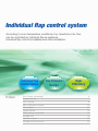
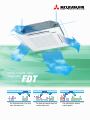
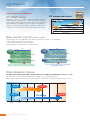
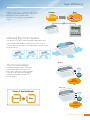
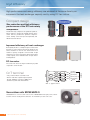
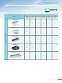
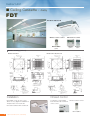
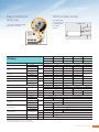
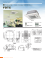
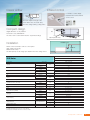
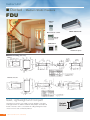
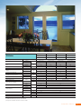
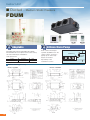
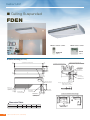
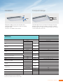
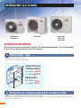
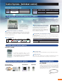
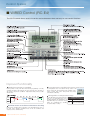
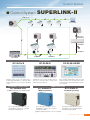
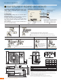
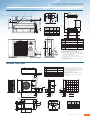
R410A
High Performance Air-Conditioning
FD series
Inverter Packaged Air-Conditioners
Individual flap control system
According to room temperature conditions, four directions of air flow
can be controlled by individual flap as preferred.
Individual flap control is available even after installation.
Individual Flap
Control System
Index
The Thinnest
Design
High
Efficiency
Our inverter technology 4
Product line up
7
FDT cassette
8
FDTC compact cassette
10
FDU ducted
12
FDUM ducted
14
FDEN ceiling suspended
16
Outdoor unit
18
Controls system
19
Outdoor unit dimensions
22
Ceiling Cassette -4wayIndoor units
FDT
For the person who is far away
from the indoor unit
For when one person feels hot
and the other cold
Can cool both the kitchen
and the guests
High Efficiency
QUICK CONTROL & HIGH EFFICIENCY
DC PAM inverter
DC compressor motor
Magnet Motor
Motor Efficiency(%)
An inverter system has a number of advantages over a constant
speed system. It’s variable speed compressor outputs can ensure
quick cooling or heating after start up and attains a set temperature
more quickly. The air conditioner can slow down the compressor
speed to save energy whilst keeping comfortable conditions. The
compressor is DC motor driven so it provides higher performance.
Improving
Improving
Induction Motor
Revolution speed
Low
New Inverter Control
(Vector control)
New Inverter Control has applied the new advanced technology of Vector control enabling:• Smooth operation from low to high speed
• Smooth Sine Voltage Wave form is achieved
• Energy efficiency has improved in low speed range
Time
Time
DC PAM
INVERTER
Room Temp.
PAM
CONVENTIONAL
INVERTER
Room Temp.
PWM
Set Temp.
Set Temp.
Even Temperature
DC PAM
INVERTER
Rated Capacity
ON
Compressor
(rps)
ON
CONVENTIONAL
Utmost comfort and energy efficiency achieved
with large output power and control optimisation
Rated Capacity
OFF
OFF
Compressor
(rps)
Less advanced technology does not address
the ON/OFF cycle issue.
Wide Operation Range
Heating and cooling operations are possible at an outdoor temperature as low as –15°C.
Our new advanced technology has improved the heating and cooling operation range.
Units can be installed when heating or cooling operation is required at low ambient conditions down to -15°C.
-15°C
Heating
-15°C
-20
4
+21°C
+46°C
Cooling
-10
0
High Performance Air C o n d i t i o n i n g
DC
PAM
INVERTER
PowerActiveModule
10
20
30
40
50
High
High Efficiency
Previous
New
3-core
2-core
New remote control RC-E4
New remote control for all indoor units
Non-polar 2 core wiring now used. Installation is
easier.
Individual flap control system
Four directions of air flow can be arranged by individual flap control.
Our new outlet design enables the right amount of air to reach all
corners of the room. Pressure loss caused by airflow in the indoor unit
has been reduced.
FDT60~71
The thinnest design
The heat exchanger has been re-designed
and energy efficient DC fan motors have
been used to enable us to reduce the height
of the indoor unit. Heat exchanger piping
modification and design increases heat
transfer efficiency.
270mm
246
mm
9%
reduction!!
FDT125~140
Shape of Heat exchanger
Current
New
365mm
298
mm
18%
reduction!!
P a c k a g e d A i r C o nditioners
5
High Efficiency
High performance and energy efficiency are achieved at the same time by an
increase in the heat exchanger capacity and by using DC fan
motors.
Non
Inverter
■ Cool Only Wall-split System -
Size reduction and high efficiency
performance of the DC twin rotary
compressor
The DC twin rotary compressor can operate at speeds as
high as 120 rps to achieve the required capacity. Vector
control and has provided the optimum compressor
control. Starting current has improved significantly and
vibration has been reduced.
Height at 342mm
Reduction in height by 22.3%
Reduction in volume by 44.1%
Height at 440 mm
Compact design
Outside diameter of shell
ø185mm
ø133mm
Former
compressor
New model
DC rotary compressor
Improved efficiency of heat exchanger
Re-designing the fins to a straight shape has reduced the
pressure loss of the air flow in the heat exchanger. A new
surface treatment on the fins has enhanced the frost
resistance capacity compared to former models. A high
speed fan motor has increased the airflow which allows
cooling capacity to be maintained even at high outdoor
air temperatures.
Former model
DC fan motor
New model
CnT terminal
CnT
A dry contact is fitted to each indoor unit
which is used when a signal output is required.
The CnT simpliflies connection to BMS, home
automation systems and external timers
XR2
XR3
XR4
XR5
XR1~5 : approx. DC12v
SRC50/60ZIX-S is common for both outdoor units of SRK50/60ZIX-S wall split systems, and 5.0
& 5.6kW of Inverter Packaged Air-Conditioners. The installation procedure is the same.
High Performance Air C o n d i t i o n i n g
XR4
XR5
New outdoor units SRC50/60ZIX-S
6
XR1
XR2
XR3
XR1
common
output1 (run)
output2 (heat)
output3 (comp on)
output4 (alarm)
in put
Power
source
The outdoor fan motor has improved efficiency by 60%
compared to former models.
Product line up
■ Cool Only Wall-split System Model
2.0
2.5
SRK-ZIX series ModelNEW
FDT Caseette
SRF-ZIX series
Floor
Standing
type
20ZIX-S
R410A
Capacity Range (kW : Rated cooling capacity)
3.5
4.0
5.0
5.6
5.0
6.0
7.1
25ZIX-S
35ZIX-S
50ZIX-S
25ZIX-S
35ZIX-S
50ZIX-S
6.0
10.0
6.3
7.1
12.5
14.0
60ZIX-S
NEW
HEAT
PUMP
DC
INVERTER
2.8
Non Inverter
FDTC Mini Cassette
SRK-ZE series
DC INVERTER
63ZE-S1
71ZE-S1
SRK-ZG series
HEAT PUMP
FDU Ducted
Model
SKM
20ZG-S
2.0
FDUM Ducted20ZG-S
25ZG-S
35ZG-S
2.2
2.5
2.8
3.5
22ZG-S
25ZG-S
28ZG-S
35ZG-S
50ZG-S
4.0
4.5
4.8
5.0
5.6
6.0
6.3
7.1
8.0
50ZG-S
Wall
mounted
type
60ZG-S
71ZG-S
SRRM
Ceiling
Concealed
type
INVERTER
Free-Multi
FDEN Under Ceiling
25ZF-S
35ZF-S
50ZF-S
60ZF-S
25ZF-S
35ZF-S
50ZF-S
60ZF-S
STM
4way ceiling
cassette type
600 x 600
Super Compact type
2 rooms
OUTDOOR UNIT
SCM
40ZG-S
45ZG-S
3 rooms
3 rooms
48ZG-S
60ZG-S
4 rooms
80ZG-S
P a c k a g e d A i r C o nditioners
7
Indoor Unit
■ Ceiling Cassette -
4way
FDT
FDT 60/71/100/125/140
Wireless remote control
Wired remote control
RCN-T-36W-E
(Option)
RC-E4
(Option)
RCH-E3
(Option)
Outline drawing (Unit:mm)
Model FDT 60,71
Model FDT 100,125,140
Installation
Infrared control
Detachable covers at each corner
allows for easy alignment and balance.
The panel does not need to be
removed. Installation time is reduced.
For wireless control simply
insert the infra-red receiver kit
on the corner.
wireless remote control
RCN-T-36W-E
8
High Performance Air C o n d i t i o n i n g
■Easy
Cool
OnlyofWall-split System
- Non
checking
700mm
DrainInverter
Pump
drain pan
The drain pump
can discharge up
to 700mm from
the ceiling
surface.
To check the drain pan simply
remove the corner lid.
Flexible hose
less than
700mm
FDT60ZIXVD
FDT Series
Power Supply
Capacity
Input
Energy Label
FDT71VNVD
Heating H1
Cooling T1
Heating H1
Cooling
Heating
FDT125VNVD
FDT140VNV
FDT60VD
FDT71VD
FDT100VD
FDT125VD
FDT140V
SRC60ZIX-S
FDC71VN
FDC100VN
FDC125VN
FDC140VN
5.6 (2.8~6.3)
7.1 (3.2~8.0)
10.0 (4.0~11.2)
12.5 (5.0~14.0)
14.0 (5.0~14.5)
6.7 (3.1~7.1)
8.0 (3.6~9.0)
11.2 (4.0~12.5)
14.0 (4.0~16.0)
16.0 ( 4.0~16.5)
1.57
1.90
2.76
4.05
4.98
1.85
2.07
2.74
3.77
4.57
2.5
2
1.5
1
2.5
2.5
3
2
Outdoor Unit
Cooling T1
FDT100VNVD
1 phase 230V 50Hz
kW
kW
Stars
Grandfathered
EER
Cooling T1
3.56
3,73
3.62
3.08
COP
Heating H1
3.62
3.86
4.08
3.71
3.5
Cooling T1
7.0
8.3
12.1
17.7
22.0
8.2
9.0
12.0
16.6
20.2
16
20
Current
Heating H1
Recommended Circuit Breaker
Sound Pressure Level (JIS C9612)
Sound Power Level (JIS C9612)
Amp
Amp
Indoor
dB
46-33-31-30
46-35-33-31
48
2.81
32
51-40-37-35
51-42-40-37
49
51-43-41-38
51
Outdoor
dB(A)
65
63
70
72
73
Airflow
Indoor
l/s
466-300-266-233
466-350-316-283
616-450-400-333
616-500-450-383
616-500-450-383
Panel
T-PSA-3AW-E
mm
External Dimensions (HXWXD)
Net Weight
Indoor
Outdoor
Indoor
Outdoor
mm
kg
Liquid line
Refrigerant Piping
Gas line
35 × 950 × 950
246 × 840 × 840
640 × 800 × 290
298 × 840 × 840
750 × 968 × 340
43
Unit 27 Panel 5.5
60
Pre-charged Amount
Maximum Piping Length
Controller
81
Ø6.35 (1/4”)
mm(in)
Ø9.52 (3/8”)
Ø12.7 (1/2”)
Ø15.88 (5/8”)
Connection Method
Refrigerant R410A
845 × 970 × 370
Unit 24 Panel 5.5
Flare
kg
1.4
m
15
m
30
2.95
3.8
30
50
RC-E4 or RCN-T-36W-E
For additional information please reference 10.PAC.DB.142A
Sound pressure level indicates the value in an anechoic chamber
P a c k a g e d A i r C o nditioners
9
Indoor Unit
■ Cassette - 4way Compact (600x600mm)
■ Cool Only Wall-split System - Non Inverter
FDTC
FDTC 50
Wireless remote control
RCN-TC-24W-ER
(Option)
Outline drawing (Unit:mm)
10
High Performance Air C o n d i t i o n i n g
Wired remote control
RC-E4
(Option)
High Efficiency
Clearer airflow
Infrared control
■ Cool Only Wall-split System -
For wireless control simply
Non Inverter
insert the infra-red receiver kit
on the corner.
The new shape and angle of the
louver directs the air current away
from the ceiling reducing ceiling stains.
Compact design
248
Height dimension is only 248mm
Panel size is only 700x700mm.
The indoor unit is 570x570mm ideal for suspended ceilings.
Opening for exit wiring
Flexible hose
Installation
Wired or infra-red wireless remote control option.
Light weight only18.5kg
600mm Drain Pump
The drain pump can discharge up to 600mm from the ceiling surface.
600mm
FDTC50ZIXVD
FDTC Series
FDTC50VD
SRC50ZIX-S
Power Supply
Capacity
Input
Energy Label
Outdoor Unit
Cooling T1
Heating H1
Cooling T1
Heating H1
Cooling
Heating
1phase 230V 50Hz
kW
kW
Stars
5.0 (2.2~5.6)
5.4 (2.5~6.3)
1.56
1.45
2
2.5
EER
Cooling T1
3.205
COP
Heating H1
3.724
Current
Cooling T1
Heating H1
Recommended Circuit Breaker
Sound Pressure Level (JIS C9612)
Sound Power Level (JIS C9612)
Amp
Amp
Indoor
Outdoor
dB
6.9
6.4
16
47-42-36-32
47
Outdoor
dB(A)
62
Airflow
Indoor
l/s
225-191-150-133
Panel
TC-PSA-25W-E
mm
External Dimensions (HXWXD)
Net Weight
Indoor
Outdoor
Indoor
Outdoor
Liquid line
Refrigerant Piping
Gas line
mm
kg
mm(in)
Connection Method
Refrigerant R410A
Maximum Piping Length
Controller
Pre-charged Amount
35 × 700 × 700
248 × 570 × 570
640 × 800 × 290
Unit 15 Panel 3.5
43
Ø6.35 (1/4”)
Ø12.7 (1/2”)
Flare
kg
1.4
m
15
m
30
RC-E4 or RCN-TC-24W-ER
For additional information please reference 10.PAC.DB.142A
Sound pressure level indicates the value in an anechoic chamber
P a c k a g e d A i r C o nditioners
11
Indoor Unit
■ Ducted -
Medium Static Pressure
FDU
RCH-E3
(Option)
Wired remote control
FDU71/100/125/140
RC-E4
(Option)
RCN-KIT3-E
Return air option
Outline drawing (Unit:mm)
FDU71
FDU100,125,140
Quiet, Lightweight and Compact
The FDU71 noise level is only 37dB on low fan. Weight is only 40kg
and height 297mm. In addition a 600mm drain pump is mounted in all
models. The indoor unit is concealed in the ceiling making it the ideal
choice for homes and commercial premises.
12
High Performance Air C o n d i t i o n i n g
Height
297mm
High Efficiency
FDU Series
Power Supply
Capacity
Input
FDU71VNVD
FDU100VNVD
FDU125VNVD
FDU140VNV
FDU71VD
FDU100VD
FDU125VD
FDU140V
FDC71VN
FDC100VN
FDC125VN
FDC140VN
Outdoor Unit
Cooling T1
Heating H1
Cooling T1
Heating H1
1 phase 230V 50Hz
kW
kW
7.1 (3.2~8.0)
10.0 (4.0~11.2)
12.5 (5.0~14.0)
14.0 (5.0~14.5)
8.0 (3.6~9.0)
11.2 (4.0~12.5)
14.0 (4.0~16.0)
16.0 (4.0~16.5)
2.08
2.88
4.04
4.95
2.21
2.99
3.79
4.43
EER
Cooling T1
3.41
3.47
3.09
2.82
COP
Heating H1
3.61
3.74
3.69
3.61
Cooling T1
9.2
12.7
17.8
21.7
10.2
13.1
16.6
19.5
Current
Heating H1
Recommended Circuit Breaker
Sound Pressure Level (JIS C9612)
Sound Power Level (JIS C9612)
Airflow
External Static Pressure
External Dimensions (HXWXD)
Net Weight
Amp
Indoor
Outdoor
Outdoor
Indoor
Indoor
Outdoor
Indoor
Outdoor
Liquid line
Refrigerant Piping
Amp
Gas line
dB
20
Hi :41 Lo : 37
Hi : 42 Lo : 37
48
49
Pre-charged Amount
Maximum Piping Length
Controller
Hi : 43 Lo : 38
63
70
l/s
Hi : 333 Lo : 283
Hi : 566 Lo : 450
Pa
60/130 @ 333 l/S
60/130 @ 566 L/S
mm
kg
Hi : 43 Lo : 38
51
dB(A)
72
73
Hi : 700 Lo : 558
60/130 @ 700 L/S
297 × 850 × 650
350 × 1,370 × 650
750 × 968 × 340
845 × 970 × 370
40
63
60
81
Ø9.52 (3/8”)
mm(in)
Ø15.88 (5/8”)
Connection Method
Refrigerant R410A
32
Flare
kg
m
m
2.95
3.8
30
50
RC-E4
For additional information please reference 10.PAC.DB.142A
Sound pressure level indicates the value in an anechoic chamber
P a c k a g e d A i r C o nditioners
13
Indoor Unit
■ Ducted -
Medium Static Pressure
FDUM
Wired remote control
RCN-KIT3-E
1 Adaptable
(Option)
2 600mm Drain Pump
Selectable static pressure and Flexible duct design
with selectable air suction (direct suction /duct suction)
can meet a wide range of installations.
Static pressure Pa
model
Standard
Max
50/60
50
85
Drain can be discharged
upwards by 600mm from the
ceiling surface. It allows a
piping layout with a high
degree of freedom
depending on the
installation location.
Outline drawing(Unit:mm)
14
RCH-E3
(Option)
Point
Point
Model FDUM50
RC-E4
Models FDUM60
Flexible hose
less than
600mm
High Efficiency
Indoor Unit
FDUM Series
FDUM50ZIXVD
FDUM60ZIXVD
FDUM50VD
FDUM60VD
SRC50ZIX-S
Power Supply
Outdoor Unit
Cooling T1
Capacity
Heating H1
Cooling T1
Input
Heating H1
SRC60ZIX-S
1 phase 230V 50Hz
kW
kW
5.0 (2.2~5.6)
5.6 (2.8~6.3)
5.4 (2.5~6.3)
6.7 (3.1~7.1)
1.52
1.86
1.41
1.96
EER
Cooling T1
3.28
3.01
COP
Heating H1
3.82
3.41
Cooling T1
6.7
8.2
Current
Heating H1
Recommended Circuit Breaker
Amp
6.3
Amp
Indoor
Sound Pressure Level (JIS C9612)
Outdoor
Sound Power Level (JIS C9612)
Outdoor
dB
9
16
35-34-31-28
38-34-31-28
47
48
dB(A)
62
65
300-266-250-233
Airflow
Indoor
l/s
233-216-200-183
External Static Pressure
Indoor
Pa
85 @ 233 l/s
85 @ 300 l/s
299 × 750 × 635
299 × 950 × 635
Indoor
External Dimensions (HXWXD)
Outdoor
Indoor
Net Weight
Outdoor
Liquid line
Refrigerant Piping
Gas line
mm
kg
mm(in)
Connection Method
Refrigerant R410A
Pre-charged Amount
Maximum Piping Length
Controller
640 × 800 × 290
34
40
43
Ø6.35 (1/4”)
Ø12.7 (1/2”)
Flare
kg
1.4
m
15
m
30
RC-E4
For additional information please reference 10.PAC.DB.142A
Sound pressure level indicates the value in an anechoic chamber
P a c k a g e d A i r C o nditioners
15
Indoor Unit
■ Ceiling Suspended
FDEN
Wired remote control
Wireless remote control
RC-E4
RCN-E1R
(Option)
(Option)
Outline drawing (Unit:mm)
a (Suspension bolts pitch)
24
290(Suspension bolts pitch)
5
24
135
Holes for suspension bolts
(M8 to M10X 4pcs.Not included)
410
145
b
40
52
Liquid piping
e
d
173
68
Gas piping
40
Air outlet
53
109
c
690
Drain hole
connection(1)
(VP20)
195
235
271
16
135
Space for installation and service
100
or more
Dimension Table
FDEN100VNV
a
b
c
d
e
1572
1540
1620
255
250
High Performance Air C o n d i t i o n i n g
53
110
Drain hole
connection(1)
(VP20)
model
10
75 Liquid piping
Gas piping
Air inlet grille
Note(1) The slope of drain piping
inside the unit is able
to take incline of 10mm.
300 or more
Drain hole
connection(1)
(VP20)
76
308
Indication board
150
or more
Obstacles
5
or more
High Efficiency
Installation
Compact design
Up
Height
250mm
Right
Rear
The FDE height starts at just 250mm and weighs just 63kg’s
allowing for quick and easy installation. The unit is compact
and fits neatly on the ceiling. The modern design with rounded
corners lends style to the room.
Refrigeration piping can be set in three directions
and the drain pipe arranged in two directions making
installation easier.
The unit is serviceable from the bottom.
FDEN100VNVD
FDEN Series
FDEN100VD
FDC100VN
Power Supply
Capacity
Input
Energy Label
Outdoor Unit
Cooling T1
Heating H1
Cooling T1
Heating H1
Cooling
Heating
1 phase 230V 50Hz
kW
kW
Stars
10.0 (4.0~11.2)
11.2 (4.0~12.5)
2.85
2.97
2
2.5
EER
Cooling T1
3.508
COP
Heating H1
3.771
Current
Cooling T1
Heating H1
Recommended Circuit Breaker
Sound Pressure Level (JIS C9612)
Sound Power Level (JIS C9612)
Airflow
External Dimensions (HXWXD)
Net Weight
Amp
Indoor
Outdoor
dB
Maximum Piping Length
Controller
13.0
32
P-Hi : 46 Hi : 44 Me : 41 Lo : 39
49
dB(A)
70
Indoor
l/s
P-Hi :466 Hi :433 Me :383 Lo :350
Indoor
Outdoor
Indoor
Outdoor
Gas line
mm
kg
mm(in)
Connection Method
Refrigerant R410A
12.5
Outdoor
Liquid line
Refrigerant Piping
Amp
Pre-charged Amount
250 × 1,620 × 690
845 × 970 × 370
63
81
Ø9.52 (3/8”)
Ø15.88 (5/8”)
Flare
kg
3.8
m
30
m
50
RC-E4 or RCN-E1R
For additional information please reference 10.PAC.DB.142A
Sound pressure level indicates the value in an anechoic chamber
P a c k a g e d A i r C o nditioners
17
Outdoor Unit
OUTDOOR UNIT (4.0-14.0kW)
SRC50ZIX-S
SRC60ZIX-S
FDC71VN
FDC100VN
FDC125VN
FDC140VN
Installation workability
Enhanced installation workability thanks to the extended pipe length – one of the longest
levels in the industry and pre-charged refrigerant.
1 Piping length – 50m
Point
Piping length can be extended up to 50m for
single type, which allows wider design flexibility.
Height difference
(Outdoor>indoor)
5.0 ~ 6.0kW
7.1~14.0kW
20m
30m
Piping length
5.0 ~ 6.0kW : 30m
7.1~14.0kW : 50m
2 Refrigerant pre-charged piping length extending to 30m
Point
Refrigerant pre-charged piping length extends up to 30m. (5.0 ~ 6.0kW: up to15m)
This eliminates the need to add refrigerant on site, which sets it free from trouble of excessive or insufficient charging of refrigerant, and allows
carrying out the installation smoothly.
18
Control System (Individual
High Efficiency
Control)
Control Systems [Individual control]
Remote Control line up
■ Cool Only Wall-split System indoor unit
wired
all models
remote control
RC-E4
RCH-E3
wireless
control
Non Inverterremote
RCN-T-36W-E
indoor unit
FDT
FDTC
FDUM, FDU
FDEN
RCN-TC-24W-ER
RCN-KIT3-E
RCN-E1R
Wired remote control with weekly timer (option)
RC-E4
Run hour meters to facilitate maintenance checking
RC-E4 stores operation data when an anomaly occurs and indicates the error
on the LCD. It also displays cumulative operation hours of the air conditioner
and compressor since commissioning.
The RC-E4 controller
enables extensive access to
service and maintenance
technical data combined
with easy to use functions
and a clear LCD display.
Weekly timer function as standard
RC-E4 provides (as a standard feature) a weekly timer, which allows
one-week operation schedules to be registered. A user can specify up to
four times a day to start/stop the air conditioner. (Temperature setting is
also possible with the timer).
Timer operation
Room temperature controlled
by the remote control sensor
The temperature sensor is housed in the top
section of the remote control unit. This
arrangement has improved the sensitivity of the
remote control unit’s sensor, which permits more
finely controlled air conditioning.
Changeable set temperature ranges
RC-E4 allows the upper and lower limits of a set temperature range to be
specified separately.
By adjusting a set temperature range, you can ensure energy saving air
conditioning by avoiding excessive cooling or heating.
Changeable range
Upper limit
20~30°C(effective for heating operation)
Lower limit
18~26°C(effective for non-heating operation)
Simple remote control (option)
RCH-E3 (wired)
Up to 16 units
Considering specialized usage in hotel
rooms, control buttons are limited only to
minimum required functions such as ON/OFF,
mode, temperature setting and fan speed. It
is really simple and easy to use.
It can control up to 16 units individually by pressing the AIR CON No. button.
AUTO restart
This function allows starting the air conditioner automatically when power
supply is restored after power failure or by turning on the power switch.
Wireless remote control (option)
Thermistor (option)
For wireless control simply insert the infrared receiver kit on a corner of the panel.
SC-THB-E3
RCN-T-36W-E,
RCN-TC-24W-ER
In case the sensor in the indoor units or the remote
control sensor can not sense the room temperature
correctly, or individual remote control in each room is
not required but only a censor is required (as when
center control system is in place), install SC-THB-E3
at a proper place in the room.
RCN-KIT3-E
RCN-E1R
19
Control System
■ WIRED Control (RC-E4)
The RC-E4 control allows access to service and maintenance data and easy to use comfort functions.
Improved Functionality
Weekly timer function as standard
RC-E4 provides a 7day 24hr timer which allows programming of weekly
operating schedules to be registered. The user can specify up to four times a
day to start / stop the air conditioner. Temperature setting is also possible
with the timer.
Room temperature controlled by the remote control sensor
The temperature sensor is located in the top section of the
remote control unit. This has improved the sensitivity of the
remote controls heat sensor and permits more finely
controlled air conditioning.
Changeable set temperature range
The RC-E4 allows for the upper and lower
limits of a set temperature range to be
specified separately. By adjusting the set
temperature range you can ensure energy
saving air conditioning by avoiding
excessive heating or cooling.
Run hour meters to facilitate maintenance checking
RC-E4 stores operation when an anomaly occurs and indicates the error on
the LCD. It also displays cumulative hours of the air conditioner and
compressor since commissioning.
20
High Performance Air C o n d i t i o n i n g
Changeable range
Upper
20~30°C
(effective for heating operation)
limit
18~26°C
Lower
(effective for non-heating operation)
limit
Control System
■ Control System SUPERLINK-II
Control
System SUPERLINKKX6 series
SC-SL1N-E
RAC series
(SRK50/60ZHX-S)
SC-BIKN-E
SC-ADN-E
SC-SL2N-E
SC-ADN-E
SC-ADN-E
Central Control
SC-SL1N-E
SC-SL2N-E
SC-SL3N-AE/BE
Start/stop control of up to 16 indoor units is
possible either individually or collectively. With
simple operations, you can effect centralized
control.
Centralized control of up to 64 indoor units. It
can allow connection with a weekly timer
without using any interface.
Easy operation realized with a large color LCD
and touch panel. Up to 128 indoor units can be
controlled, when three SUPERLINK-II systems
are connected.
PC windows central control
SC-WGWN-A/B*
(SC-WGWN-B is with electric power calculation function)
Up to 96 groups (64 indoor unit x 2
SUPERLINK-II systems) are controlled
through an internet browser.
BMS interface unit
SC-BGWN-A*
(BACnet gateway)
Up to 96 groups (64 indoor unit x 2
SUPERLINK-II systems) are controlled
centrally from a BMS.
SC-LGWN-A*
(LonWorks gateway)
Up to 96 indoor units (48 indoor unit x 2)
are linked as an open network. Centrally
controlled through LonWorks.
*Additional engineering service cost etc. is required.
P a c k a g e d A i r C o nditioners
21
Control System
■
SUPERLINK
E BOARD (SC-ADN-E)
SUPERLINK
E BOARD (SC-ADN-E)
(2) Wiring connection diagram
This board is used when conducting control of the
single package (wired remote control unit) 1-type
series using a network option (SC-SL1N-E,
SC-SL2N-E, etc).
Run
Abnormal
(1) Functions
Master/Sub
address
SW1
Outdoor unit
Network address setting switches
[000]-(127)
Connected to the remote controller terminals (no
polarity) (the length should be 600 m or shorter)
200 m or shorter
0.5 mm2 x 2 cores
0.75 mm2 x 2 cores
300 m or shorter
1.25 mm2 x 2 cores
400 m or shorter
2.0 mm2 x 2 cores
600 m or shorter
Internal/external Crossing
Inside Inside Inside Inside
Remote control
X Y
SL E
Board
R
R
Network A B
options
• Transmit the information of plural “Master” units to the network.
• Transmit the abnormalities of the “Slave” units to the network.
Setting the plural “Master/Slave” units with the dip SW of the printed circuit board.
Network
options
Setting the “Master/Slave” remote controls with the dip SW of the remote control board.
Plural Controls by Multiple Remote Controls. Mixture of Multiple Units
Outdoor unit
Outdoor unit
Internal/external Crossing
Inside Inside Inside Inside
R
SW2
Y
Outdoor unit
Indoor unit
X Y
SL E
Board
X
White
Y
Plural Controls by Multiple Remote Controls. Mixture of Multiple Units
Internal/external Crossing
SL E Board
X Y
A B
SW3
B
Black
X
ON
OFF
A
Blue
B
LED3
Basic Connections
LED2
(a) Transmits the settings from the network option
to the indoor units.
(b) Returns the priority indoor unit data in response
to a data request from the network option.
(c) Inspects the error status of connected indoor
units and transmits the inspection codes to the
network option.
(d) A maximum of 16 units can be controlled (if in
the same operation mode).
Blue
A
SL E board
Connected to the terminals for
Superlink signal lines
MVVS 0.75 - 1.25mm2
Inside Inside Inside
R
Outdoor unit
Internal/external Crossing
Internal/external Crossing
Inside Inside
SL E
Board
R
OUTDOOR UNIT DIMENSIONS
Network
options
Wireless Kit
Outdoor unit
Internal/external Crossing
SL E
Board
R
Without Remote Control
Set up “000” to “127” using address switch on the SL E board.
SRC 50ZIX-S, 60ZIX-S (unit:mm)
Network
options
Inside Inside
Set the SL E board dip SW to
“Master” SW3-1 ON.
The network option SLA-1-E,
SL1N-E is not allowed (This
will disturb switching of the
operation mode)
SL E
Board
Network
options
148.4
Intake
640
Check joint
42.5
93
12.4
High Performance Air C o n d i t i o n i n g
E
71.2
14.8
201
351.6
24.3
312.5
43.5
290
83.5
17.9
510
800
22
40°
327.3
89
A
Mark
A
B
D
E
L4
Service
space
L1
B
40°
50.6
12
L3
Intake
33.5
outlet
D
Wireless
remote control
Terminal block
L2
327.3
Wireless Kit
Examples of
installation
Dimensions
L1
L2
L3
L4
Item
Refrigerant gas side pipe connection tap
Refrigerant liquid side pipe connection tap
Drain discharge port
Anchor bolt hole
1
2
3
Open 280 280
100
75 Open
100
80
80
250 Open 250
ø12.7(flare)
ø6.35(flare)
ø20.5x5places
M10x4places
Notes:
(1) It must not be surrounded by walls on the four sides.
(2) The unit must be fixed with anchor bolts.An anchor bolt must not protrude more than
15mm.
(3) Where the unit is subject to strong winds, lay it in such a direction that the blower outlet
faces perpendicularly to the dominant wind direction.
(4) Leave a 1m or larger space above the unit.
(5) A wall in front of the blower outlet must not exceed the units height.
(6) The unit name plate is attached on the lower right corner of the front panel.
Outdoor Unit Dimensions
OUTDOOR UNIT DIMENSIONS
FDC71VN (unit:mm)
D
150
L4
D
Intake
19
15
Intake
L3
L2
532
223
60
outlet
47.5
L1
580
310
47
Minimum installation space
380
418
340
Service
space
E
Dimensions
150
580
880
25.8
29.8
150
L1
L2
L3
L4
19
2-ø15
61
87.9
1
2
3
Open
300
100
250
Open
250
150
250
500
Open
100
250
222
150
40
61
Examples of
installation
40
20
Terminal block
Mark
A
B
C
D
E
F
B
25.5
750
165.5
48.5
30
103.3
340
40
380
20
Item
Refrigerant gas side pipe
ø15.88(flare)
connection tap
Refrigerant liquid side pipe
ø9.52(flare)
connection tap
Pipe/cable draw-out port
ø20.3x3places
Drain discharge port
Anchor bolt hole
M10x4places
ø30.3x3places
Cable draw-out port
Notes:
(1) It must not be surrounded by walls on the four sides.
(2) The unit must be fixed with anchor bolts.An anchor
bolt must not protrude more than 15mm.
(3) Where the unit is subject to strong winds, lay it in such
a direction that the blower outlet faces perpendicularly
to the dominant wind direction.
(4) Leave a 1m or larger space above the unit.
(5) A wall in front of the blower outlet must not exceed the
units height.
(6) The unit name plate is attached on the lower right
corner of the front panel.
30
24.1
55
A
FDC100VN, 125VN, 140VN
Mark
A
40
B
100
51
36
B
C
D
E
F
A
Item
Refrigerant gas side pipe
connection tap
Refrigerant liquid side pipe
connection tap
Pipe/cable draw-out port
Drain discharge port
Anchor bolt hole
Cable draw-out port
ø15.88(flare)
ø9.52(flare)
ø20.3x3places
M10x4places
ø30.3x3places
Notes:
(1) It must not be surrounded by walls on the four sides.
(2) The unit must be fixed with anchor bolts.An anchor bolt
must not protrude more than 15mm.
(3) Where the unit is subject to strong winds, lay it in such a
direction that the blower outlet faces perpendicularly to
the dominant wind direction.
(4) Leave a 1m or larger space above the unit.
(5) A wall in front of the blower outlet must not exceed the
units height.
(6) The unit name plate is attached on the lower right corner
of the front panel.
Terminal block
B
A
50
150
110
195
F
50
50
55
C
279
242
110
50
10
195
F
52
15
27
40
190
580
15
103
38
20
40
L3
D
Intake
VIEW A
Examples of
installation
L4
Intake
370
410
L2
C
388
50
15
L1
262
15
200
60
40
60
55
20
60
C
C
50
970
E
70
845
A
outlet
Service
space
Dimensions
L1
L2
L3
L4
1
2
3
Open Open 500
300
5 Open
150 300 150
5
5
5
Minimum installation space
P a c k a g e d A i r C o nditioners
23
Before starting use
Heating performance
Refrigerant leakage
The heating performance values (kW) described in catalog are the values
obtained by operating at an outdoor temperature of 7C and indoor temperature
of 20C as set forth in the ISO Standards. As the heating performance decreases
as the outdoor temperature drops, if the outdoor temperature is too low and the
heating performance is insufficient, use other heating appliances as well.
The refrigerant (R410A) used for Air conditioner is non-toxic and nonflammable
in its original state.
However, in consideration of a state where the refrigerant leaks into the room,
measures against refrigerant leaks must be taken in small rooms where the
tolerable level could be exceeded. Take measures by installing ventilation
devices, etc.
Indication of sound values
The sound values are the values (A scale) measured in a chamber such as an
anechoic chamber following the ISO Standards. In the actual installation state,
the value is normally larger than the values given in the catalog due to the effect
of surrounding noise and echo. Take this into consideration when installing.
Use in snowy areas
Take the following measures when installing the outdoor unit in snowy areas.
Snow prevention
Install a snow-prevention hood so that the snow does not obstruct the air intake
port or enter and freeze in the outdoor unit.
Use in oil atmosphere
Avoid installing this unit in as atmosphere where oil scatters or builds up, such
as in a kitchen or machine factory.
If the oil adheres to the heat exchanger, the heat exchanging performance will
drop, mist may be generated, and the synthetic resin parts may deform and
break.
Use in acidic or alkaline atmosphere
If this unit is used in acidic atmosphere such as hot spring areas having high
level of sulfuric gases or in alkaline atmosphere including ammonia or calcium
chloride, places where the exhaust of the heat exchanger is sucked in, or at
coastal areas where the unit is subject to salt breezes, the outer plate or heat
exchanger, etc., will corrode. Please ask a dealer or specialist when you use an
air conditioner in places differing from a general atmosphere.
Use in places with high ceilings
If the ceiling is high, install a circulator to improve the heat and air flow
distribution when heating.
Snow piling
In areas with heavy snow fall, the piled snow could block the air intake port. In
this case, a frame that is 50cm or higher than the estimated snow fall must be
installed underneath the outdoor unit.
Automatic defrosting device
If the temperature is low, and the humidity is high, frost will stick to the heat
exchanger of the outdoor unit. If use is continued, the heating performance will
drop.
The “Automatic defrosting device” will function to remove this frost.
After heating for approx, three to ten minutes, it will stop, and the frost will be
removed. After defrosting, hot air will be blown again.
Servicing the air-conditioner
After the air-conditioner is used for several seasons, dirt will build up in the
air-conditioner causing the performance to drop. In addition to regular servicing,
we recommend the maintenance contract (charged for) by a specialist.
Safety Precautions
Air-conditioner usage target
Installation
The air-conditioner described in this catalog is a dedicated cooling/heating
device for human use.
Do not use it for special applications such as the storage of foodstuffs, animals
or plants, computer server rooms, precision devices or valuable art, etc.
This could cause the quality of the items to drop, etc.
Do not use this for cooling vehicles or ships. Water leakage or current leaks
could occur.
Always commission the installation to a dealer or specialist. Improper
installation will lead to water leakage, electric shocks and fires.
Make sure that the outdoor unit is stable in installation. Fix the unit to stable
base.
Before use
Always read the “User,s Manual” thoroughly before starting use.
Usage place
Do not install in places where combustible gas could leak or where there are
sparks.
Installation in a place where combustible gas could be generated, flow or
accumulate, or places containing carbon fibers could lead to fires.
Only persons that are qualified and licensed are permitted to install and service products that contain refrigerants in Australia, go to www.arctick.org.
Suitable access for service must be provided in compliance with industry standards and local regulations.
ABN 92 133 980 275
National Contact Information:
Phone: 1300 138 007
Fax: 1800 644 329
www.mhiaa.com.au
New South Wales & Head Office
Victoria
Queensland
Western Australia
9C Commercial Road
Kingsgrove NSW 2208
PO Box 318 Kingsgrove NSW 1480
10 Derby Street
Collingwood VIC 3066
2/27 Kingtell Place
Geebung QLD 4034
PO Box 124, Virginia QLD 4014
1 Frederick Street
Belmont WA 6104
PO Box 667 Belmont WA 6104
MRE SPARE PARTS
www.mrespareparts.com.au
ISO9001
Fax: +61 (0) 2 9600 8044
ISO14001
BIWAJIMA PLANT
Mitsubishi Heavy Industries, Ltd.
Air-conditioning & Refrigeration Systems Headquarters
Certified ISO 9001
Certificate number : JQA-0709
MITSUBISHI HEAVY INDUSTRIESMAHAJAK AIR CONDITIONERS CO., LTD.
Certified ISO 9001
Certificate Number : 04100 1998 0813
Our Air Conditioning &
Refrigeration Systems
Headquarters has been
assessed and found to
comply with the
requirements of
ISO14001.
ISO 14001
Certificate 04104 1998 0813 E5
BIWAJIMA PLANT
Mitsubishi Heavy Industries, Ltd.
Air-conditioning & Refrigeration Systems Headquarters
Certified ISO 14001
Certificate number : JQA-EM0256
MITSUBISHI HEAVY INDUSTRIESMAHAJAK AIR CONDITIONERS CO.,LTD.
Certificate Number : 04104 1998 0813 E5
Because of our policy of continuous improvement, we reserve the right to make changes in all specifications without notice. E&OE.
MHIAA185_PAC FD series Aug 2010
Our Air Conditioning &
Refrigeration Systems
Headquarters is an ISO9001
approved factory for residential
air conditioners and
commercial-use air
conditioners (including heat
pumps).
Tel: +61 (0) 2 9600 7444