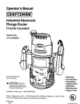
1
Acorn A3010, A3020 and A4000
Module Level Service Manual
Copyright © Acorn Computers Limited 1993
Published by Acorn Computers Technical Publications Department
Neither the whole nor any part of the information contained in, nor the product described in this manual may be adapted
or reproduced in any material form except with the prior written approval of Acorn Computers Limited.
The products described in this manual, and products for use with it are subject to continuous development and
improvement. All information of a technical nature and particulars of the products and their use (including the information
and particulars in this manual) are given by Acorn Computers Limited in good faith. However, Acorn Computers Limited
cannot accept any liability for any loss or damage arising from the use of any information or particulars in this manual, or
any incorrect use of the products. All maintenance and service on the products must be carried out by Acorn Computers'
authorised dealers or Approved Service Centres. Acorn Computers Limited can accept no liability whatsoever for any
loss or damage caused by service, maintenance or repair by unauthorised personnel.
This product is not intended for use as a critical component in life support devices or any system in which failure could
be expected to result in personal injury.
If you have any comments on this manual, please complete the form at the back of the manual and send it to the
address given there.
ACORN, ARCHIMEDES and ECONET are trademarks of Acorn Computers Limited.
ARM is a trademark of Advanced RISC Machines Limited.
Published by Acorn Computers Limited
ISBN 1 85250 109 X
Part number 0494,059
Issue 1, Sep 1993
Contents
About this manual
v
Part 1- Fault diagnosis and repair
1-1
Introduction
Test equipment required
Checking a 'dead' computer
Action if PSU fails
Action if main PCB fails
What to do next
Checking a partly working computer
Before the tests
Safety considerations
Part 2 - Disassembly and assembly
Introduction
A3010/3020
Removing the top cover
Removing the keyboard
Removing the metal safety case
Removing the floppy drive
Removing the hard disc
Removing the speaker
Removing the PCB
A4000
Removing the top cover
Removing the speaker
Removing the Drive Tray
Removing the PCB
Removing the front plastic moulding
Removing the PSU
Removing the floppy drive
Removing the hard disc
Main unit assembly
Power supply unit
Speaker
Disc drives
PCB
Keyboard and Mouse
1-1
1-1
1-1
1-3
1-3
1-4
1-4
1-5
1-5
2-1
2-1
2-1
2-1
2-1
2-1
2-2
2-2
2-2
2-2
2-3
2-3
2-3
2-3
2-3
2-3
2-4
2-4
2-4
2-4
2-4
2-4
2-4
2-4
2-4
Appendix A - Mouse test jig template
A-1
Appendix B - Serial port loopback plug
B-1
Appendix C - Earth continuity testing
C-1
Contents
Issue 1, October 1993
iii
A3010, A3020 and A4000
Module Level Service Manual
Equipment required
Before testing
Test procedure for the A4000
Test procedure for the A3010/A3020
Appendix D - DC insulation testing - class 1
UK information only
Equipment required
Before testing
Test procedure
D-1
D-1
D-1
D-1
D-1
Appendix E - Software testing
E-1
About the tests
How to operate the menu system
Connecting the customers equipment
Running the test software
After the tests
Performing safety tests
Retesting the unit
Switching off the equipment
Disconnecting the equipment
Packing
Individual Functional tests
Audio tests
Battery backed RAM test
Disc interface test
External port tests
Hard disc exerciser
Hard disc initialiser
Hardware check
IDE hard disc drive interface test
Joystick test
Keyboard and mouse tests
Memory test
Real time test
UHF modulator test
Video tests
Test report
Appendix F - Tools for software testing
Backing up the test disc
Validating the test equipment
Creating a test IDE hard disc
Replacing the customer's hard disc
Saving the customer's CMOS RAM settings
Restoring the CMOS RAM settings
iv
C-1
C-1
C-1
C-2
Issue 1, October 1993
E-1
E-1
E-2
E-2
E-3
E-3
E-4
E-4
E-4
E-4
E-4
E-4
E-5
E-5
E-6
E-7
E-7
E-7
E-8
E-8
E-9
E-10
E-10
E-11
E-11
E-12
F-1
F-1
F-1
F-1
F-2
F-2
F-2
Contents
About this manual
This manual is a module level service manual for the
Acorn A30101A3020 and A4000 series computers. It is
intended as a guide for suppliers at Acorn Service Centres
to enable them to trace and repair faults at a module level.
Suppliers are not expected to undertake repairs at a
component level, as surface mount technology is used on
the printed circuit boards of the A3010/A3020 and A4000
computers. Any modules which require component level
repairs should be sent to an Acorn Authorised Central
Service Workshop.
This manual supplements the basic information given on
system hardware in the Welcome Guide and Technical
Reference Manual (available for separate purchase).
The operating system is covered at the user level in the
RISC OS User Guide, supplied with certain models (also
available for separate purchase). Programmers and users
requiring a greater depth of information about RISC
OS will also need the following manual:
RISC OS Programmer's Reference Manual
(a boxed set)
This manual is available from Acorn authorised suppliers.
Full details on the Acorn ARM chip set used in the
workstation are given in the Acorn RISC Machine (ARM)
Family Data Manual, ISBN 0-13-781618-9, available from:
VLSI Technology, Inc.
Application Specific Logic Products Division
8375 South River Parkway
Tempe, AZ 85284
USA
602-752-8574
or from the VLSI national distributor.
Contents
Issue 1, October 1993
v
A3010, A3020 and A4000
vi
Module Level Service Manual
Issue 1, October 1993
Contents
Part 1- Fault diagnosis and repair
Introduction
Test equipment required
This chapter is a guide to the diagnosis and repair at a
modular level of basic faults in the Acorn A3010, A3020
and A4000 series computer systems.
•
It consists of algorithms to enable you to trace and
remedy faults in a 'dead' computer, followed by
instructions for running the Acorn functional test
software, which is designed to isolate faults in a
computer which is partly working.
Note: Throughout this chapter the acronym UUT is used
to mean Unit Under Test and the acronym CSW to mean
Central Service Workshop.
SAFETY CONSIDERATIONS
WHENEVER ANY SERVICE OR UPGRADE IS
PERFORMED, ENSURE THAT ALL THE FUNCTIONAL
TESTS AND SAFETY TESTS AS DESCRIBED IN THIS
SECTION ARE CARRIED OUT.
FULL FUNCTIONAL AND SAFETY TESTS SHOULD BE
APPLIED IRRESPECTIVE OF THE ORIGINAL FAULT OR
WORK PERFORMED. FOR DETAILS REFER TO Appendix
C - Earth continuity testing AND Appendix D - DC insulation
testing - class 1.
FAILURE TO CARRY OUT THE TESTS IN FULL MAY
RESULT IN AN UNSTABLE OR UNRELIABLE UNIT BEING
RETURNED TO THE CUSTOMER.
DANGER
BEFORE ATTEMPTING TO OPEN THE COMPUTER OR
EXCHANGE EITHER THE PSU (POWER SUPPLY UNIT)
OR PCB (PRINTED CIRCUIT BOARD), ENSURE THAT
YOU HAVE READ AND FULLY UNDERSTOOD ALL THE
INSTRUCTIONS IN Part 2 - Disassembly and assembly. IN
PARTICULAR, ENSURE THAT YOU DISCONNECT THE
COMPUTER, MONITOR AND PERIPHERALS FROM THE
POWER OUTLET.
UNDER NO CIRCUMSTANCES SHOULD ANY ATTEMPT
BE MADE TO REPAIR OR MODIFY THE PSU. ANY
ATTEMPT TO DO SO WILL INVALIDATE THE ORIGINAL
SAFETY TESTS APPLIED AT MANUFACTURE AND MAY
CREATE A SAFETY HAZARD.
•
•
•
•
•
•
•
•
•
•
DC Voltmeter
ARM 250 Dealer Test Disc (Acorn part number
0294,825)
a blank 1.6 MB ADFS F format write-enabled, 3.5
inch floppy disc (used as a scratch disc in the disc
interface test)
test IDE hard disc (see the section entitled Creating
a test IDE hard disc on page F-1)
serial port loopback plug (see Appendix B - Serial
port loopback plug)
headphones (32 ohm impedance)
analogue multisync colour monitor (suitable for super VGA)
Epson FX80 compatible printer
blank 800K ADFS E format write-enabled, 3.5 inch floppy
disc:
• data disc– to store the customer's CMOS RAM
configuration data
working keyboard (0391,100) – A4000 only
mouse (0914,000 or 0914,001)
mouse test jig template (see Appendix A - Mouse test
jig template)
•
•
•
•
•
standard hand tools, such as screwdrivers and pliers
earth testers (see Appendix C - Earth continuity
testing)
insulation tester (see Appendix D - DC insulation
testing - class 1)
2 x joysticks – A3010 only
T.V. – A3010 only.
Checking a 'dead' computer
This section describes the initial tests that you should
perform on an apparently 'dead' computer to discover
which module or upgrade is faulty. If the computer is
partially working (i.e. any faults occur after a successful
power-up) go straight to the section entitled Checking a
partly working computer on page 1-4.
To diagnose the faults in a 'dead' computer, refer to the
procedure given in the flowchart, Figure 1-1: Procedure to
check a 'dead' computer on page 1-2. The sections following
describe the actions to be taken when you have isolated the fault
on the computer.
Note: You may need to reconfigure the CMOS RAM to its
original (factory) default setting. Make sure that the
customer is made aware of this.
IF THE METAL SAFETY CAGE OF THE A3010/A3020 IS
REMOVED EXTRA CARE MUST BE TAKEN DUE TO THE
HAZARDOUS VOLTAGES EXPOSED ON THE PCB.
IF THE PCB IS REMOVED FROM THE METALWORK OF
THE A3010/A3020, AND THEN CONNECTED TO THE
MAINS, EXTRA CARE MUST BE TAKEN DUE TO THE
HAZARDOUS VOLTAGES PRESENT ON THE BOTTOM
OF THE PCB
Part 1- Fault diagnosis and repair
Issue 1, September 1993
1-1
1-2
Issue 1, September 1993
Part 1- Fault diagnosis and repair
Action if PSU fails
There are three ways in which the power supply unit (
PSU) may fail:
• complete failure
• individual rail failure
• thermal shutdown.
Complete failure
The complete failure of the PSU is indicated by the
following symptoms:
•
•
no green LED on the front panel
no caps lock LED response when caps lock key
depressed.
A3010/A3020
To check complete failure in the PSU, switch off, unplug,
and refer to the procedure given in the flowchart, Figure
1-2: Procedure to check complete failure in the PSU on
an A3010/A3020 on page 1-6.
A4000
First check that the fuse in the mains plug has not blown.
To do this, remove the fuse from the plug and check with
a continuity tester. If it has blown then replace only with a
fuse of the same rating (this will be 5 Amp). If the new
fuse is blown when you switch the unit on, then return the
PSU to an Acorn Authorised CSW (Central Service
Workshop).
Individual rail failure
If there is an individual rail failure within the PSU,
various functions of the computer will fail as follows:
• 5V feeds the main PCB, floppy disc and hard disc (if
fitted).
• +12V feeds the video connector (SK1) on pin 12 (
when driving a SCART TV) and hard disc (A4000).
A3010/A3020
Ensure that LK1 and LK2 are in place on the main PCB
and that the flying connectors are firmly attached to the
drives.
If this does not correct the fault, return the PCB to an
Acorn Authorised CSW for repair.
A4000
Ensure that the PSU to PCB connector is securely
attached to the main PCB and that the flying connectors
are firmly attached to the drives.
If this does not correct the fault, return the PSU to an
Acorn Authorised CSW for repair.
Thermal shutdown
A3010/A3020
If a thermal shutdown is suspected then the thermal fuse
of the transformer can be tested as follows:1 Unplug machine from the mains.
2 Strip down the machine (see Part 2 - Disassembly
and assembly).
Part 1- Fault diagnosis and repair
3 Unplug the mains lead from PL1
4 Check Internal Fuse FS1 is ok.
5 Ensure On/Off switch is ON.
Using a ohm meter check the continuity of the primary
circuits, a very low resistance should be seen (4 Ohms)
. If the primary reads open circuit then it is likely that the
internal transformer thermal fuse has blown.
Return the PCB to an Acorn Authorised CSW for repair.
A4000
If the PSU functions for a while before failing, it is likely
that a controlled thermal shutdown has taken place.
This is caused by a failure of a component that is
internal to the PSU.
Should the PSU continue to shutdown then return
the PSU to an Acorn Authorised CSW for repair.
Action if main PCB fails
Although the main PCB is a replacement only item,
there are some checks that you can make before
sending a faulty PCB to an Acorn Authorised CSW.
Remove the PCB from the main unit, using the
procedure given in Part 2 - Disassembly and assembly
and inspect the board for any of the following:
• ROMs or ROMs not in correct sockets or pins lifted
from sockets
• ROM size and type links incorrectly set. Seethe Acorn
A3010/A3020/A4000 Technical Reference Manual for
links LK10, LK11, LK12 and LK14
• incorrect location and orientation of any other
socketed devices
• DRAM size links incorrectly set. See the Acorn
A3010/A3020/A4000 Technical Reference Manualfor
links LK23 and LK24
• Any loose debris lying on the PCB.
If these checks do not disclose the fault, return the PCB
to an Acorn Authorised CSW for repair.
Power-on self-test (POST)
The integral test software is invoked through the ARM
reset vector, and will automatically select a test mode
defined by the type of reset conditions and the
presence or absence of external diagnostic equipment.
When no external equipment is connected, a standard
user start up is performed. The test software will
examine a status register in IOC to determine whether
the reset was a soft reset or a power-on reset:
• If a soft reset occurred (Reset key operated or reexecution of the reset vector) then no further test
operations take place and RISC OS is immediately
started. This ensures that the most common type of
reset operation is not delayed by operation of the
POST.
• If the reset appeared to have been caused by a
power-on operation, a short test sequence (the POST)
is started. This is accompanied by changes of the
screen
Issue 1, September 1993
1-3
colour to indicate test progress. If faults are detected,
these are indicated by a blinking LED on the floppy
disc drive (if fitted). If no faults are found, this test
sequence will last between 2 and 12 seconds (
dependant on memory configuration).
Note 1: During the POST, the screen mode is set to suit
a simple 15kHz monitor (Monitor 0, Sync 0). This will
produce a signal unsuitable for VGA or High Resolution
monitors, resulting in an unsynchronised screen display.
If a stable display is not shown on a type 0 monitor, this
may indicate either a video system fault, or some more
fundamental fault which stops the test software itself
from running.
Note 2: The various power-on key combinations should
be held until the message in stage 5 (or the red screen
border resulting from a power-on delete operation)
appear — the keys will be ignored if released before the
self-test sequence has completed.
The following is a normal POST sequence:
1 The screen colour is first set to purple to indicate
testing has started. The first part of the test:
• performs a brief ROM and RAM test
• initialises the 10 controller
• initialises the Video controller.
This part of the test lasts less than a second and is not
easily visible. However, certain system failures may
cause the machine to crash or halt during this phase:
no further activity will occur and this may be read as a
major failure, probably of the 10 system.
2 The screen colour changes to blue if the simple
memory test above is passed, indicating that a more
extensive test has started. This phase can take up to
12 seconds on a 16MB machine.
3 Tests are now performed on the video and sound
controller, VIDC. These are again very brief.
4 The screen colour reverts to purple and a test is
performed for an ARM 3 processor. This test relies on
good RAM, and will not be performed if a failure has
already been detected.
5 The screen now turns black, with a memory size
message displayed, indicating that the self-test is now
complete. The system will normally start RISC OS.
However, an unexpected failure could leave a purple
screen displayed, indicating a major system fault.
If a fault has been detected, RISC OS will not start
immediately. Instead, the entire screen will change to
red, and the LED on the disc drive will flash. The flashing
sequence indicates the fault detected in accordance with
the following fault codes (an 8 digit hexadecimal number
is displayed as 8 groups of 4 flashes, where a long flash
indicates binary 1 and a short flash indicates binary 0).
Status bits
00000001 Self-test due to power-on
00000002 Self-test due to interface hardware
00000009 Self-test due to test link
00000008 Long memory test performed
00000010 ARM 3 fitted
00000020 Long memory test disabled by SRAM
flag [V1.43]
00000040 Integrated I/O controller fitted [V1.43]
00000100 CMOS RAM checksum error [V1.47]
Fault bits
00000200 ROM failed checksum test
00000400 MEMO CAM mapping failed
00000800 MEMO protection failed
00001000 10C register test failed
00004000 VIDC (Virq interrupt) timing failed
00008000 Sound (Sirq interrupt) timing failed
00010000 CMOS RAM (clock/calendar chip)
unreadable
00020000 Ram control line failure
00040000 Long RAM test failure
Thus a ROM failure (fault code 00000219 on an ARM 3
machine) will be displayed as:
short short short short
short short short short
short short short short
short short short short
short short short short
short short long short
short short short long
long short short long
0
0
0
0
0
2
1
9
What to do next
Once you have repaired a fault and the computer is
functioning, we recommend that you check for and
correct any other faults. This is described in the next
section — Checking a partly working computer.
Checking a partly working
computer
The flowchart in Figure 1-3: Procedure to check a partly
working computer on page 1-7 shows you how to
diagnose and repair a partly working computer.
The following section gives details of how to isolate
faults to individual modules, using the test disc (0294,
825) on machines which are running, but exhibiting
faults. The test software can be used in two ways:
• As a test suite, including all the tests that you need for
a standard configuration machine. The tests run
automatically and in sequence.
• As individual tests to test an individual module.
1-4
Issue 1, September 1993
Part 1- Fault diagnosis and repair
We suggest that if the description of a fault is specific to a
module then you only need to run the appropriate
individual test. Once you have determined the area of the
fault and repaired it, make sure that you run the full test
suite on the working computer before returning it to the
customer.
Before the tests
Before you run the test software suite, you need to
perform the following tasks:
• back up the test disc
• validate the test equipment
• create an appropriate test IDE hard disc (A4000, and
A3020 if fitted)
•
replace the customer's hard disc (A4000, and A3020 if
fitted)
• connect the customer's equipment
• save the customer's CMOS RAM settings.
These tasks are all described in Appendix F - Tools for
software testing.
Safety considerations
A4000
Some of the tasks described in this section require that
you remove the top cover of the Acorn computer. Although
the PSU is designed to comply with BS7002/EN60950
Class 1, you must still take care to ensure that no metal
objects fall (or are put) into the PSU through the ventilation
holes.
A3010/A3020
If the top cover and the top half of the safety case of the
A3010/A3020 is removed extra care must be taken due to
the hazardous voltages exposed on the PCB.
If the PCB is removed from the metalwork of the
A3010/A3020 extra care must be taken due to the
hazardous voltages present on the bottom of the PCB.
Notes:
1 You must only connect the power after you have made
all the other connections.
2 You must switch off the equipment and disconnect from
the mains supply before removing any other
connections.
You will find instructions for removing the top cover in Part
2 - Disassembly and assembly.
Part 1- Fault diagnosis and repair
Issue 1, September 1993
1-5
Figure 1-2: Procedure to check
complete failure in the PSU on an
A3010/A3020
1-6
Issue 1, September 1993
Part 1- Fault diagnosis and repair
Figure 1-3: Procedure to check a
partly working computer
Part 1- Fault diagnosis and repair
issue 1, September 1993
1-7
A3010/A3020/A4000
1-8
Module Level Service Manual
Issue 1, September 1993
Part 1- Fault diagnosis and repair
Part 2 - Disassembly and assembly
Introduction
This chapter tells you how to break down a standard
A3010, A3020 or A4000 computer into its serviceable
modules, in order to carry out basic checks and replace
modules found to be faulty.
It is recommended that you remove modules in the
order given in this chapter, to ensure, for instance, that
no cables are left connected to the particular item you
wish to remove.
A3010/A3020
The main unit houses the following:
• Keyboard
• Main PCB
• 3.5" floppy disc drive
• Hard disc drive (if fitted)
• Speaker.
The PSU is part of the PCB and cannot be removed.
The mouse and monitor are separate units.
See the appropriate third-party service information for
the monitor. The mouse is a service replacement only
item.
A3010/3020
Removing the top cover
Note: The only screws you need to unscrew to remove
the top cover of the A3010 or A3020 are those marked
with the symbol shown here.
A3010
To remove the top cover of the A3010, follow the
instructions in Appendix E: Inside the computer in the
Acorn A3010 Welcome Guide.
A3020
To remove the top cover of the A3020, follow the
instructions in Appendix E: Inside the computer in the
Acorn A3020 Welcome Guide.
Removing the keyboard
1 Pull out the two flexi strips to the PCB.
2 Lift the keyboard away and put it somewhere safe.
A4000
Removing the metal safety case
The main unit houses the following:
• Main PCB
• 3.5" floppy disc drive
• Hard disc drive
• Speaker
• PSU.
The metal safety case is made up of two parts; an upper
metal envelope and a lower metal envelope.
The keyboard, mouse and monitor are separate units.
See the appropriate third-party service information for
the monitor. The mouse is a service replacement only
item.
Remove the metal safety case
1 Remove the two button-headed hexagon screws
located underneath the PSU transformer – you will
need metric hexagon keys to do this.
2 Remove the two screws at the front of the metal safety
case.
3 Slide the metal safety case forward by about 5 or
6 mms (keep the floppy drive button depressed whilst
easing the case evenly forward).
4 Lift the metal safety case away from the plastic case,
taking care not to damage the floppy drive button.
Separate the two parts of the metal safety case
1 Carefully but firmly remove the two ribbon cables to
the rear of the floppy drive.
2 Remove the hexagon cap screw (3mm) at the front of
the metal safety case.
Part 2 - Disassembly and assembly Issue 1, September 1993
2-1
3 The upper metal envelope is attached to the lower
metal envelope by a series of small catches along the
left and right hand bottom edges. Hold the back of the
metal safety case and slide the upper metal envelope
forward from the base until these catches disengage.
Note: It might be necessary to use a screwdriver
blade at the back of the case to help move the upper
metal envelope forward. When you slide it forwards
keep it parallel to the lower metal envelope.
Removing the speaker
The speaker is located on the top right hand side of the
upper metal envelope.
1 Cut off the hot melt glue.
2 Slide the speaker away from the two clips.
When you have moved it forward, lift the upper metal
envelope up a few inches into the air.
4 Still holding the upper metal envelope above the base
disconnect the speaker from the PCB.
5 You can now separate the two metal envelopes.
Removing the floppy drive
The floppy drive is secured to the upper metal envelope
by four screws. To remove the drive simply unscrew
these four screws.
Removing the hard disc
The hard disc drive is secured to the lower metal
envelope by four screws. To remove the drive
disconnect the cable and unscrew these four screws:
Removing the PCB
The PCB is part of the lower metal envelope.
1 Disconnect the mains cable in the top left corner of the
envelope by gently pulling back the restraining tab
and pulling out the cable:
2 At the back of the machine:
• remove all the screw locks securing the connectors
to the lower metal envelope
• remove the ring lock (marked SK4) using an
appropriate screwdriver.
3 On some machines you may have to remove the earth
lead (by pulling the connector out).
4 Carefully lift the board away.
2-2
Issue 1, September 1993 Part 2 - Disassembly and assembly
A4000
Removing the top cover
To remove the top cover of the A4000, follow the
instructions in Appendix E: Inside the computer in the
Acorn A4000 Welcome Guide.
Removing the speaker
Looking from the rear of the main unit, the speaker is
located on the right hand side of the unit.
1 Disconnect the speaker cable from the PCB (LK19).
2 Remove the rubber sealant from each side of the
speaker.
3 Disconnect the ribbon cables from the floppy and hard
drives to the PCB.
4 Carefully lift the drives tray enough to disengage the
ears from the metal base, and withdraw it from the
front of the machine taking care not to force the floppy
drive out of the front moulding.
5 Disconnect the hard drive LED lead.
Removing the PCB
1 Having removed the drive tray disconnect the power
cable from the PSU to the PCB (PL26).
2 Disconnect the LED cable from the PCB (LK16).
3 Pull the speaker directly upwards and out of the main
unit.
Removing the Drive Tray
1 Remove the black snap rivet situated between the
floppy and hard drives.
Note: This rivet can be removed and inserted by hand
and is in two parts.
3 Remove the 3mm screw securing the PSU to the lower
metal case and slide the PSU forward a few
millimetres.
4 Carefully lift the rear panel a few millimetres, this will
disengage the rear panel from the three castellations
on the lower metal case.
5 Unclip the three clips that secure the front of the PCB
to the lower metal case. The rear panel and PCB
assembly can now be (carefully) removed.
Removing the front plastic moulding
1 There are six spring plastic clips on the front moulding,
three each on the top and bottom, attaching it to the
main unit. Release these clips from the inside of the
main unit.
2 Remove the plastic moulding.
Note: There are two LEDs in the front moulding, with
wires attached. Feed these wires carefully through the
metal panel.
2 Disconnect the power leads from the PSU to the floppy
and hard drives.
Part 2 - Disassembly and assembly Issue 1, September 1993
2-3
Removing the PSU
1 Remove the plastic push-button from the Mains
switch. These parts snap together:
Main unit assembly
DANGER:
WHEN REFITTING OR FITTING A REPLACEMENT
ASSEMBLY, CHECKS SHOULD BE MADE FOR
EARTH CONTINUITY AND FOR DC INSULATION.
FOR DETAILS REFER TO Appendix C - Earth
continuity testing AND Appendix D - DC insulation
testing - class 1.
NOTE THAT THE A4000 PSU IS A SERVICE
REPLACEMENT ONLY ITEM.
Assembly is generally the reverse of the disassembly
procedures, but take care with the routing of cables and
ensure that leads are not trapped when refitting
assemblies to the main unit. The following points are
also worth noting when you assemble the computer.
Power supply unit
2 Remove the Mains switch secured to the lower metal
case by two 3mm screws:
A4000
When installing the PSU on the A4000, test the system
for satisfactory earth continuity and DC insulation.
Also make sure that you connect the power connecter to
the main PCB correctly.
A3010/A3020
When installing the PCB on the A30101A3020 check
that the power supply insulation sheet is fitted, is in good
condition, and has two clips securing it firmly in position.
Also check that the second insulation sheet (underneath
the power supply insulation sheet) is in place prior to
assembly (not clipped to the PCB).
Speaker
When refitting the speaker, ensure that you replace the
rubber sealant on each side of the speaker (A4000), or
hot melt glue on one side of the speaker (A3010/A3020).
3 The PSU can now be removed.
Disc drives
1 Disconnect the power cable.
2 Disconnect the data cable.
3 Undo the spring clip.
4 Lift out the floppy drive from the PCB tray.
When refitting the drive support tray on the A4000, note
that the tray has two tabs which slot into the front of the
main unit and two clips, one at each side, holding the
tray in place. Ensure that the two tabs on the tray slide
fully into the slots at the front of the unit. If they are not
completely in place, there is a risk of damage to the disc
drives when the unit is moved.
Removing the hard disc
PCB
Removing the floppy drive
1 Disconnect the power cable.
2 Disconnect the data cable.
3 Undo the spring clip.
4 Lift out the hard disc from the PCB tray.
Where EMC gaskets are fitted, care is needed when
assembling to ensure the gaskets are fitted correctly (the
edges of the gaskets can be sharp).
Keyboard and Mouse
The keyboard and mouse are service replacement only
items.
2-4
Issue 1, September 1993 Part 2 - Disassembly and assembly
A3010/A3020/A4000
Module Level Service Manual
Appendix A - Mouse test jig template
1 Using wood or metal strips, construct a test jig with the
dimensions shown in the template (plan view) above.
2 Secure the test jig to a firm, flat, horizontal, non-slip
surface.
3 Mark out the three button boxes shown on the
template.
Notes:
• The INSIDE dimensions of the jig are important.
• The sides of the jig should be LESS than 5mm high.
• The Middle and Right button boxes overlap.
Appendix A - Mouse test Jig template
Issue 1, September 1993
A-1
A3010/A3020/A4000
A-2
Issue 1, September 1993
Module Level Service Manual
Appendix A - Mouse test jig template
Appendix B - Serial port loopback plug
Assembly notes
Item
Part no.
Description
Qty
Assemble the components onto Veroboard, and fit item
5 (the shell) to protect the assembly
1
3
0276,081
0800,288
CIRCUIT & ASSEMBLY DRAWING
CONR 9W SCKT 'D' ST MS SB
1'
1
Note: This is the same serial loopback as used for the
5
0800,991
CONR 9W SHELL 'D' + SCREWS
1
A3000, A540 and A5000 computers.
R1
R2
R3
R4
R5
R6
R7
R8
0502,122
0502,122
0502,122
0502,122
0502,472
RES 1K2 C/MF 5% 0W25
RES 1K2 C/MF 5% 0W25
RES 1K2 C/MF 5% 0W25
RES 1K2 C/MF 5% W25
RES 4K7 C/MF 5% W25
0502,472
0502,472
RES 4K7 C/MF 5% W25
RES 4K7 C/MF 5% W25
1
1
1
1
1
N/F
1
1
D1
D1
0790,085
0790,085
DIODE BAT85 SBL
DIODE BAT85 SBL
1
1
• per batch
Appendix B - Serial port loopback plug
Issue 1, September 1993
B-1
A3010/A3020/A4000
B-2
Issue 1, September 1993
Module Level Service Manual
Appendix B - Serial port Ioopback plug
Appendix C - Earth continuity testing
Equipment required
Test procedure for the A4000
An earth continuity tester or appliance tester capable of
sourcing 8-25A derived from an AC source with a no-load
voltage not exceeding 12V, for example, CLARE A433RIO.
The test should be performed on a fully assembled
computer and the equipment must be tested with the
mains lead it will be operated with.
It is recommended that the calibration and operation of
the instrument is checked frequently enough to ensure its
accuracy.
DANGER:
THE FOLLOWING TESTS INVOLVE HIGH CURRENTS BUT
LOW VOLTAGES. ALL NECESSARY PRECAUTIONS MUST
BE TAKEN TO ENSURE OPERATOR SAFETY DURING
TESTING.
DANGER:
SWITCH OFF THE COMPUTER, DISCONNECT IT FROM
THE MAINS SUPPLY, AND DISCONNECT ANY EXTERNAL
PERIPHERALS AND CABLES BEFORE CARRYING OUT
THIS TEST.
WARNING:
DO NOT MOVE THE TEST PROBE WHILST APPLYING
THE TEST CURRENT.
Before testing
Check the mains lead and plug for any physical damage
and replace if necessary.
Using the Earth continuity tester, check the continuity
between the power supply cord plug earth/ground pin and
the following points:1 the chassis upper wrap
Note: If you need to remove the paint from the upper
wrap in order to make a good connection, do this in a
place where it will not be visible to the customer. We
recommend an area within the cooling slots on the
side of the upper wrap.)
2 the lower wrap (metalwork) on the base of the unit
3 the rear panel
4 the expansion slot panel.
The resistance measured between the earth pin and each
of the above test points shall not exceed 0.15 Si This
value includes an allowance for the resistance of the
mains cable. The duration of each test shall not
exceed 10 seconds. No waiting period between tests is
necessary.
WARNING:
IF AN EXPANSION CARD IS FITTED CONSULT THE
MANUFACTURER'S INSTRUCTIONS.
Consult the instructions supplied with the test equipment.
WARNING:
YOU MUST NOT ALLOW THE TEST
PROBE TO TOUCH ANY OF THE
CONNECTORS' SIGNAL PINS AS THIS
WILL DAMAGE THE EQUIPMENT.
Appendix C - Earth continuity testing
A4000 Earth continuity test points
issue 1, September 1993
C-1
Test procedure for the A3010/A3020
The test should be performed on a fully assembled
computer and the equipment must be tested with the
mains lead it will be operated with.
Using the Earth continuity tester, check the continuity
between the power supply cord plug earth/ground pin
and the rear panel port screws.
The resistance measured between the earth pin and
each of the above test points shall not exceed 0.15
This value includes an allowance for the resistance of the
mains cable. The duration of each test shall not
exceed 10 seconds. No waiting period between tests is
necessary.
WARNING:
YOU MUST NOT ALLOW THE TEST
PROBE TO TOUCH ANY OF THE
CONNECTORS' SIGNAL PINS AS THIS
WILL DAMAGE THE EQUIPMENT.
WARNING:
YOU MUST NOT ALLOW THE TEST
PROBE TO TOUCH ANY OF THE
CONNECTORS' SIGNAL PINS AS THIS
WILL DAMAGE THE EQUIPMENT.
C-2
A3010 Earth continuity test point
(rear panel port screws)
A3020 Earth continuity test point
(rear panel port screws)
Issue 1, September 1993
Appendix C - Earth continuity testing
Appendix D - DC insulation testing - class 1
UK information only
Equipment required
A portable appliance tester or an insulation tester that
provides 500V DC ONLY.
Note: The computer contains RFI capacitors on the PSU
input.
It is recommended that the calibration and operation of
the instrument is checked frequently enough to ensure its
accuracy.
DANGER:
THE FOLLOWING TEST INVOLVES HIGH VOLTAGES. ALL
NECESSARY PRECAUTIONS MUST BE TAKEN TO
ENSURE OPERATOR SAFETY DURING TESTING. NOTE
THAT THE OPERATOR MUST BE TRAINED AND
COMPETENT.
Before testing
Check the mains lead and plug for any physical damage
and replace if necessary.
Consult the instructions supplied with the test equipment.
Test procedure
The test should be performed on a fully assembled
computer.
The equipment must be tested with the mains lead it will
be operated with.
1 Insert the mains lead either into the portable appliance
tester, or into an adaptor, as shown below.
2 Move the computer's power switch to the ON position.
3 Apply the test voltage for LESS than 10 (TEN)
seconds and then note the resistance.
4 Pass level: GREATER than 2 (TWO) Ma
5 Move the computer's power switch to the OFF position
and remove the mains lead from the portable
appliance tester.
DANGER:
SWITCH OFF THE COMPUTER, DISCONNECT IT FROM
THE MAINS SUPPLY, AND DISCONNECT ANY EXTERNAL
PERIPHERALS AND CABLES BEFORE CARRYING OUT
THIS TEST.
Testing with an insulation tester
Appendix D - DC Insulation testing - class 1 Issue 1, September 1993
D-1
A3010/A3020/A4000
D-2
Issue 1, September 1993
Module Level Service Manual
Appendix D - DC insulation testing - class 1
Appendix E - Software testing
Table 1. Test suite menu
About the tests
The Acorn Dealer Test Disc (0294,825) contains various
menu-driven tests. The menus are generated from a set
of text files. (You can generate new text files if you wish).
There are two types of test:
• subjective – you must judge whether the equipment
passes or fails these tests. For this reason it is a good
idea for you to familiarise yourself with the correct
results given by a known good computer (see the
section entitled Validating the test equipmenton page
F-1). In this way you will be in a better position to
judge faulty results.
• non-subjective – the test program passes or fails the
equipment.
Code
Test
A
A3010 1MB Fun. Test
B
A3010 1MB Soak Test
C
A3010 2MB Fun. Test
D
A3010 2MB Soak Test
E
A3020 2MB Fun. Test
F
A3020 2MB Soak Test
G
A3020 2MB+HD Fun. Test
H
A3020 2MB+HD Soak Test
I
A4000 2MB+HD Fun. Test
J
A4000 2MB+HD Soak Test
General points
The Acorn Dealer Test Disc is designed to test standard
Acorn machines, it does not fully support third party
upgrades.
Select the appropriate test for the machine you are
testing by typing the corresponding code.
How to operate the menu system
If you selected option B from the main menu a list of all
the individual tests will be displayed. This list of tests is
shown overleaf in Table 2: Individual test options. To
select one of these tests type in the appropriate code.
When you run the test software the main menu is
displayed:
MENU VX.XX UN-DEF
(A)
(B)
(C)
(D)
Test Suite
Individual Tests
Load / Save CMOS
Quit
Individual Tests
(Table 2 also shows which tests are available for
particular machine configurations.)
General notes
Select the test type of your choice
To select one of these menu options type the
corresponding code (e.g. typing A would take you to the
Test Suite menu).
The Test Suite
If you selected option A from the main menu a list of
available suite options will be displayed. These options
break down into soak tests, which run themselves
without any intervention from you, and functional tests,
which run through a series of tests under your control.
They are shown in Table 1:
During a Functional test suite sequence, the software
runs through a series of individual tests prompting you to
press the space bar after each test:
PRESS <SPACE BAR> TO CONTINUE
If the computer passes the current test, the test program
waits for approximately 1 second and, if you do not press
the space bar in this time, continues with the next test. If
you do press the space bar within the 1 second period,
the program continues immediately.
If the computer fails the current test, the test program
bleeps and waits for you to press the space bar. This
allows you to make a note of the fault and then continue
with the tests. You should also note any other failures,
but bear in mind the possibility that these failures could
be caused by the first recorded failure.
If you are in the Main menu and you want to run a
specific test you do not have to go the Individual Tests
menu first. Instead you can type in the Main menu code
followed immediately by the Individual test code.
For example:
BR would take you from the Main menu to the Printer
test.
BJ would take you from the Main menu to the Sound
test.
AC would take you from the Main menu to the
A3010 2MB Fun. Test (in the Test suite).
Appendix E - Software testing
Issue 1, October 1993
E-1
Connecting the customer's equipment
Connect the customer's equipment in the following order:
1 A4000: keyboard to back panel connector
2 serial port loopback plug to the RS232 port
3 printer to the printer connector
4 headphones to the Headphones 32 Ohm socket
5 multi-sync analogue RGB monitor to the video socket
6 A3010/A3020: mouse to the mouse connector on the
rear panel
A4000: mouse to the mouse connector on the
keyboard
7 A3010: joysticks to rear panel
8 A3010: TV to rear panel
9 monitor to the mains supply (do not switch on yet)
10 computer to the mains supply (do not switch on yet).
Running the test software
The following is an example of how to test a standard
computer.
Note: In order to run the functional tests you must first
have saved the customer's and manufacturer's CMOS
RAM settings, as described in Appendix F- Tools for
software testing.
Note: The software is designed to run from a shift powerup/Break. Do not run the software from the desktop.
1 Insert the test disc (0294,825) into the floppy disc
drive.
2 Switch on the computer, whilst holding down the Delete
key (not the backspace key) and the Shift key. Keep
holding down these keys for several seconds, until the
auto-boot file is executed. (This action clears the
CMOS RAM and resets the configuration defaults to
the manufacturer's original specification).
3 A boot file now runs and displays the Main menu.
4 To run the entire test suite, select option A from the
Main menu. To run an individual test, select option B
from the menu and then select the appropriate test.
The following instructions refer to the full functional test
suite, similar steps apply to individual tests.
1 If you selected option A, the Test suite menu will be
displayed. Select the functional test from this menu
Table 2: Individual test options
E-2
Issue 1, October 1993
Appendix E - Software testing
that is correct for the machine configuration of the
UUT (which will then configure the CMOS RAM for
that particular machine).
Figure H-1: Procedure after repair
For example, if you want to run a full functional test on
an A3020 2MB machine you would type A to go from
the Main menu to the Test suite menu, then c to select
the A3020 2MB Fun. Test (or just type AC when you
are in the Main menu).
2 A list of settings will then appear on the screen. These
are the test configuration modules read from the test
data file and set up in the CMOS RAM. The tests are
detailed in the section entitled Individual Functional
tests on page E-4.
After the functional tests
At the end of the functional test suite, we recommend
that you:
• perform the soak tests
• perform the safety tests
• retest the unit.
See Figure H-1: Procedure after repairon page E-3 for an
overview of this procedure.
Also, before returning the computer to the customer, you
must perform the following tasks using the procedures
described in this section:
• restore the CMOS RAM settings
• switch off the equipment
• disconnect the equipment
• replace the customer's hard disc (if necessary).
Performing safety tests
Once you have proved that the UUT functions correctly,
you must perform the safety tests described in Appendix
C - Earth continuity testing and Appendix D - DC
insulation testing - class 1.
Appendix E - Software testing
Issue 1, October 1993
E-3
If either the earth continuity test or the DC insulation test
fails, take steps to fix the fault. If the problem lies with the
PSU, return it to an Acorn Authorised CSW for repair.
Switching off the equipment
If you have completed service or tests on the system and
are about to move the computer and/or return it to the
customer, you must do the following before switching off:
1 Shutdown the unit under test.
2 Switch off the power to the computer (at the mains
switch on the front of the machine).
3 Switch off the power to the rest of the equipment.
Disconnecting the equipment
It is important to disconnect the equipment from the
computer in the correct order:
1 the Acorn computer from the mains supply
2 the monitor from the mains supply
3 all other equipment from the mains supply
4 the monitor from the Acorn computer
5 the headphones from the headphones socket
6 the printer from the Parallel Printer port
7 the serial port loopback plug from the RS423 socket
8 the keyboard from the rear panel connector (A4000
only)
9 T.V (A3010 only)
10 joystick (A3010 only)
11 mouse (A3010/A3020 only).
Individual Functional tests
This section details all the available functional tests.
Test
page
Audio
Battery backed RAM
Disc interface
External port (Printer, RS423)
Hard disc exerciser
Hard disc initialiser
Hardware check
IDE hard disc drive interface
Joystick
Keyboard and mouse
Memory
Real time
UHF modulator
Video
E-4
E-5
E-5
E-6
E-7
E-7
E-7
E-8
E-8
E-9
E-10
E-10
E-11
E-11
Audio tests
Note: The audio tests are subjective tests and that you
should be familiar with the correct sounds before running
the tests.
Speaker tests
The screen clears and the following menu is displayed:
SOUND TEST VX.XX DEALER
Running Loudspeaker Test Listen
and check sound quality
Stereo Output Channel
Packing
After servicing, repack the computer in its box. To avoid
damage, do not send the computer through the post or by
courier unless it is in its original packaging.
Flashing arrow heads (««) will then point alternately left
and right depending on the stereo channel being used.
The test consists of a repeating sequence of 8 musical
notes.
1 Listen to the sequence of notes.
2 Check for any deviation from the known good sound,
and ensure that a clean sound is being emitted from
both channels.
3 Listen for any interference or background hissing from
the speaker.
Press F5 if correct, or F8 if not correct, to continue. You
cannot press a function key until at least one cycle of
each sound channel is complete.
Headphone tests
When prompted connect headphones to the Headphones
32 Ohm socket.
The headphone test is similar to the speaker test except
that the sound is sent through the headphones. The same
checks that are used for the loudspeaker test should be
undertaken. The first four notes are played in one
E-4
Issue 1, October 1993
Appendix E - Software testing
headphone and the next four notes in the other
headphone. Press F5 if correct, or F8 if not correct, to
continue. You cannot press a function key until at least
one cycle of each sound channel is complete.
Remove headphones when prompted.
The screen will then clear and the sound test results will
be displayed. If the test fails, refer to the following section
entitled Action if audio tests fail.
Action if audio tests fall
If it appears that the speaker alone is at fault, check the
speaker connections. Ensure that the cable connecting
the speaker to the PCB is in place. Also check the solder
joints on the speaker tags and the two crimps in the
shell. Repair any bad joints and try the tests again. For
details of how to remove the speaker, refer to Part 2 Disassembly and assembly.
If the headphones alone appear at fault, substitute a
known working pair of headphones and retest.
If these actions fail to restore the audio system or the
audio system is distorted or corrupted in some way, you
must remove the main PCB and return it to an Acorn
Authorised CSW.
Battery backed RAM test
The following is displayed on the screen:
CMOS TEST VX.XX DEALER
Copied CMOS RAM into main memory.
Passed CMOS RAM Configuration.
Passed Read - Write function.
Copied CMOS RAM from main memory.
Passed CMOS RAM Verification Test
THIS SUB TEST HAS PASSED
PRESS <SPACE BAR> TO CONTINUE
During the Configuration check of the CMOS RAM you
will be requested to enter the file name for the CMOS
data file that should be used for this test. This file
contains the CMOS data, and will change with different
configurations of unit (i.e. IDE fitted etc). You should
press Return to use the default data file. If you need to
use a specific file, not the default, then enter the path
and filename of the data file to be used.
Action if the battery backed RAM test fails
Check that the CMOS test data file is correct. If the test
still fails, then refer to the section entitled Action if main
PCB fails on page 1-3.
Note: If this test fails you cannot rely on the results of the
remaining tests. This is because the CMOS RAM is used
to control the test sequence and store the results.
Disc interface test
The screen will clear and the following will be displayed:
FLOPPY DISC TEST VX.XX DEALER
Passed Write Protect Test.
Passed Verification Test.
Running Write Track Test 0, Drive 0
Remove the test disc from drive :0
Insert the BLANK DISC in drive :0
The BLANK DISC needs to be F Map
Insert the blank scratch disc, and the write track test
continues, displaying the following on the screen:
Working Track 76 Sector 04 Head 00
Disc Address used &000BF000
The read track and erase track tests are now complete.
When you are requested, put the test disc back in drive
:0. Press the space bar to continue.
If the write protect test fails it will corrupt the test disc.
You will then have to replace it with a new copy. A sign
of this corruption is that a file called ! DISC_FAI L will
appear on the disc, and the disc will not boot.
If errors occur during the read test, a maximum of 12
read errors may occur per sector before the next sector
is read. A total of 6 sectors are tested.
Note: During the soak tests only the write protect and
verification tests are executed.
Action If floppy disc drive fails
If there is no desktop icon, check the CMOS RAM
configuration for "floppies 1" and reset if necessary.
Disassemble the machine (see Part 2 - Disassembly and
assembly) and check that both the 34 way data cable
and the 4 way power cable are securely connected at the
rear of the drive. Also check that the data cable is
connected to the main PCB at PL10 (the A3010/A3020
power cable is connected to the main PCB at PL5).
Using a voltmeter, check that OV is present on pins 2
and 3. Also check that +5V is present on pin 1 (
conductor 1 is marked with white on the cable) of the
disc drive power cable. If there is no power, inspect the
crimps inside the connector shell and repair or replace if
possible. If the
failure is with the PSU itself (A4000 only), return it to an
Acorn Authorised CSW for repair.
Check the data cable by substituting a known working
cable and retesting. Check the power cable (
A3010/A3020) by substituting a known working cable
and retesting.
As a final measure, try substituting a known working
floppy disc drive. Depending on the outcome of this test,
return either the main PCB or the floppy drive to an
Acorn Authorised CSW for repair.
If an icon is present but an error occurs during
access, disassemble the machine and check that the 34
way data cable is correctly connected both at the rear of
the drive and on the main PCB PL10 (theA3010/A3020
power cable is connected to the main PCB at PL5).
Appendix E - Software testing
issue 1, October 1993
E-5
Check the data cable by substituting a known working
cable and retesting. Check the power cable (
A3010/A3020) by substituting a known working cable
and retesting.
EXTERNAL PORTS TESTS VX.XX DEALER
Passed PRINTER,EPSON FX.
Passed Printer Graphic Test.
Passed Printer Text Test.
Passed SERIAL, 82C710 CHIP TEST.
Passed Control Line Test.
Passed Data Line Test.
Passed Communications State Test.
Passed Baud Rate Test.
NOT DOING ECONET PORT TEST
Also check that the main PCB links are set correctly. See
the Acorn A3010/A3020/A4000 Technical Reference
Manual for LK18, LK19 and LK21.
Try to format a new floppy disc and retest the drive by
attempting to read the original disc on another machine.
Note: If this fails the disc may be corrupted.
As a final measure, try substituting a known working
floppy disc drive. Depending on the outcome of this test,
return either the main PCB or the drive to an Authorised
Acorn CSW for repair.
THIS SUB-TEST HAS PASSED
PRESS <SPACE BAR> TO CONTINUE
Check the printout.
Action if printer test fails
•
External port tests
•
You should be familiar with the correct print-out pattern
before running this test. It should resemble Figure H-2:
Printer test output shown overleaf.
•
While each test is being run the word Running will
appear next to the test and then, when the test is
complete, the pass/fail message will overwrite it.
The Printer test sends a test pattern to the printer. The
pattern comprises a repeated series of stepped lines,
each representing bits 0 to 7. You should look for a
missing or corrupted pattern. As this is a subjective test
make a note of any faults that you detect.
The RS423 port test is carried out automatically and
gives a passed/failed message.
The screen will clear and the following will be displayed:
•
Check that the configuration settings for PRINTER
and IGNORE are correct.
Check that the type of printer displayed matches the
type used.
Check that the printer is on line and that the printer
lead is connected correctly and functions correctly.
If the fault still persists then refer to the section entitled
Action if main PCB fails on page 1-3.
Action if the RS423 tests fail
•
•
•
Ensure that configuration items BAUD and DATA are
set to sensible values (see the RISC OS User Guide)
.
If the test still fails, check that the correct loopback
plug is fitted and that it functions correctly (this can
be done by trying it on another unit).
If the unit still fails, then refer to the section entitled
Action if main PCB fails on page 1-3.
Note: During the soak tests neither the printer nor the
RS423 tests are executed.
Figure H-2: Printer test
E-6
Issue 1, October 1993
Appendix E - Software testing
Hard disc exerciser
This program exercises the hard disc by creating 20
random data files on the disc. It then performs 4000
various operations on these files. A pass completion
screen is displayed, similar to that shown below:
SCSI WINCHESTER EXERCISER
Operations 4000
Pass Fail
File
File
File
File
File
File
File
File
File
File
Disc
1
2
3
4
5
6
7
8
9
A
Op.
104
File B
98
File C
166
File D
157
File E
86
File F
48
File 10
98
File 11
80
File 12
112
File 14
85
File 15
0 Commands 0
Pass
Fail
57
70
75
89
77
98
181
103
93
114
The values given to Disc Op. and commands are 8 bit
patterns decoded to be the following:
Disc Op.
Bit 7,6,5 Not used
Bit 4
Read Failure
Bit 3
Write Failure
Bit 2
Failed trying to close file
Commands
Bit 7
Fail try to load dummy file
Bit 6
Compact Failed
Bit 5
Verify Failed
Bit 4
Free Failed
Bit 3
Map Failed
Bit 2
CAT Failed
Bit 1
not used
Bit 0
not used
When complete the test will perform a verify of the
hard disc.
Note: This program requires a minimum of 2MB
RAM and 5MB HD free space. Although this test
is nondestructive, a backup copy of the
customers data is recommended.
When you run the hard disc initialiser program, the
screen clears and the following information is displayed
(the figures given are typical for a 40MB hard disc):
HARD DISC FORMATTER
Format which drive (4-7)? 4
Drive 4 is an IDE drive
IDE drive ADFS:4 identifies itself as :
Description : <manufacturer's name, model no.>
Firmware Version : <Version no.>
Configuration
: < ? cyclinders, ?
heads and ? sectors/track>
This disc was last formatted using the
standard shape :
<manufacturer's name, model no.> 526
Cylinders, 4 Heads and 40
Sectors/Track
Parking cylinder 527, Initialisation flag 1
Do you wish to use this shape (Y/N) ? N Do
you wish to use the standard shape for this
drive (Y/N) ? Y
A: no more changes
B: add defect by cylinder, head,
byte/sector
C: add defect by disc address
D: remove defect
A,B,C, or D ? A
Disc will be formatted as
<manufacturer's name, model no.> 526
Cylinders, 4 Heads and 40
Sectors/Track
Parking cylinder 527, Initialisation flag 1
Format or just initialise the drive (
F/I) ? I
Soak test the hard disc for defects (
Long/Short/None) ? S
Are you SURE you want to do this to
drive ADFS:4 (Y/N) ? Y
Verifying
Large file allocation unit? 512
Writing defect list
Creating map
Writing map
Writing root directory
Bytes free &02910800 = 43059200
Bytes Used &00007800 = 30720
PRESS <SPACE BAR> TO CONTINUE
Hard disc initialiser
Hardware check
WARNING:
THIS TEST WILL WRITE TO THE IDE HARD DISC. YOU
SHOULD FIT A TEST HARD DISC (SEE THE SECTION
Creating a test IDE hard disc ON PAGE F-1) OR ALTERNATIVELY ENSURE THAT THE CUSTOMER IS AWARE
THAT THEIR HARD DISC WILL BE OVERWRITTEN, AND
HAS GIVEN THEIR CONSENT BEFORE YOU START.
THE SOFTWARE WILL AUTOMATICALLY RUN THE INITIALISER, WITHOUT ANY OPERATOR INPUT.
This test performs a comparison check between the test
data file and the items it finds fitted to the computer. The
screen will clear and the results of the comparison
checks will be displayed. For example:
COMPUTER TYPE TEST VX.XX DEALER
Note: The figures given in the following example are for
illustration only and vary according to the model of hard
disc drive.
Appendix E - Software testing
Issue 1, October 1993
E-7
PASSED
PASSED
PASSED
PASSED
PASSED
PASSED
PASSED
PASSED
PASSED
PASSED
PASSED
PASSED
PASSED
PASSED
CPU version matches
MEMC version matches
OS version matches
Memory size matches
ST506 int. correct setup
ST506 ext. correct setup
IDE int. correct setup
Hard disc is correct size
FDC correct setup
Serial correct setup
Ethernet I correct setup
Ethernet II correct setup
SCSI Podule correct setup
ROM Podule correct setup
THIS SUB-TEST HAS PASSED
PRESS <SPACE BAR> to continue.
Note:
<aaaaa> Drive manufactures name (e.g. Conner
Peripherals)
<bbbbb> Drive model number (e.g. CP3044)
<ccccc> Firmware version number (e.g. 2SA4.53)
Action If the IDE hard disc drive fails
Check that the machine configuration is set for "IDEdiscs
1" and reset if necessary. Disassemble the computer
using the procedure given in Part 2 - Disassembly and
assembly and check the following:
PRESS <SPACE BAR> TO CONTINUE
If the test fails, make a note of the fault and press the
space bar.
The following will be displayed:
COMPUTER TYPE TEST VX.XX DEALER
P A S SED UPM correct setup
PASSED I/O correct setup
PASSED I/O MIDI correct setup
PASSED MIDI correct setup
PRESS <SPACE BAR> TO CONTINUE
If all modules are correct then the program will report a
pass.
When the program is run under the 'Dealer' test type (
shown on the top of each screen) and the program
detects a module fitted that does not match the
description given for that module in the configuration file,
then the program will report that item as having been '
CHECKED' instead of failed. The program will then
pause at the bottom of the screen to let you see the
difference. Therefore the program will not be able to fail.
Under all other test types the program will fail.
A4000
• the 40 way data cable is securely connected to the
drive and to PL9 on the main PCB.
• the 4 way power connector is correctly attached.
Using a voltmeter confirm that the following voltages
appear on the 4 way power connector:
• OV on pins 2 and 3 (black cable)
• 5V on pin 4 (red cable)
• +12V on pin 1 (yellow cable)
If a voltage is missing, check the crimps within the
connector shell and repair if possible. If the problem is
within the PSU then you must return this to an Acorn
Authorised CSW.
A3020
• the 44 way power/data cable is securely connected to
the drive and to PL10 on the main PCB.
Try substituting a known working data cable for the
existing cable and retest.
Action if hardware check fails
If hardware check finds a module that should have been
passed but was reported as checked or failed, then this
module is either faulty or the data file used was incorrect.
Check that the system matches the data file that you
selected.
If the data file is correct, refer to the section entitled Action
if main PCB fails on page 1-3.
IDE hard disc drive interface test
The screen will clear and the following will be displayed:
IDE INTERFACE TEST VX.XX DEALER
Drive 4 is IDE
ADFS::4 is IDE drive 0
IDE drive : 0
Description : <aaaaa> <bbbbb>
Firmware version : <cccc>
PASSED byte check
E-8
Joystick test
The screen will clear and display two crosses on the
screen. You are then required to move the joysticks to the
limits on each of the four axes.
When you have done this press the fire button.
Issue 1, October 1993
Appendix E - Software testing
The program checks that each input is exclusive, i.e. only
one switch pressed at one time will be accepted. The
program shows a correct input by putting a green bar at
the end of each axis and the fire button box.
displayed on the screen in turn, together with a pointer.
You need a mouse test jig template to perform this test.
See Appendix A - Mouse test jig template.
The program will test both joysticks at the same time.
Once all the inputs have been tested then the program
will automatically continue.
During this test the mouse is viewed with the cable
coming out of the top of the mouse. Take care to ensure
that the mouse does not 'skid' on the template when you
move it.
If you cannot get an input to operate then you can fail
that joystick by pressing F8, then inputting either L or R
to indicate the Left or Right joystick.
Follow the instructions on the screen, moving the mouse
from the left box to the right, then to the middle. You
should eventually return to the left box.
If a failure occurred you should press the space bar
when prompted at the end of the test.
•
Keyboard and mouse tests
•
Note: For the mouse test you will need a mouse jig
template to perform the test (see Appendix A - Mouse
test jig template).
Reset button sub-test
During this test you are asked to press the Reset button
to test the operation of the switch. If this button works,
the program moves onto the next sub-test automatically.
If the test fails, refer to the section entitled Action if
A4000 keyboard fails on page E-10.
Stuck key sub-test
This sub-test tests for stuck keys or mouse buttons. If no
items are found to be stuck, the test software moves onto
the next test automatically without displaying any
information.
If any keys or mouse buttons are stuck down, you will
see the following screen display:
SOME KEYS ARE STUCK
Note the keys that are stuck, reject the
keyboard or the mouse.
Press the Break key to continue and wait.
Press the Break key and the program moves to the
Keyboard/Mouse report screen. Refer to the section
entitled Action if A4000 keyboard fails on page E-10.
Throughout the following tests if you press the wrong key
nothing will happen. If you press two keys (the correct
key and one other) the screen is shown in inverse video
and the depressed keys are shown on the screen. If a
key fails to disappear after three attempts, the program
displays a failure message at the top of the screen and
then prompts you to press the Break key. The program
then exits to the Keyboard/ Mouse report screen. Refer
to the section
entitled Action if A4000 keyboard fails on page E-10 or
Action if A3010/A3020 keyboard fails on page E-10.
Mouse sub-test
This tests the three buttons on the mouse and the
movement of the mouse to the left, right, up and down.
Each of the mouse buttons (i.e. left, middle, right) are
If the pointer does not finish in the displayed box
when the mouse is in the relevant test jig box, the
test has failed.
If you cannot make a button disappear then it will
be impossible to continue the test.
If the test fails, refer to the following section Action if
mouse fails.
If the mouse if functioning correctly, the program moves
on to the next test.
Action if mouse fails
Check that you are testing the correct mouse type.
If, when you pressed the requested mouse button,
nothing happens or the program repeatedly claims that
two keys were pressed or the pointer will not move, then
substitute a known working mouse of the same type and
retest. This determines if the fault is within the mouse
itself or the keyboard's mouse interface (A4000 only). If
the fault is within the keyboard, refer to the section
section entitled Action if A4000 keyboard fails on page E10 or Action if A3010/A3020 keyboard fails on page E10.
Check that roller ball is not sticking, in which case you
can remove and clean it. If the mouse still fails then
return it to an Acorn Authorised CSW for repair.
Main keyboard sub-test
For this sub-test, the display clears and the main
keyboard matrix is displayed with the following title at the
top of the screen:
Main Keyboard Test
Press each key in turn, starting at the bottom left (Caps
lock) moving across to the bottom right (Ctrl) key, then
up a line to the left hand Shift key. An arrow indicates the
key to press.
As you move across the keyboard pressing the keys in
the correct order, the key that is pressed should
disappear from the display. The test continues in this
way until all the keys up to the function key F12 have
been tested.
If the keyboard functions correctly, the program moves
onto the next test.
Numeric keypad sub-test
For the numeric keypad sub-test, the display clears and
the cursor and numeric key matrixes are displayed on
the screen. Press each key as indicated by the arrow.
If the keyboard functions correctly, the program moves
onto the next test.
Appendix E - Software testing
Issue 1, October 1993
E-9
Keyboard LED sub-test
This test checks that the LEDs on Caps Lock, Scroll Lock
and Num Lock are working.
The screen clears and the following is displayed:
Running Keyboard LED Tests
CHECK <CAPS LOCK> LED IS ON
1 Check that the caps lock keyboard LED is the only
LED on, the other two are extinguished.
2 Press F5 to PASS or F8 to FAIL the test (do this for
each subsequent LED test). Check the caps lock is
extinguished, hence all keyboard LEDs are off.
it the mutt lies with the original Keyboard matrix, return the
keyboard to an Acorn Authorised CSW for repair. If the
working keyboard fails, remove the main system PCB and
return it to an Acorn Authorised CSW for repair.
Memory test
The screen will clear and the following menu is displayed:
MEMORY TEST VX.XX DEALER
Amount of Memory 2 Mbytes
Running four phase memory test.
Lower memory limit &000088BC
Upper memory limit &00141EA0
3 This test is repeated for the remaining two keyboard
LEDs, the display giving you suitable prompts. Note
any LED failures before continuing with the next test.
Phase one : incrementing pattern....
This is a subjective test. If the test fails, refer to Action if
A4000 keyboard fails on page E-10 or Action if
A3010/A3020 keyboard fails on page E-10.
Phase three : TRUE Hierarchy..........
Keyboard/mouse report screen
Phase four : FALSE Hierarchy..........
Phase two : Cycling bits.............
At the end of a successful test the following screen is
displayed:
PASSED.....
KEYBOARD & MOUSE TEST VX.XX DEALER
PASSED
PASSED
PASSED
PASSED
PASSED
PASSED
PRESS <SPACE BAR> to continue
You should check that the amount of memory displayed
is correct for the machine.
Note: The upper and lower memory limit can vary slightly
between releases of the test software, hence approximate
values are given.
Logitec Mouse Test
Reset Button
Test
Stuck Keys
Test
Keyboard LED
Test
Main keyboard
Test
Numeric Keypad
Test
Action if the memory test fails
PASSED MOUSE TEST
If the test fails, refer to the section entitled Action if main
PCB fails on page 1-3.
PASSED KEYBOARD TEST
THIS SUB TEST HAS PASSED
PRESS <SPACE BAR> TO CONTINUE
The message that the keyboard has passed the sub-test
refers only to the non-subjective test elements and should
not be interpreted as an overall pass, since you may wish
to fail the UUT on a subjective test element.
Real time test
The screen will clear and the following menu will be
displayed:
TIME TEST VX.XX DEALER
Note: During the soak test neither the keyboard nor the
mouse tests are executed.
1) CHECK THE DATE AND TIME
2) SET THE DATE AND TIME
3) CHECK THEN SET THE DATE AND TIME
Action if A4000 keyboard fails
Substitute the existing keyboard for a known working
keyboard and retest.
If the fault lies with the original keyboard, return the
keyboard to an Acorn Authorised CSW for repair.
Please select the required option ?
The normal procedure is to select option 1. If you want to
reset the time or date you would select 2 or 3. For
example, you can:
If the working keyboard fails, remove the main system
PCB and return it to an Acorn Authorised CSW for repair.
•
•
Action if A3010/A3020 keyboard fails
Remove the lid.
Check that Link 14 is made from Pin 1 to Pin 2.
Substitute the existing keyboard matrix for a known
working keyboard and retest.
E-10
type 1 to check the date and time
check that the time is correct and the seconds are
incrementing correctly.
Then either press F5 (if correct) or F8 (if not correct), and
press the space bar to continue.
Action if real time test fails
If the test fails, refer to the section entitled Action if main
PCB fails on page 1-3.
Issue 1, October 1993
Appendix E - Software testing
UHF modulator test
This is a subjective test, you should note any failures.
The display tests are subjective tests and you should be
familiar with the correct screen displays before running
these tests and make a note of any failures.
Video tests
The screen will clear and the following will be displayed:
VIDEO TESTS Vx.xx PROD-0
RUNNING Modulator Colour Tests.
The display tests are subjective tests and you should be
familiar with the correct screen displays before running
these tests and make a note of any failures.
The screen will clear and the following will be displayed:
VIDEO TEST VX.XX DEALER
PRESS <SPACE BAR> to continue.
Turn the TV volume control up to a reasonable listening
level. When you press the space bar the screen test will
commence.
The TV screen should now be displaying a test card.
You are required to:1 Ensure that the TV has it's Auto Frequency Control
(AFC) or Auto Tuning Control (ATC) turned ON.
2 Select the channel which displays the best picture
possible. Do not re-tune the T.V. Do not spend too
long trying to achieve the 'ideal'.
3 Using a capacitor adjustment tool adjust the variable
capacitor on the PCB of the UUT (there is a hole in
the top metal work, underneath the keyboard next to
the PSU) until the colour fringing on the set of vertical
black and white bars (second from last set of vertical
black and white bars, to the left and below the centre
of the circle in the middle of the test card) is reduced
to a minimum (normally barely visible as a fast moving
'flicker').
4 Check the following items on the test card:
• correct colours of the colour bars
• clear, precise divide lines between the colour bars
(minimum fringing)
•
•
squareness and centralisation of picture (use the
grid of the test card as a guide)
no fringing on the vertical bars (just below the
centre of the card) except for the set of bars used
for tuning in (3) where the fringing must be minimal
• general clarity of picture.
5 Re-adjust the capacitor as necessary but always
ensure that the fringing on the set of vertical bars
detailed in (3) is at a minimum.
6 Check that no undue buzzing or other noise (such as
that produced by a poorly tuned TV) is apparent. You
are prompted to press the F5 key when a satisfactory
picture is obtained. This prompt is accompanied by a
sound, as are all similar prompts: the sound should be
clearly audible, without undue distortion, from the TV
speaker.
When you are satisfied that the 'best possible' picture
has been obtained press F5. If you cannot achieve the '
best possible' picture then press F8.
TV sound should be turned down at the end of this test.
If a failure occurs you should press the space bar when
prompted at the end of the test.
Appendix E - Software testing
Running Standard Colour Tests
PRESS <SPACE BAR> to continue.
These tests consist of a series of screen displays. You
proceed through the tests at your own pace. When you
press the space bar the screen test will commence.
Standard colour test
The screen test displays four colour bars red, green, blue
and grey scale. Each colour bar is divided into 6
sections. The number at the top of the screen is the
value sent to the individual colour gun. Only one gun is
driven at a time for the red, green, and blue bars. The
grey scale bar is produced by equal amounts driving
each of the colour guns.
Starting from the left, the first block is no units of colour,
the next block contains a small amount of red (1 unit bit 0
set) the next more red (2 units - bit 1 set) continuing
along until the block is a full red (15 units of red - all bits
set). The left most three blocks are out-lined with
rectangles of full colour. Check that the colour increases
with each block, to full intensity on the right most block.
This should be true for each colour bar.
The background is divided into two triangles; one brown
and one grey/blue colour. Check the linearity of the
dividing line and the colour of the triangles. A cursor is
made up of three squares and passes across the screen
from bottom left to top right. Also verify that the cursor
contains three rectangular outlines in colours green, blue
and red. Check the linearity of movement and also check
the transparency of the cursor as it moves across the
screen. Make sure that the colours do not change as the
cursor moves across the screen. Verify the border
colour.
Press F5 if the display is correct, or press F8 if not. If
the test fails, refer to the following section entitled
Action if video tests fail.
High resolution monochrome display
This test is not done.
Standard VGA display
The same display is used in a VGA mode as in the
standard colour test. Repeat all the checks that were
performed on the standard monitor test on the standard
VGA display.
Note: The border is removed in the standard VGA tests.
Press F5 if the display is correct, or press F8 if not. If the
test fails, refer to the following section entitled Action if
video tests fail.
Issue 1, October 1993
E-11
Super VGA display
You are presented with a screen display that contains 16
squares, made from shades of red, green, blue and grey.
Check that the image is sharp, clear and stable on the
screen.
Note: The border is removed in Super VGA tests.
Press F5 if the display is correct, or press F8 if not. If the
test fails, refer to the following section entitled Action if
video tests fail.
Video identification test
This test is not done.
Action if video tests fail
If there is no display check that there is power on the
monitor (green LED on) and that the brightness and
contrast controls are sufficiently advanced. If a video
cable adaptor is in use then make sure this corresponds
to one of the types described in the Monitor Connections
appendix in the appropriate Welcome Guide.
PASSED
PASSED
PASSED
PASSED
PASSED
PASSED
PASSED
Time Test
Mouse Test
Parallel Port Test
Serial Port Test
Sound Test
Video Test
IDE Interface Test
TESTS PASSED : 1 Loop completed
PRESS <SPACE BAR> TO CONTINUE
A list of the test pass/fail results are displayed, allowing
you to note any failures. If any failures occurred, repair
the UUT if possible and start the test procedure again.
The hard disc (if fitted) is parked ready for the UUT to be
powered down.
Switch the machine off, hold down the key marked "." on
the numeric keypad and switch the machine on holding
down this key for at least a further 10 seconds. This has
the effect of resetting the monitor configuration to match
the type of monitor connected. If this fails to solve the
problem then substitute a known good monitor and cable
and try again.
If this action still fails to produce a display, remove the
top cover of the computer (see Part 2 - Disassembly and
assembly) and check on the main PCB that the shunts
on LK6 pins 3 and 4 and LK6 pins 5 and 6 have not been
dislodged. As a final action, remove the main PCB and
return it to an Acorn Authorised CSW for repair.
If the display is corrupted, check the adaptor cable (if
used) against those listed in the Monitor Connections
appendix in the appropriate Welcome Guide and reset
the monitor configuration via the power up "." process.
Check the monitor and cable by substituting with known
working items and repeat the power up "." process. If the
fault proves to be with the main computer then you must
return the main PCB to an Acorn Authorised CSW for
repair.
Summary screen
At the end of the screen tests a final summary screen will
be displayed.
Press the space bar to continue.
Test report
At the end of this sequence of tests, a report screen
shows the status of the tests.
REPORTS VX.XX DEALER
PASSED
PASSED
PASSED
PASSED
PASSED
E-12
Hardware Check
Memory Test
Floppy Disc Test
Keyboard Test
CMOS RAM Test
issue 1, October 1993
Appendix E - Software testing
Appendix F - Tools for software testing
Backing up the test disc
Procedure to create a test IDE hard disc.
Before you start testing, make a backup copy of the Acorn
Dealer Test Disc (0294,825) using the Backup option on
the floppy disc drive icon.
1 A4000
Connect the two cables to the hard disc, taking care to
plug the two cables in correctly. Replace the top
cover.
Validating the test equipment
Before carrying out any of the tests in this chapter, validate
the test equipment. To do this, follow the procedures given
in the chapter entitled Appendix E - Software testing.
A3020
Connect the cable to the hard disc, taking care to plug
the cable in correctly. Replace the top cover.
If the test equipment fails, you should repair the test
equipment and retest on a known working unit.
Creating a test IDE hard disc
WARNING:
IT IS NECESSARY TO REPLACE THE CUSTOMER'S
HARD DISC BEFORE RUNNING THE TEST SUITE, AS
RUNNING THE HARD DISC TESTS MAY DESTROY THE
DATA HELD ON THE DISC.
To avoid overwriting the customer's hard disc during testing,
prepare a test hard disc. You will need the following
equipment:
• IDE hard disc to be initialised (UUT)
• ARM250 Dealer Test Disc (Acorn part number 0294,825)
• A4000 series test station, which is made up of an A4000
series computer with the hard disc removed and a
keyboard attached.
OR
A3020 test station, which is made up of an A3020
computer with the hard disc removed.
Note: do not use a customer's computer for this test.
• Standard RGB colour monitor (Analogue RGB) and
cable.
Notes:
1 Throughout the test procedure make sure that the power
is the last connection made before a test commences,
and the first connection removed when a test is
complete.
2 The mains supply voltage must be within the rated
voltage range as indicated on the PSU input label.
3 If a message is expected and has not appeared within 30
seconds then record the fault and repair the machine. If
an error message appears, record the fault and, if
possible, continue the test and then repair the machine.
4 If the test equipment fails three consecutive UUT's for the
same fault, validate the equipment using a known good
UUT and repair as necessary before continuing with the
test.
Appendix F - Tools for software testing
2 Connect the test station and the monitor to the mains
supply. Do not turn on.
3 Insert the test disc into the floppy disc drive and turn
on the monitor.
4 Turn on the test station whilst holding down the Delete
key and Shift key (until the auto-boot file is executed).
5 The following menu is displayed:
MENU VX.XX UN-DEF
(A) Test Suite
(B) Individual Tests
(C) Load / Save CMOS
(D) Quit
Select the test type of your choice Select
the Individual Test option by typing B.
6 From the list that follows, select the option Format IDE
drive 4 by pressing 0 (for the A3020) or R (for the
A4000). A configuration screen will then appear
which will be followed by the initialiser screen. The
disc is then initialised. For details of the hard disc
initialiser program, refer to the information given in
the section entitled Hard disc initialiser on page E-7.
7 When initialising is complete, you will be asked to
press the space bar to continue. This produces the
report screen that displays the pass/fail message.
8 Press the space bar and, when requested, turn off the
test station.
9 Turn all the mains supplies to the equipment off.
Issue 1, September 1993
F-1
10 Disconnect the UUT, from all associated equipment, in
reverse order to that detailed earlier in this procedure.
If any fail messages have occurred, try the above again
using another piece of equipment.
The hard disc is now ready to be inserted in the
customer's computer to test the computer system.
Replacing the customer's hard disc
If you created and fitted a test IDE hard disc, you need to
replace it with the customer's original hard disc. To do this
follow the instructions given below:
1 Replace the test hard disc with the original hard disc,
using the procedure given in Part 2 - Disassembly and
assembly.
2 Check the refitted hard disc starts up properly –power
up the equipment, click the mouse over the hard disc
icon and ensure a directory viewer appears.
Saving the customer's CMOS RAM
settings
You need to save the contents of the CMOS RAM before
any of the tests are run, and restore them when the last
test is over, otherwise the settings will be overwritten
This is because the test software uses the CMOS RAM to
control the test sequence and store the results.
Follow the procedure given below to save the customer's
CMOS RAM settings.
1 Insert the ARM250 Dealer Test Disc (0294,825) into
the floppy disc drive.
2 Hold down the Shift key and switch the computer on (do
not touch the Delete key). Keep the Shift key held
down while the computer powers up.
The following menu will be displayed:
MENU VX.XX UN-DEF
(A) Test Suite
(B) Individual Tests
(C) Load / Save CMOS
(D) Quit
6 Remove the data disc and put it in a safe place.
7 Exit program when finished.
8 Switch off the computer.
Restoring the CMOS RAM settings
When you have finished testing, you need to restore the
customer's original CMOS RAM settings:
1 Press the Shift and Break keys simultaneously. This
produces the top level menu:
MENU VX.XX UN-DEF
(A)
(B)
(C)
(D)
Test Suite
Individual Tests
Load / Save CMOS
Quit
Select the test type of your choice
2 Select option (C) Load / save CMOs. This
produces the following menu:
LOAD / SAVE CMOS RAM VX.XX UN-DEF
1. Save CMOS RAM to disc.
2. Load CMOS RAM from disc.
3. Exit Program.
Please select the required option ?
3 Select option 2, and replace the test disc in the floppy
drive with the data disc which holds the stored CMOS
RAM settings.
4 When prompted, enter the filename (including the full
directory path if necessary) that contains the
customer's CMOS RAM configuration settings. Press
Return.
5 Remove the data disc when prompted.
6 Press the space bar to continue.
7 Type 3 to exit the program.
Select the test type of your choice
3 Select option (c) Load / save CMOS by pressing the c
key.
4 The Load / save CMOS selection will be confirmed
and then the screen will display the following menu:
LOAD / SAVE CMOS RAM VX.XX UN-DEF
1. Save CMOS RAM to disc.
2. Load CMOS RAM from disc.
3. Exit Program.
Please select the required option ?
5 When prompted, enter the filename (including the full
directory path if 'necessary) that you want the CMOS
RAM saved to.
F-2
Issue 1, September 1993
Appendix F - Tools for software testing
Reader's Comment Form
A3010/A3020/A4000 Module Level Service Manual
We would greatly appreciate your comments about this Manual, which will be taken into account for the next issue:
Did you find the information you wanted?
Do you like the way the information is presented?
General comments:
If there is not enough room for your comments, please continue overleaf
Name:
Name of organisation:
Cut out (or photocopy) and post to:
Dept RC, Technical Publications
Acorn Computers Limited
Acorn House
Vision Park
Histon
Cambridge CB4 4AE
England
Nature of business:
Address:
This information will only be used to get in touch with you in case we wish to explore
your comments further