1
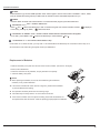
Change for Life
Service Manual
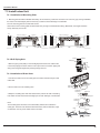
02'(/6*:+1$.11%&
*:+1$.11$&
*:+1%.11%&
*:+1%.11$&
*:+1%.11$&
5HIULJHUDQW5$
I
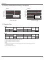
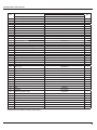
7DEOHRI&RQWHQWV
7DEOHRI&RQWHQWV
6XPPDU\DQG)HDWXUHV
6DIHW\3UHFDXWLRQV
6SHFL¿FDWLRQV
8QLW6SHFL¿FDWLRQV
&DSDFLW\9DULDWLRQ5DWLR$FFRUGLQJWR7HPSHUDWXUH
2SHUDWLRQ'DWD
&RQVWUXFWLRQ9LHZV
,QGRRU8QLW
2XWGRRU8QLW
5HIULJHUDQW6\VWHP'LDJUDP
6FKHPDWLF'LDJUDP
(OHFWULFDO:LULQJ
3ULQWHG&LUFXLW%RDUG
)XQFWLRQDQG&RQWURO
5HPRWH&RQWURO2SHUDWLRQV
'HVFULSWLRQRI(DFK&RQWURO2SHUDWLRQ
,QVWDOODWLRQ0DQXDO
1RWLFHVIRULQVWDOODWLRQ
,QVWDOODWLRQ'UDZLQJ
,QVWDOO,QGRRU8QLW
,QVWDOO2XWGRRU8QLW
&KHFNDIWHU,QVWDOODWLRQDQG2SHUDWLRQ7HVW
,QVWDOODWLRQDQG0DLQWHQDQFHRI+HDOWK\)LOWHU
([SORGHG9LHZVDQG3DUWV/LVW
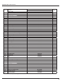
7DEOHRI&RQWHQWV
,QGRRU8QLW
2XWGRRU8QLW
7URXEOHVKRRWLQJ
3UHFDXWLRQVEHIRUH3HUIRUPLQJ,QVSHFWLRQRU5HSDLU &RQ¿UPDWLRQ
-XGJHPHQWE\)ODVKLQJ/('RI,QGRRU2XWGRRU8QLW +RZWR&KHFN6LPSO\WKH0DLQ3DUW
5HPRYDO3URFHGXUH
5HPRYDO3URFHGXUHRI,QGRRU8QLW
5HPRYDO3URFHGXUHRI2XWGRRU8QLW
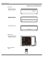
6XPPDU\DQG)HDWXUHV
6XPPDU\DQG)HDWXUHV
,QGRRU8QLW
*:+1$.11%&,
*:+1%.11%&,
*:+1$.11$&,
*:+1%.11$&,
*:+1%.11$&,
2XWGRRU8QLW
*:+1$.11%&2
*:+1%.11%&2
5HPRWH&RQWUROOHU
<;)
T-ON T-OFF
AUTO
COOL
DRY
FAN
HEAT
SWING
SLEEP
LOCK
SPEED
ON/OFF
MODE
-
+
FAN
SWING
SLEEP
TIMER
6DIHW\3UHFDXWLRQV
6DIHW\3UHFDXWLRQV
Installing, starting up, and servicing air conditioner can be
hazardous due to system pressure, electrical components,
and equipment location, etc.
Only trained, qualified installers and service personnel are
allowed to install, start-up, and service this equipment.
Untrained personnel can perform basic maintenance functions such as cleaning coils. All other operations should
be performed by trained service personnel.
Make sure the outdoor unit is installed on a stable, level
surface with no accumulation of snow, leaves, or trash
beside.
When handling the equipment, observe precautions in the
manual and on tags, stickers, and labels attached to the
equipment. Follow all safety codes. Wear safety glasses
andwork gloves. Keep quenching cloth and fire extinguisher
nearby when brazing.
Follow all the installation instructions to minimize the risk
of damage from earthquakes, typhoons or strong winds.
Read the instructions thoroughly and follow all warnings or
cautions in literature and attached to the unit. Consult local
building codes and current editions of national as well as
local electrical codes.
Recognize the following safety information:
Warning
Incorrect handling could result in
personal injury or death.
Caution
Incorrect handling may result in
minor injury,or damage to product
or property.
Warning
All electric work must be performed by a licensed technician
according to local regulations and the instructions given in
this manual.
Before installing, modifying, or servicing system, main
electrical disconnect switch must be in the OFF position.
There may be more than 1 disconnect switch. Lock out
and tag switch with a suitable warning label.
Never supply power to the unit unless all wiring and tubing are completed, reconnected and checked.
This system adopts highly dangerous electrical voltage.
Incorrect connection or inadequate grounding can cause
personal injury or death. Stick to the wiring diagram and
all the instructions when wiring.
Have the unit adequately grounded in accordance with
local electrical codes.
Have all wiring connected tightly. Loose connection may
lead to overheating and a possible fire hazard.
All installation or repair work shall be performed by your dealer or a specialized subcontractor as there is the risk of fire,
electric shock, explosion or injury.
Make sure the ceiling/wall is strong enough to bear the
weight of the unit.
Make sure the noise of the outdoor unit does not disturb
neighbors.
Avoid contact between refrigerant and fire as it generates
poisonous gas.
Apply specified refrigerant only. Never have it mixed with
any other refrigerant. Never have air remain in the
refrigerant line as it may lead to rupture and other hazards.
Make sure no refrigerant gas is leaking out when installation is completed.
Should there be refrigerant leakage, the density of refrigerant in the air shall in no way exceed its limited value,
or it may lead to explosion.
Keep your fingers and clothing away from any moving
parts.
Clear the site after installation. Make sure no foreign objects are left in the unit.
Always ensure effective grounding for the unit.
Caution
Never install the unit in a place where a combustible gas
might leak, or it may lead to fire or explosion.
Make a proper provision against noise when the unit is
installed at a telecommunication center or hospital.
Provide an electric leak breaker when it is installed in a
watery place.
Never wash the unit with water.
Handle unit transportation with care. The unit should not
be carried by only one person if it is more than 20kg.
Never touch the heat exchanger fins with bare hands.
Never touch the compressor or refrigerant piping without
wearing glove.
Do not have the unit operate without air filter.
Should any emergency occur, stop the unit and disconnect the power immediately.
Properly insulate any tubing running inside the room to
prevent the water from damaging the wall.
6SHFL¿FDWLRQV
6SHFL¿FDWLRQV
8QLW6SHFL¿FDWLRQV
9̚
*:+1$.11%&
*:+1$.11$&
&$
&$
+]
0RGHO
3URGXFW&RGH
5DWHG9ROWDJH
3RZHU
5DWHG)UHTXHQF\
6XSSO\
3KDVHV
3RZHU6XSSO\0RGH
,QGRRU
&RROLQJ&DSDFLW\
:
+HDWLQJ&DSDFLW\
:
&RROLQJ3RZHU,QSXW
:
+HDWLQJ3RZHU,QSXW
:
&RROLQJ3RZHU&XUUHQW
$
+HDWLQJ3RZHU&XUUHQW
$
5DWHG,QSXW
:
5DWHG&XUUHQW
$LU)ORZ9ROXPH6++0/6/
'HKXPLGLI\LQJ9ROXPH
$
PK
/K
((5
::
&23
::
6((5
::
+63)
::
P
$SSOLFDWLRQ$UHD
*:+1$.11%&,
*:+1$.11$&,
0RGHORILQGRRUXQLW
)DQ7\SH
&URVVÀRZ
'LDPHWHU/HQJWK';/
PP
ĭ;
)DQ0RWRU&RROLQJ6SHHG6++0/6/
UPLQ
)DQ0RWRU+HDWLQJ6SHHG6++0/6/ UPLQ
2XWSXWRI)DQ0RWRU
:
)DQ0RWRU5/$
$
)DQ0RWRU&DSDFLWRU
ȝ)
,QSXWRI+HDWHU
:
(YDSRUDWRU)RUP
,QGRRU
8QLW 3LSH'LDPHWHU
5RZ¿Q*DS
&RLO/HQJWK/;';:
PP
ĭ
PP
PP
;;
6ZLQJ0RWRU0RGHO
$OXPLQXP)LQFRSSHU7XEH
03$$
2XWSXWRI6ZLQJ0RWRU
:
)XVH
$
6RXQG3UHVVXUH/HYHO6++0/6/
G%$
6RXQG3RZHU/HYHO6++0/6/
G%$
'LPHQVLRQ:;+;'
PP
;;
'LPHQVLRQRI&DUWRQ%R[/;:;+
PP
;;
'LPHQVLRQRI3DFNDJH/;:;+
PP
;;
1HW:HLJKW
NJ
*URVV:HLJKW
NJ
6SHFL¿FDWLRQV
0RGHORI2XWGRRU8QLW
*:+1$.11%&2
&RPSUHVVRU0DQXIDFWXUHU7UDGHPDUN
=+8+$,/$1'$&2035(6625&2/7'*5((
&RPSUHVVRU0RGHO
4;$%&
&RPSUHVVRU2LO
32(=H*/(65%(3
&RPSUHVVRU7\SH
5RWDU\
/5$
$
&RPSUHVVRU5/$
$
&RPSUHVVRU3RZHU,QSXW
:
2YHUORDG3URWHFWRU
,QWHUQDO83
7KURWWOLQJ0HWKRG
2SHUDWLRQ7HPS
&DSLOODU\
ć
̚ $PELHQW7HPS&RROLQJ
ć
̚ $PELHQW7HPS+HDWLQJ
ć
̚ &RQGHQVHU)RUP
$OXPLQXP)LQFRSSHU7XEH
3LSH'LDPHWHU
PP
5RZV¿Q*DS
PP
&RLO/HQJWK/;';:
PP
;;
)DQ0RWRU6SHHG
USP
:
$
ȝ)
2XWSXWRI)DQ0RWRU
2XWGRRU )DQ0RWRU5/$
8QLW )DQ0RWRU&DSDFLWRU
$LU)ORZ9ROXPHRI2XWGRRU8QLW
ĭ
P K
)DQ7\SH
)DQ'LDPHWHU
$[LDOÀRZ
PP
'HIURVWLQJ0HWKRG
ĭ
$XWRPDWLF'HIURVWLQJ
&OLPDWH7\SH
7
,VRODWLRQ
,
0RLVWXUH3URWHFWLRQ
,3
3HUPLVVLEOH([FHVVLYH2SHUDWLQJ3UHVVXUH
IRUWKH'LVFKDUJH6LGH
03D
3HUPLVVLEOH([FHVVLYH2SHUDWLQJ
3UHVVXUHIRUWKH6XFWLRQ6LGH
03D
6RXQG3UHVVXUH/HYHO+0/
G%$
6RXQG3RZHU/HYHO+0/
G%$
'LPHQVLRQ:;+;'
PP
;;
'LPHQVLRQRI&DUWRQ%R[/;:;+
PP
;;
'LPHQVLRQRI3DFNDJH/;:;+
PP
;;
1HW:HLJKW
NJ
*URVV:HLJKW
NJ
5HIULJHUDQW
5HIULJHUDQW&KDUJH
NJ
/HQJWK
P
*DV$GGLWLRQDO&KDUJH
&RQQHFWLRQ2XWHU'LDPHWHU/LTXLG3LSH
3LSH
2XWHU'LDPHWHU*DV3LSH
JP
PP
ĭ
PP
ĭ
0D['LVWDQFH+HLJKW
P
0D['LVWDQFH/HQJWK
P
7KHDERYHGDWDLVVXEMHFWWRFKDQJHZLWKRXWQRWLFH3OHDVHUHIHUWRWKHQDPHSODWHRIWKHXQLW
5$
6SHFL¿FDWLRQV
*:+1%.11%&
*:+1%.11$&
*:+1%.11$&
0RGHO
&$
&$
&$
3URGXFW&RGH
5DWHG9ROWDJH
3RZHU
5DWHG)UHTXHQF\
6XSSO\
3KDVHV
9̚
+]
3RZHU6XSSO\0RGH
,QGRRU
&RROLQJ&DSDFLW\
:
+HDWLQJ&DSDFLW\
:
&RROLQJ3RZHU,QSXW
:
+HDWLQJ3RZHU,QSXW
:
&RROLQJ3RZHU&XUUHQW
$
+HDWLQJ3RZHU&XUUHQW
$
5DWHG,QSXW
:
5DWHG&XUUHQW
$LU)ORZ9ROXPH6++0/6/
'HKXPLGLI\LQJ9ROXPH
$
PK
/K
((5
::
&23
::
6((5
::
+63)
::
P
$SSOLFDWLRQ$UHD
*:+1%.11%&,
*:+1%.11$&,
*:+1%.11$&,
0RGHORILQGRRUXQLW
)DQ7\SH
'LDPHWHU/HQJWK';/
&URVVÀRZ
PP
ĭ;
)DQ0RWRU&RROLQJ6SHHG6++0/6/ UPLQ
)DQ0RWRU+HDWLQJ6SHHG6++0/6/ UPLQ
2XWSXWRI)DQ0RWRU
:
)DQ0RWRU5/$
$
)DQ0RWRU&DSDFLWRU
ȝ)
,QSXWRI+HDWHU
,QGRRU (YDSRUDWRU)RUP
8QLW
3LSH'LDPHWHU
:
$OXPLQXP)LQFRSSHU7XEH
PP
ĭ
5RZ¿Q*DS
PP
&RLO/HQJWK/;';:
PP
;;
6ZLQJ0RWRU0RGHO
03$$
2XWSXWRI6ZLQJ0RWRU
:
)XVH
$
6RXQG3UHVVXUH/HYHO6++0/6/
G%$
6RXQG3RZHU/HYHO6++0/6/
G%$
'LPHQVLRQ:;+;'
PP
;;
'LPHQVLRQRI&DUWRQ%R[/;:;+
PP
;;
'LPHQVLRQRI3DFNDJH/;:;+
PP
;;
1HW:HLJKW
NJ
*URVV:HLJKW
NJ
6SHFL¿FDWLRQV
0RGHORI2XWGRRU8QLW
*:+1%.11%&2
&RPSUHVVRU0DQXIDFWXUHU7UDGHPDUN
=+8+$,/$1'$&2035(6625&2/7'*5((
&RPSUHVVRU0RGHO
4;$%&
&RPSUHVVRU2LO
5%(3
&RPSUHVVRU7\SH
5RWDU\
/5$
$
&RPSUHVVRU5/$
$
&RPSUHVVRU3RZHU,QSXW
:
2YHUORDG3URWHFWRU
,QWHUQDO
7KURWWOLQJ0HWKRG
&DSLOODU\
2SHUDWLRQ7HPS
ć
̚ $PELHQW7HPS&RROLQJ
ć
̚ $PELHQW7HPS+HDWLQJ
ć
̚ &RQGHQVHU)RUP
$OXPLQXP)LQFRSSHU7XEH
3LSH'LDPHWHU
PP
5RZV¿Q*DS
PP
&RLO/HQJWK/;';:
PP
;;
)DQ0RWRU6SHHG
USP
:
$
ȝ)
2XWSXWRI)DQ0RWRU
2XWGRRU )DQ0RWRU5/$
)DQ0RWRU&DSDFLWRU
8QLW
$LU)ORZ9ROXPHRI2XWGRRU8QLW
ĭ
P K
)DQ7\SH
)DQ'LDPHWHU
$[LDOÀRZ
PP
'HIURVWLQJ0HWKRG
ĭ
$XWRPDWLF'HIURVWLQJ
&OLPDWH7\SH
7
,VRODWLRQ
,
0RLVWXUH3URWHFWLRQ
3HUPLVVLEOH([FHVVLYH2SHUDWLQJ3UHVVXUH
IRUWKH'LVFKDUJH6LGH
3HUPLVVLEOH([FHVVLYH2SHUDWLQJ3UHVVXUH
IRUWKH6XFWLRQ6LGH
,3
03D
03D
6RXQG3UHVVXUH/HYHO+0/
G%$
6RXQG3RZHU/HYHO+0/
G%$
'LPHQVLRQ:;+;'
PP
;;
'LPHQVLRQRI&DUWRQ%R[/;:;+
PP
;;
'LPHQVLRQRI3DFNDJH/;:;+
PP
;;
1HW:HLJKW
NJ
*URVV:HLJKW
NJ
5HIULJHUDQW
5$
5HIULJHUDQW&KDUJH
NJ
/HQJWK
P
JP
*DV$GGLWLRQDO&KDUJH
&RQQHFWLRQ2XWHU'LDPHWHU/LTXLG3LSH
3LSH
2XWHU'LDPHWHU*DV3LSH
PP
ĭ
PP
ĭ
0D['LVWDQFH+HLJKW
P
0D['LVWDQFH/HQJWK
P
7KHDERYHGDWDLVVXEMHFWWRFKDQJHZLWKRXWQRWLFH3OHDVHUHIHUWRWKHQDPHSODWHRIWKHXQLW
6SHFL¿FDWLRQV
&DSDFLW\9DULDWLRQ5DWLR$FFRUGLQJWR7HPSHUDWXUH
Cooling
Heating
Capacity ratio(%)
100
90
80
Condition
Indoor:DB27℃ WB19℃
Indoor air flow: Super High
Pipe length:5m
70
60
50
Capacity ratio(%)
120
110
100
80
60
Condition
Indoor:DB20℃
Indoor air flow:
Super High
Pipe length:5m
40
20
40
32 33 34 35 36 37 38 39 40 41 42 43 44 45
Outdoor temp.(
0
)
-15 -13-11 -9 -7 -5 -3 -1 1 3
Outdoor temp.(
5
7 9 11
)
2SHUDWLRQ'DWD
&RROLQJ
7HPSHUDWXUHFRQGLWLRQ&
,QGRRU
2XWGRRU
0RGHO
QDPH
.
.
6WDQGDUGSUHVVXUH +HDWH[FKDQJHUSLSHWHPS ,QGRRUIDQ 2XWGRRUIDQ
303D
a
7&
LQa
7&
LQa
RXWa
RXWa
PRGH
PRGHUSP
6XSHU+LJK
+HDWLQJ
7HPSHUDWXUHFRQGLWLRQ&
,QGRRU
2XWGRRU
0RGHO
QDPH
.
.
6WDQGDUGSUHVVXUH +HDWH[FKDQJHUSLSHWHPS ,QGRRUIDQ 2XWGRRUIDQ
303D
a
7&
LQa
7&
LQa
RXWa
RXWa
PRGH
PRGHUSP
6XSHU+LJK
33UHVVXUHRIDLUSLSHFRQQHFWLQJLQGRRUDQGRXWGRRUXQLWV
7,QOHWDQGRXWOHWSLSHWHPSHUDWXUHRIHYDSRUDWRU
7,QOHWDQGRXWOHWSLSHWHPSHUDWXUHRIFRQGHQVHU
127(6
0HDVXUHVXUIDFHWHPSHUDWXUHRIKHDWH[FKDQJHUSLSHDURXQGFHQWHURIKHDWH[FKDQJHUSDWK8EHQW
7KHUPLVWRUWKHPRPHWHU
&RQQHFWLQJSLSLQJFRQGLWLRQP
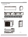
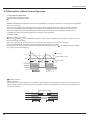
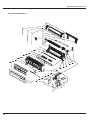
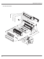
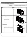
&RQVWUXFWLRQ9LHZV
&RQVWUXFWLRQ9LHZV
,QGRRU8QLW
D
H
W
L1
L
L2
L1
L
12k
L2
09k
Model
W
H
D
L
L1
L2
12K
790
265
177
605
35
150
09K
730
255
174
562
27
141
8QLWPP
2XWGRRU8QLW
257
540
776
714
320
286
510
8QLWPP
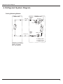
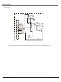
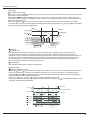
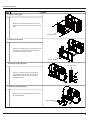
5HIULJHUDQW6\VWHP'LDJUDP
5HIULJHUDQW6\VWHP'LDJUDP
&RROLQJ+HDWLQJ0RGHOV
Wide tube
Wide tube
service
valve
Outdoor unit
Accumlator
Compressor
Indoor unit
Narrow
tube
service
valve
Capillary tube
Narrow tube
Strainer
Heat exchanger
Heat exchanger
4-way valve
Strainer Capillary tube
Cooling
cycle
Heating
cycle
5HIULJHUDQWSLSHGLDPHWHU
/LTXLGPP
*DVPP
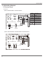
6FKHPDWLF'LDJUDP
6FKHPDWLF'LDJUDP
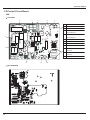
(OHFWULFDO:LULQJ
,QGRRU8QLW
0RGHOV*:+1$.11%&,*:+1$.11$&,
DISPLAY
ROOM
0
0
RT2
RT1
BN(BK)
BU(WH)
YEGN(GN)
AP1
N1
ROOM
TUBE
XT1
W1BU
N
2
4
5
W2BK
W4VT
DISP1 DISP2
W5OG
AP2
CAP
AC-L
PRINTED CIRCUIT BOARD
JUMP
K1
OFAN
M2
VT
OG
YEGN
COMP
EVAPORATOR
FAN MOTOR
0RGHOV*:+1%.11%&,*:+1%.11$&,*:+1%.11$&,
ROOM
FAN MOTOR
DISPLAY
0
0
RT2
RT1
BN(BK)
BU(WH)
YEGN(GN)
M1
N1
ROOM
TUBE
XT1
W1BU
PG PGF
DISP1 DISP2
N
2
4
5
W2BK
W4VT
W5OG
AP2
CAP
JUMP
AC-L
PRINTED CIRCUIT BOARD
SWING-UD
COMP
K1
4V
TR_OUT
TR_IN
EVAPORATOR
OFAN
M2
TC
STEPPING
MOTOR
I
II
TRANSFORMER
W3
YEGN
POWER
L
N
CONN WIRE
BU
BK
VT
OG
YEGN
OUTDOOR UNIT
PIPE
TEM.SENSOR TEM.SENSOR AP1
Color symbol
ORANGE
VIOLET
WHITE
YELLOW
RED
YELLOW GREEN
OVERLOAD
BROWN
BLUE
BLACK
Parts name
PROTECTIVE EARTH
M1
STEPPING
MOTOR
Symbol
OG
VT
WH
YE
RD
YEGN
SAT
BN
BU
BK
Symbol
4V
PGF PG
SWING-UD
CONN WIRE
BU
BK
W3
YEGN
COMP
L
N
OUTDOOR UNIT
PIPE
TEM.SENSOR TEM.SENSOR
POWER
COMPRESSOR
6FKHPDWLF'LDJUDP
2XWGRRU8QLW
COMPRESSOR
C(T,U)
COMP E
S(W,X)
YEGN
R(M,V)
PE
BK
YE
C1
FAN MOTOR
BU(BK)
YEGN
INDOOR UNIT
BU
M
E
YEGN
PE
XT1
BU
BK
PE
BU
BN
N(1)
2
VT
4
OG
5
RD
C2
TERMINAL BLOCK
4YV
OG
7KHVHFLUFXLWGLDJUDPVDUHVXEMHFWWRFKDQJHZLWKRXWQRWLFHSOHDVHUHIHUWRWKHRQHVXSSOLHGZLWKWKHXQLW
6FKHPDWLF'LDJUDP
3ULQWHG&LUFXLW%RDUG
.
TOP VIEW
3
4
5
6
7
8
1
Compressor control relay K1
2
Protective tube
3
PG motor control terminal
4
4-way valve control terminal &
control relay K115
5
2
Outdoor fan control terminal &
control relay K114
1
6
Auto button
7
Up & down swing control terminal
8
PG motor feedback terminal
9
Display control terminal
10
Tube temperature sensor
connector
9
11
Ambient temperature sensor
connector
12
12
BOTTOM VIEW
11
10
High frequency transformer T1
6FKHPDWLF'LDJUDP
.
TOP VIEW
3
4
5
6
7
8
9
1
Compressor control relay
2
Protective tube
3
Indoor fan controls terminal
4
Terminal of power neutral wire interface
5
4-way valve control terminal and relay K115
6
Outdoor fan control terminal and relay K114
7
Auto button
2
1
10
13
8
Up&down swing control terminal
9
Interface feedback from indoor fan
10
Display control terminal
11
Interface of pipe temperature sensor
12
Interface of ambient temperature sensor
13
Input interface TR-IN and output interface
TR-OUT of linear transformer
12
11
BOTTOM VIEW
)XQFWLRQDQG&RQWURO
)XQFWLRQDQG&RQWURO
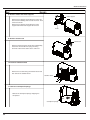
5HPRWH&RQWURO2SHUDWLRQV
1
ON/OFF
Press it to start or stop operation.
2
MODE
Press it to select operation mode(AUTO/COOL/DRY/FAN/HEAT).
1
2
3
4
5
6
7
8
3
- : Press it to decrease temperature setting.
4
+ : Press it to increase temperature setting.
5
FAN
Press it to set fan speed.
6
SWING
Press it set swing angle.
7
SLEEP
8
TIMER
Press it set auto-on/auto-off timer.
1 ON/OFF :
Press this button to start the unit operation .Press this button again to stop the unit operation.
2 MODE :
Each time you press the button,a mode is selected in a sequence that goes from AUTO,COOL,DRY, FAN,and HEAT*,
as the following:
AUTO
COOL
DRY
FAN
HEAT
*
*Note:Only for models with heating function.
3
-
:
Press this button to decrease set temperature.Holding it down above 2 seconds rapidly decreases set temperature. In
AUTO mode, set temperature is not adjustable.
4
+
:
Press this button to increase set temperature.Holding
it down above 2 seconds rapidly increases set temperature. In
.
AUTO mode, set temperature is not adjustable.
5 FAN:
This button is used for setting Fan Speed in the sequence that goes from AUTO,
to Auto.
Auto
Speed 1
Speed 2
6 SWING :
Press this key to activate or deactivate the swing.
Speed 3
Speed 4
,
,
to
,then back
)XQFWLRQDQG&RQWURO
7 SLEEP:
Press this button to go into the SLEEP operation mode. Press it again to cancel. This function is available in COOL , HEAT
(Only for models with heating function) or DRY mode to maintain the most comfortable temperature for you.
8 TIMER:
Press this button to initiate auto-on/auto-off timer. To cancel auto-timer program, press this button twice.
94 Combination of "+" and "-" buttons: About lock
Press " + " and " - " buttons simultaneously to lock or unlock the keypad. If the remote controller is locked ,
I n this case, press ing any button,
is displayed
blinks three times.
10 Combination of "MODE " and "-" buttons: About switch between fahrenheit and cenrigrade
At unit OFF , press "MODE " and " - " buttons simultaneously to switch between
11
and
.
Combination of "+" and "FAN" buttons:About Lamp
Under switch-on or switch-off state, you may hold "+" and "FAN" buttons simultaneously for 3 seconds to set the lamp on or
off and send the code. After being energized, the lamp is defaulted on.
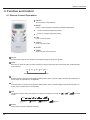
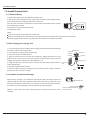
Replacement of Batteries
1.Remove the battery cover plate from the rear of the remote controller. (As shown in the figure)
2.Take out the old batteries.
3.Insert two new AAA1.5V dry batteries, and pay attention to the polarity.
4. Close the battery cover plate.
Notes:
●
When replacing the batteries, do not use old or different types of batteries
otherwise, it may cause malfunction.
●
Fig.1
If the remote controller will not be used for a long time, please remove batteries
to prevent batteries from leaking.
●
The operation should be performed in its receiving range.
●
●
It should be kept 1m away from the TV set or stereo sound sets.
If the remote controller does not operate normally, please take the batteries out
and replace them after 30 seconds. If still not operating properly.replace the batteries.
Fig.2
)XQFWLRQDQG&RQWURO
'HVFULSWLRQRI(DFK&RQWURO2SHUDWLRQ
1 Temperature Parameters
Indoor preset temperature (Tpreset)
Indoor ambient temperature (Tamb.)
2 Basic functions (The temperature in this manual is expressed by Centigrade. If Fahrenheit, is used, the switchover between
them is Tf=TcX1.8+32.)
Once the unit is energized, the compressor shall never be restarted except 3mins interval at least. For the first energization,
if the unit is at off status before power failure, the compressor can be restarted without 3-min delay. But if the unit is at on
status before power failure, the compressor shall be restarted with 3mins delay. Once the compressor is started up, the
compressor won't stop running within 6mins with the change of room temperature.
(1)Cooling mode
Cooling conditions and process
When Tamb. Tpreset+1 , the unit starts cooling operation. In this case, the compressor and the outdoor fan operate and the
indoor fan operates at set speed.
When Tamb. Tpreset-1 , the compressor and the outdoor fan stop while the indoor fan runs at set speed.
Tamb. Tpreset+1 , the unit will maintain its previous running state.
When Tpreset-1
In cooling mode, the four-way valve is de-energized; temperature setting range is 16 30
the indoor unit displays operation
icon, cooling icon and set temperature.
Start cooling
Tamb.
Tpreset+1
Original operating status
Tpreset 1
min.
min.
min.
Stop cooling
Compressor
Outdoor fan
Set Fan speed
Indoor fan
Stop
Run
Protection Functions
Freeze potection
If the system is under freeze protection, the compressor and the outdoor fan stop operation, and the indoor fan operates at set
speed. If freeze protection is eliminated and the compressor has been out of operation for 3 minutes, the unit will resume its
previous running state.
Freeze protection period
min
Compressor
Outdoor fan
Set Fan Speed
Indoor fan
Run
Stop
)XQFWLRQDQG&RQWURO
(2)Dry Mode
Dry Conditions and Process
When Tamb. Tpreset+2 , the unit will run in dry and cooling mode, in that case the compressor and outdoor fan will run and
the indoor fan will run at low speed.
Tamb. Tpreset+2 , the unit will run in dry mode, in that case, the indoor fan will run at low speed, the
When Tpreset-2
compressor and the outdoor fan will be stopped in 6 min. After 4 min, the compressor and the outdoor fan will be restarted. Dry
process is cycled as the above.
When Tamb. Tpreset-2 , the compressor and the outdoor fan will stop working and the indoor fan will run at low speed.
In this mode, the four-way valve is de-energized, and setting temperature range is between 16 30 . The displayer will display
running and drying icons and setting temperature.
Tamb.
Cooling
Tpreset+2
Dehumidfying
Tpreset 2
min
.
Stop
min.
min.
min.
Compressor
Outdoor fan
Indoor fan
Low speed
Run
Stop
Protection
Freeze potection
If freeze protection of the system is detected in dry and cooling mode, the compressor and the outdoor fan will stop
running and the indoor fan will run at low speed. When the freeze protection is released and the compressor has been
stopped for 3 min, the complete unit will resume its previous running state. Upon the condition that the compressor runs for 6
min and stops for 4 min is met and freeze protection is detected, the compressor and the outdoor fan will stop running and
the indoor fan will run at low speed. When the freeze protection is released and the compressor has been stopped for 4
min, the complete unit will resume its previous running state.
Other protection
Other protections are the same as those in cooling mode.
(3)Heating mode
Heating conditions and process
When Tamb. Tpreset+2 , the unit will run in heating mode, in that case, the four-way valve, the compressor and the outdoor
fan will run simultaneously. The indoor fan will delay at most 2mins to run. The indoor fan will run 2 mins delayed at most.
When Tamb Tpreset+4 , the compressor and the outdoor fan will stop and the four-way valve will remain energized(keep
energizing) and the indoor fan will blow residual heat.
T amb.
Tpreset +4 , the unit will maintain its previous running state.
When Tpreset +2
Under this mode, the four-way valve is energized, and setting temperature range is 16 30 . The displayer will display running
and heating icons and setting temperature.
stop heating
Tpreset
original operation status
Tpreset
Tamb.
start heating
min
min
min
Compressor
Outdoor unit
Indoor unit
min
setting
fan speed
min
setting
fan speed
4-way valve
Run
Stop
)XQFWLRQDQG&RQWURO
Defrosting Conditions and Process
The unit with intelligent defrosting function can defrost according to frosting conditions. Dual8 displays H1.
Protection Function
High Temp Resistance Protection
If it is detected that the evaporator tube temperature is superheating, the outdoor fan will stop working. When the tube temperature
resumes to normal condition, the outdoor fan will resume running.
Noise Silencing Protection
If the unit is stopped by pressing ON/OFF or during switchover of modes, the reversing valve will be stopped after 2 min.
(4)Fan mode
In this mode, indoor fan runs at setting speed, and the compressor, the outdoor fan, the four-way valve and the electric heating tube
will stop running.
In this mode, temperature setting range is 16 30 . Displayer displays running icons and the setting temperature.
(5)Auto Mode
In this mode, the air conditioner will automatically select its running mode (cooling, heating or fan) with the change of ambient
temperature. The displayer will display the running icons, actual running mode icon and setting temperature. There is 30s delay
protection for mode switching. Protection functions are the same as those in any other mode.
3 Other Control
(1)Timer function
The mainboard combines general timer and clock timer functions. Timer functions are selected by equipping remote controller with
different functions.
General Timer:
Timer ON can be set under off state of unit. If timer ON reaches, the controller will run under previous setting mode. Timing interval
is 0.5hr and the setting range is 0.5-24hr.
Timer OFF can be set under on state of unit. If timer OFF reaches, the unit is turned off. Timing interval is 0.5hr within the range of
0.5-24hr.
Clock Timer:
If timer on is set under running state of unit, the system will continue running. If timer on is set under off state of unit, the system will
run in presetting mode when timer on reaches.
If timer off is set under off state of unit, the system will keep standby state. If timer off is set under on state of unit, the system will
stop running when timer off reaches.
Timer Change:
If the system is under timer state, the unit can be turned on/off by ON/OFF button of remote controller. Timing can also be reset and
then the system runs according to the final setting.
If timer on and timer off is set at the same time under running state of system, the system will keep present running state till timer off
reaches and then it will stop running.
If timer on and timer off are set at the same time under off state of system, the system will keep stopping till timer on reaches and
then it will start running.
In the future, the system will run in presetting mode when timer on reaches and stop when timer off reaches every day. If timer on
and timer off have the same setting, timer off is prevails.
(2)Auto Button
If press this button, the system will run in auto mode, and the indoor fan motor will run at auto speed; meanwhile, the swing motor
will be running. Repress this button to turn off the unit.
(3)Buzzer
When the controller is energized or receives any command or signal from the buttons or the remote controller, the buzzer will give
out a beep.
(4)Sleep Function
Choose the sleeping curve according to the preset temperature.
(5)Turbo Function
This function can be set in cooling or heating mode.
)XQFWLRQDQG&RQWURO
(6)Dry Function
This function can be set in cooling or dry mode.
(7)Automatic Control of Fan Speed
In this mode, the indoor fan will automatically select high, medium or low speed with the change of ambient temperature.
(8)Up & Down Swing
After energization, up & down swing motor will rotate guide louver anticlockwise to position 0 to close air outlet.
After turning on the unit, if swing function has not been set, up & down guide louver will clockwise turn to position D in heating mode,
or clockwise turn to level position L in other modes.
If the unit is turned on with swing function setting, the guide louver will swing between W and D. There are 7 kinds of swing states of
guide louver: There are position L, A, B, C, D, and it swings and stops between L and D ( angle between L and D is equiangular).
Upon stop of unit, the guide louver will close to position O. Swing action is valid only when swing command is set and indoor fan is
running.
Note: If the position is set between L and B, A and C or B and D by remote controller, the guide louver will swing between L and D.
degree
(9)Display
Running icon and Mode icon
Upon energization, the unit will display all icons. Under standby state, running indicating icon is displayed in red. If the unit is started
by remote controller, running indicating icon gives off light; Meanwhile, the present setting running mode icon will be displayed(mode
LED: cooling, heating and dry mode). If the light button is turned off, all icons display will be closed.
Dual-8 Display
After starting the unit for the first time, the nixie tube will display present setting temperature in default (16-30 ) the nixie tube will
default to display the preset temperature. When displaying setting temperature signal is received, the nixie tube will display setting
temp. If displaying ambient temperature signal is received, the nixie tube will display present indoor ambient temperature. If other
states are set by remote controller, the display will keep previous. If remote controller receives valid signal during displaying ambient
temperature, ambient temperature will be displayed after setting temperature is displayed for 5s. F1 is displayed for ambient
temperature sensor malfunction, F2 for tube temp sensor malfunction of indoor unit and C5 for jumper cap has malfunction.
Some models: The remote controller will display present setting temp when this display is set. The controller will display ambient
temp for 5s and then setting temp only when indoor ambient temp displaying state is switched from other displaying states by
remote controller.
(10)Locked protection to PG motor
When starting the fan, if motor’s rotational speed is slow for a period of time, the unit will display Locked and stop running to avoid
auto protection for motor. If the unit is on currently, error code H6 will be displayed by the dual-8 nixie tube. If the unit is off currently,
this locked malfunction information won’t be displayed.
(11)Power-off memory
Memory content includes mode, up&down swing, light, setting temp and setting fan speed.
Upon power failure, the unit after power recovery will automatically start to run according to memory content. The system, last
remote-control command without timer setting, will memorize the last remote-control signal and run according to it. If the last remote
controller command has general timer function and the system is de-energized before setting time, the system will memorize the last
timer function in remote controller command after re-energization and time will be recalculated. If there is function in the last remote
controller command but setting time has reached, the system will act as timer on/off setting before de-energization. After
re-energization, the system memorizes the running states before power failure without timer action.
Clock timer can not be memorized.
,QVWDOODWLRQ0DQXDO
,QVWDOODWLRQ0DQXDO
1RWLFHVIRULQVWDOODWLRQ
&DXWLRQ
7KH XQLW VKRXOG EH LQVWDOOHG RQO\ E\ DXWKRUL]HG VHUYLFH FHQWHU DFFRUGLQJ WR ORFDO RU JRYHUQPHQW UHJXODWLRQV DQG LQ
FRPSOLDQFHZLWKWKLVPDQXDO
%HIRUHLQVWDOOLQJSOHDVHFRQWDFWZLWKORFDODXWKRUL]HGPDLQWHQDQFHFHQWHU,IWKHXQLWLVQRWLQVWDOOHGE\WKHDXWKRUL]HG
VHUYLFHFHQWHUWKHPDOIXQFWLRQPD\QRWEHVROYHGGXHWRLQFRYHQLHQWFRQWDFWEHWZHHQWKHXVHUDQGWKHVHUYLFHSHUVRQQHO
:KHQUHPRYLQJWKHXQLWWRWKHRWKHUSODFHSOHDVH¿UVWO\FRQWDFWZLWKWKHORFDODXWKRUL]HGVHUYLFHFHQWHU
:DUQLQJ%HIRUHREWDLQLQJDFFHVVWRWHUPLQDOVDOOVXSSO\FLUFXLWVPXVWEHGLVFRQQHFWHG
)RUDSSOLDQFHVZLWKW\SH<DWWDFKPHQWWKHLQVWUXFWLRQVVKDOOFRQWDLQWKHVXEVWDQFHRIWKHIROORZLQJ,IWKHVXSSO\FRUG
LVGDPDJHGLWPXVWEHUHSODFHGE\WKHPDQXIDFWXUHULWVVHUYLFHDJHQWRUVLPLODUO\TXDOL¿HGSHUVRQVLQRUGHUWRDYRLGD
KD]DUG
7KHDSSOLDQFHPXVWEHSRVLWLRQHGVRWKDWWKHSOXJLVDFFHVVLEOH
7KHWHPSHUDWXUHRIUHIULJHUDQWOLQHZLOOEHKLJKSOHDVHNHHSWKHLQWHUFRQQHFWLRQFDEOHDZD\IURPWKHFRSSHUWXEH
7KHLQVWUXFWLRQVVKDOOVWDWHWKHVXEVWDQFHRIWKHIROORZLQJ7KLVDSSOLDQFHLVQRWLQWHQGHGIRUXVHE\SHUVRQVLQFOXGLQJ
FKLOGUHQZLWKUHGXFHGSK\VLFDOVHQVRU\RUPHQWDOFDSDELOLWLHVRUODFNRIH[SHULHQFHDQGNQRZOHGJHXQOHVVWKH\KDYH
EHHQJLYHQVXSHUYLVLRQRULQVWUXFWLRQFRQFHUQLQJXVHRIWKHDSSOLDQFHE\DSHUVRQUHVSRQVLEOHIRUWKHLUVDIHW\&KLOGUHQ
VKRXOGEHVXSHUYLVHGWRHQVXUHWKDWWKH\GRQRWSOD\ZLWKWKHDSSOLDQFH
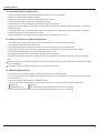
,QVWDOODWLRQ6LWH,QVWUXFWLRQV
3URSHULQVWDOODWLRQVLWHLVYLWDOIRUFRUUHFWDQGHI¿FLHQWRSHUDWLRQRIWKHXQLW$YRLGWKHIROORZLQJVLWHVZKHUH
VWURQJKHDWVRXUFHVYDSRXUVÀDPPDEOHJDVRUYRODWLOHOLTXLGVDUHHPLWWHG
KLJKIUHTXHQF\HOHFWURPDJQHWLFZDYHVDUHJHQHUDWHGE\UDGLRHTXLSPHQWZHOGHUVDQGPHGLFDOHTXLSPHQW
VDOWODGHQDLUSUHYDLOVVXFKDVFORVHWRFRDVWDODUHDV
WKHDLULVFRQWDPLQDWHGZLWKLQGXVWULDOYDSRXUVDQGRLOV
WKHDLUFRQWDLQVVXOSKXUHVJDVVXFKDVLQKRWVSULQJ]RQHV
FRUURVLRQRUSRRUDLUTXDOLW\H[LVWV
,QVWDOODWLRQ6LWHRI,QGRRU8QLW
7KHDLULQOHWDQGRXWOHWVKRXOGEHDZD\IURPWKHREVWUXFWLRQV(QVXUHWKHDLUFDQEHEORZQWKURXJKWKHZKROHURRP
6HOHFWDVLWHZKHUHWKHFRQGHQVDWHFDQEHHDVLO\GUDLQHGRXWDQGZKHUHLWLVHDVLO\FRQQHFWHGWRRXWGRRUXQLW
6HOHFWDSODFHZKHUHLWLVRXWRIUHDFKRIFKLOGUHQ
6HOHFWDSODFHZKHUHWKHZDOOLVVWURQJHQRXJKWRZLWKVWDQGWKHIXOOZHLJKWDQGYLEUDWLRQRIWKHXQLW
%HVXUHWROHDYHHQRXJKVSDFHWRDOORZDFFHVVIRUURXWLQHPDLQWHQDQFH7KHLQVWDOODWLRQVLWHVKRXOGEHFPRUPRUH
DERYHWKHÀRRU
6HOHFWDSODFHDERXWPRUPRUHDZD\IURP79VHWRUDQ\RWKHUHOHFWULFDSSOLDQFH
6HOHFWDSODFHZKHUHWKH¿OWHUFDQEHHDVLO\WDNHQRXW
0DNHVXUHWKDWWKHLQGRRUXQLWLVLQVWDOOHGLQDFFRUGDQFHZLWKLQVWDOODWLRQGLPHQVLRQLQVWUXFWLRQV
'RQRWXVHWKHXQLWLQWKHODXQGU\RUE\VZLPPLQJSRROHWF
,QVWDOODWLRQ0DQXDO
,QVWDOODWLRQ6LWHRI2XWGRRU8QLW
6HOHFWDVLWHZKHUHQRLVHDQGRXWÀRZDLUHPLWWHGE\WKHXQLWZLOOQRWDQQR\QHLJKERUV
6HOHFWDVLWHZKHUHWKHUHLVVXI¿FLHQWYHQWLODWLRQ
6HOHFWDVLWHZKHUHWKHUHLVQRREVWUXFWLRQEORFNLQJWKHLQOHWDQGRXWOHW
7KHVLWHVKRXOGEHDEOHWRZLWKVWDQGWKHIXOOZHLJKWDQGYLEUDWLRQ
6HOHFWDGU\SODFHEXWGRQRWH[SRVHXQGHUWKHGLUHFWVXQOLJKWRUVWURQJZLQG
0DNH VXUH WKDW WKH RXWGRRU XQLW LQVWDOODWLRQ GLPHQVLRQ VKRXOG DFFRUG ZLWK LQVWDOODWLRQ GLPHQVLRQ GLDJUDP FRQYHQLHQW IRU
PDLQWHQDQFHUHSDLU
7KHKHLJKWGLIIHUHQFHRIFRQQHFWLQJWKHWXELQJZLWKLQPWKHOHQJWKRIFRQQHFWLQJWKHWXELQJZLWKLQNPRUNP
6HOHFWDSODFHZKHUHLWLVRXWRIUHDFKIRUWKHFKLOGUHQ
6HOHFWDSODFHZKHUHWKHXQLWGRHVQRWKDYHQHJDWLYHLPSDFWRQSHGHVWULDQVRURQWKHFLW\
6DIHW\3UHFDXWLRQVIRU(OHFWULF$SSOLDQFHV
$GHGLFDWHGSRZHUVXSSO\FLUFXLWVKRXOGEHXVHGLQDFFRUGDQFHZLWKORFDOHOHFWULFDOVDIHW\UHJXODWLRQV
'RQ¶WGUDJWKHSRZHUFRUGZLWKH[FHVVLYHIRUFH
7KHXQLWVKRXOGEHUHOLDEO\HDUWKHGDQGFRQQHFWHGWRDQH[FOXVLYHHDUWKGHYLFHE\WKHSURIHVVLRQDOV
7KHDLUVZLWFKPXVWKDYHWKHIXQFWLRQVRIPDJQHWLFWULSSLQJDQGKHDWWULSSLQJWRSUHYHQWVKRUWFLUFXLWDQGRYHUORDG
7KHPLQLPXPGLVWDQFHEHWZHHQWKHXQLWDQGFRPEXVWLYHVXUIDFHLVP
7KHDSSOLDQFHVKDOOEHLQVWDOOHGLQDFFRUGDQFHZLWKQDWLRQDOZLULQJUHJXODWLRQV
$QDOOSROHGLVFRQQHFWLRQVZLWFKZLWKDFRQWDFWVHSDUDWLRQRIDWOHDVWPPLQDOOSROHVVKRXOGEHFRQQHFWHGLQ¿[HGZLULQJ
1RWH
0DNHVXUHWKHOLYHZLUHQHXWUDOZLUHDQGHDUWKZLUHLQWKHIDPLO\SRZHUVRFNHWDUHSURSHUO\FRQQHFWHG7KHUHVKRXOGEHUHOLDEOH
FLUFXLWLQWKHGLDJUDP
,QDGHTXDWHRULQFRUUHFWHOHFWULFDOFRQQHFWLRQVPD\FDXVHHOHFWULFVKRFNRU¿UH
(DUWKLQJ5HTXLUHPHQWV
$LUFRQGLWLRQHULVW\SH,HOHFWULFDSSOLDQFH3OHDVHHQVXUHWKDWWKHXQLWLVUHOLDEO\HDUWKHG
7KH\HOORZJUHHQZLUHLQDLUFRQGLWLRQHULVWKHHDUWKLQJZLUHZKLFKFDQQRWEHXVHGIRURWKHUSXUSRVHV,PSURSHUHDUWKLQJPD\
FDXVHHOHFWULFVKRFN
7KHHDUWKUHVLVWDQFHVKRXOGDFFRUGWRWKH1DWLRQDO&ULWHULRQ
7KHXVHUSRZHUPXVWRIIHUWKHUHOLDEOHHDUWKLQJWHUPLQDO3OHDVHGRQ¶WFRQQHFWWKHHDUWKLQJZLUHZLWKWKHIROORZLQJ
:DWHUSLSH*DVSLSH
&RQWDPLQDWLRQSLSH2WKHUSODFHVWKDWSURIHVVLRQDOSHUVRQQHOFRQVLGHUWKHPXQUHOLDEOH
7KHPRGHODQGUDWHGYDOXHVRIIXVHVVKRXOGDFFRUGZLWKWKHVLONSULQWRQIXVHFRYHURUUHODWHG3&%
,QVWDOODWLRQ0DQXDO
,QVWDOODWLRQ'UDZLQJ
Space to the ceiling
15cm
Above
Space to the wall
15cm Above
15cm Above
Space to the wall
250
cm
Above
300cm
Above
Air outlet side
Space to the floor
dimensions of the space necessary for proper
installation of the unit include the minimum
permissible distances to adjacent parts.
Space to the obstruction
50cm Above
ƽ The
Air inlet side
e
ov
cm
Ab
30
30cm Above
Space to the wall
Space to the wall
50cm Above
0
20
cm
A
v
bo
e
Air outlet side
Schematic diagram being reference only (outdoor unit is with variation),
please refer to real product for authentic information.
,QVWDOODWLRQ0DQXDO
,QVWDOO,QGRRU8QLW
,QVWDOODWLRQRI0RXQWLQJ3ODWH
0RXQWLQJSODWHVKRXOGEHLQVWDOOHGKRUL]RQWDOO\$VWKHZDWHUWUD\¶VRXWOHWIRUWKHLQGRRUXQLWLVWZRZD\W\SHGXULQJLQVWDOODWLRQ
WKHLQGRRUXQLWVKRXOGVOLJKWO\VODQWWRZDWHUWUD\¶VRXWOHWIRUVPRRWKGUDLQDJHRIFRQGHQVDWH
)L[WKHPRXQWLQJSODWHRQWKHZDOOZLWKVFUHZV
%HVXUHWKDWWKHPRXQWLQJSODWHKDVEHHQ¿[HG¿UPO\HQRXJKWRZLWKVWDQGDERXWNJ0HDQZKLOHWKHZHLJKWVKRXOGEH
HYHQO\VKDUHGE\HDFKVFUHZ
Wall
Wall
Mark on the middle of it
Space
to the
wall
1 5 0 mm
above
Left
Ф55
Gradienter
Space
to the
wall
1 5 0 mm
above
Right
(Rear piping hole)
12k
(Rear piping hole)
Ф55
Wall
Wall
Mark on the middle of it
Space
to the
wall
1 5 0 mm
above
Left
Ф55
Gradienter
Space
to the
wall
1 5 0 mm
above
Right
(Rear piping hole)
'ULOO3LSLQJ+ROH
09k
Ф55
(Rear piping hole)
Indoor
Outdoor
Wall pipe
Seal pad
6ODQWWKHSLSLQJKROHĭRQWKHZDOOVOLJKWO\GRZQZDUGWRWKHRXWGRRUVLGH
,QVHUWWKHSLSLQJKROHVOHHYHLQWRWKHKROHWRSUHYHQWWKHFRQQHFWLRQSLSLQJDQG
Φ55
ZLULQJIURPEHLQJGDPDJHGZKHQSDVVLQJWKURXJKWKHKROH
,QVWDOODWLRQRI'UDLQ+RVH
&RQQHFWWKHGUDLQKRVHWRWKHRXWOHWSLSHRIWKHLQGRRUXQLW%LQGWKHMRLQWZLWK
UXEEHUEHOW
3XWWKHGUDLQKRVHLQWRLQVXODWLQJWXEH
outlet pipe of
indoor unit
rubber belt
outlet pipe of
indoor unit
drain hose
outlet pipe of
indoor unit
drain hose
:UDSWKHLQVXODWLQJWXEHZLWKZLGHUXEEHUEHOWWRSUHYHQWWKHVKLIWRILQVXODWLQJ
WXEH6ODQWWKHGUDLQKRVHGRZQZDUGVOLJKWO\IRUVPRRWKGUDLQDJHRIFRQGHQVDWH
rubber belt insulating tube
rubber belt
outlet pipe of
indoor unit
1RWH
7KHLQVXODWLQJWXEHVKRXOGEHFRQQHFWHGUHOLDEO\ZLWKWKHVOHYHRXWVLGHWKH
RXWOHWSLSH7KHGUDLQKRVHVKRXOGEHGRZQZDUGVODQWZLWKRXWGLVWRUWLRQEXOJH
RUÀXFWXDWLRQ'RQRWSXWWKHZDWHURXWOHWLQWKHZDWHU
connected
bulge
insulating tube
distortion
Flooded
,QVWDOODWLRQ0DQXDO
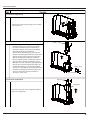
&RQQHFWLQJ,QGRRUDQG2XWGRRU(OHFWULF:LUHV
2SHQWKHIURQWSDQHO
5HPRYHWKHZLULQJFRYHUFRQQHFWDQG¿[WKHSRZHUFRQQHFWLRQFRUGDQGVLJQDOFRQWUROZLUHWRWKHWHUPLQDOERDUGDVVKRZQLQ)LJ
0DNHWKHSRZHUFRQQHFWLRQFRUGDQGVLJQDOFRQWUROZLUHSDVVWKURXJKWKHKROHDWWKHEDFNRILQGRRUXQLW
5HLQVWDOOWKHFODPSDQGZLULQJFRYHU
5HFRYHUWKHIURQWSDQHO
Wiring Cover
N
2
4
5
blue black violet orange yellowgreen
Fig 2
outdoor unit connection
127(
$OOZLUHVEHWZHHQLQGRRUDQGRXWGRRUXQLWVPXVWEHFRQQHFWHGE\WKHTXDOL¿HGHOHFWULFFRQWUDFWRU
(OHFWULFZLUHVPXVWEHFRQQHFWHGFRUUHFWO\,PSURSHUFRQQHFWLRQPD\FDXVHPDOIXQFWLRQ
7LJKWHQWKHWHUPLQDOVFUHZVVHFXUHO\
$IWHUWLJKWHQLQJWKHVFUHZVVOLJKWO\SXOOWKHZLUHDQGFRQ¿UPZKHWKHULWLV¿UPRUQRW
0DNHVXUHWKDWWKHHOHFWULFFRQQHFWLRQVDUHHDUWKHGSURSHUO\WRSUHYHQWHOHFWULFVKRFN
0DNHVXUHWKDWDOOZLULQJFRQQHFWLRQVDUHVHFXUHDQGWKHFRYHUSODWHVDUHUHLQVWDOOHGSURSHUO\3RRULQVWDOODWLRQPD\FDXVH¿UHRU
HOHFWULFVKRFN
,QVWDOODWLRQRI,QGRRU8QLW
Gas side piping
7KHSLSLQJFDQEHRXWSXWIURPULJKWULJKWUHDUOHIWRUOHIWUHDU
Tailing 2
Tailing 1
:KHQURXWLQJWKHSLSLQJDQGZLULQJIURPWKHOHIWRUULJKWVLGHRILQGRRUXQLWFXW
RIIWKHWDLOLQJVIURPWKHFKDVVLVZKHQQHFHVVDU\$VVKRZQLQ)LJ
External connection
electric wire
Liquid side piping
Gas side piping
insulation
Fig.3
Finally wrap it
with tape
&XWRIIWKHWDLOLQJZKHQURXWLQJWKHZLULQJRQO\
Liquid side
Piping insulation
Water drainage pipe
&XWRIIWKHWDLOLQJDQGWDLOLQJVZKHQURXWLQJERWKWKHZLULQJDQGSLSLQJ
7DNHRXWWKHSLSLQJIURPERG\FDVHZUDSWKHSLSLQJSRZHUFRUGVGUDLQKRVH
ZLWKWKHWDSHDQGPDNHWKHPWKURXJKWKHSLSLQJKROH$VVKRZQLQ)LJ
Left
+DQJWKHPRXQWLQJVORWVRIWKHLQGRRUXQLWRQWKHXSSHUKRRNVRIWKHPRXQWLQJ
SODWHDQGFKHFNLILWLV¿UPHQRXJK$VVKRZQLQ)LJ
Left rear
Right
7KHLQVWDOODWLRQVLWHVKRXOGEHFPRUPRUHDERYHWKHÀRRU
Fixing hook
,QVWDOODWLRQRI&RQQHFWLRQ3LSH
6FUHZLQWKHÀDUHQXWE\KDQGDQGWKHQWLJKWHQWKHQXWZLWKVSDQQHUDQGWRUTXH
Fig.5
ZUHQFKUHIHUULQJWRWKHIROORZLQJ
Tightening torque(N·m)
Ф6
15~20
Ф 9.52
31~35
Ф 12
50~55
Ф 16
60~65
Ф 19
70~75
Mounting
plate
Mounting
plate
$OLJQWKHFHQWHURIWKHSLSHÀDUHZLWKWKHUHOHYDQWYDOYH
Hex nut diameter
Fig.4
Right rear
Indoor unit piping
Spanner
127(
Taper nut Piping
Torque
wrench
&RQQHFWWKHFRQQHFWLRQSLSHWRLQGRRUXQLWDW¿UVWDQGWKHQWRRXWGRRUXQLW+DQGOHSLSLQJEHQGLQJZLWKFDUH'RQRWGDPDJHWKH
FRQQHFWLRQSLSH(QVXUHWKDWWKHMRLQWQXWLVWLJKWHQHG¿UPO\RWKHUZLVHLWPD\FDXVHOHDNDJH
,QVWDOODWLRQ0DQXDO
,QVWDOO2XWGRRU8QLW
Handle
(OHFWULF:LULQJ
5HPRYHWKHKDQGOHRQWKHULJKWVLGHSODWHRIRXWGRRUXQLW
7DNHRIIZLUHFRUGDQFKRUDJH&RQQHFWDQG¿[SRZHUFRQQHFWLRQFRUGDQGVLJQDOFRQWURO
ZLUHWRWKHWHUPLQDOERDUG:LULQJVKRXOG¿WWKDWRILQGRRUXQLW
)L[WKHSRZHUFRQQHFWLRQFRUGDQGVLJQDOFRQWUROZLUHZLWKZLUHFODPSVDQGWKHQFRQQHFW
N(1) 2
WKHFRUUHVSRQGLQJFRQQHFWRU
yellowgreen
&RQ¿UPLIWKHZLUHKDVEHHQ¿[HGSURSHUO\
4
5
blue black violet orange
5HLQVWDOOWKHKDQGOH
127(
,QFRUUHFWZLULQJPD\FDXVHPDOIXQFWLRQRIVSDUHSDUW
$IWHUWKHZLUHKDVEHHQ¿[HGHQVXUHWKHUHLVIUHHVSDFHEHWZHHQWKHFRQQHFWLRQDQG¿[LQJSODFHVRQWKHOHDGZLUH
VFKHPDWLFGLDJUDPEHLQJUHIHUHQFHRQO\SOHDVHUHIHUWRUHDOSURGXFWIRUDXWKHQWLFLQIRUPDWLRQ
$LU3XUJLQJDQG/HDNDJH7HVW
&RQQHFWFKDUJLQJKRVHRIPDQLIROGYDOYHWRFKDUJHHQGRIORZSUHVVXUHYDOYHERWKKLJK
ORZSUHVVXUHYDOYHVPXVWEHWLJKWO\VKXW
&RQQHFWMRLQWRIFKDUJLQJKRVHWRYDFXXPSXPS
Manifold Valve
Multimeter
-76cmHg
Manometer
)XOO\RSHQKDQGOHRI/RPDQLIROGYDOYH
2SHQWKHYDFXXPSXPSWRHYDFXDWH$WWKHEHJLQQLQJVOLJKWO\ORRVHQMRLQWQXWRIORZ
Hi handle
Lo Handle
SUHVVXUHYDOYHWRFKHFNLIWKHUHLVDLUFRPLQJLQVLGH,IQRLVHRIYDFXXPSXPSKDVEHHQ
FKDQJHGWKHUHDGLQJRIPXOWLPHWHULV7KHQWLJKWHQWKHQXW
.HHS HYDFXDWLQJ IRU PRUH WKDQ PLQV DQG PDNH VXUH WKH UHDGLQJ RIPXOWLPHWHU LV
;SDFP+J
Charging hose
Low pressure
valve
)XOO\RSHQKLJKORZSUHVVXUHYDOYHV
5HPRYHFKDUJLQJKRVHIURPFKDUJLQJHQGRIORZSUHVVXUHYDOYH7LJKWHQERQQHWRI
ORZSUHVVXUHYDOYH$VVKRZQLQ)LJ
Vacuum pump
Fig.5
2XWGRRU&RQGHQVDWH'UDLQDJH
'XULQJ KHDWLQJ RSHUDWLRQ WKH FRQGHQVDWH DQG GHIURVWLQJ ZDWHU VKRXOG EH GUDLQHG RXW
UHOLDEO\WKURXJKWKHGUDLQKRVH,QVWDOOWKHRXWGRRUGUDLQFRQQHFWRULQDKROHRQWKH
Drain-water hole
Bottom frame
EDVHSODWHDQGDWWDFKWKHGUDLQKRVHWRWKHFRQQHFWRUVRWKDWWKHZDVWHZDWHUIRUPHGLQ
WKHRXWGRRUXQLWFDQEHGUDLQHGRXW7KHKROHGLDPHWHUPXVWEHSOXJJHG
:KHWKHU WR SOXJ RWKHU KROHV ZLOO EH GHWHUPLQHG E\ WKH GHDOHUV DFFRUGLQJ WR DFWXDO
Drain connecter
Hose (available commercially,
inner dia. 16mm)
FRQGLWLRQV
,QVWDOODWLRQ0DQXDO
&KHFNDIWHU,QVWDOODWLRQDQG2SHUDWLRQ7HVW
&KHFNDIWHU,QVWDOODWLRQ
Items to be checked
Possible malfunction
Has the unit been fixed firmly?
The unit may drop, shake or emit noise.
Have you done the refrigerant leakage test?
It may cause insufficient cooling(heating)
Is thermal insulation sufficient?
It may cause condensation.
Is water drainage satisfactory?
It may cause water leakage.
Is the voltage in accordance with the rated
voltage marked on the nameplate?
Is the electric wiring or piping
connection installed correctly and securely?
It may cause electric malfunction
or damage the unit.
It may cause electric malfunction
or damage the parts.
Has the unit been securely earthed?
It may cause electrical leakage.
Is the power cord specified?
It may cause electric malfunction
or damage the parts.
Is the inlet or outlet blocked?
It may cause insufficient cooling(heating)
Is the length of connection pipes
and refrigerant capacity recorded?
The refrigerant capacity is not accurate.
2SHUDWLRQ7HVW
%HIRUH2SHUDWLRQ7HVW
'RQRWVZLWFKRQSRZHUEHIRUHLQVWDOODWLRQLV¿QLVKHGFRPSOHWHO\
(OHFWULFZLULQJPXVWEHFRQQHFWHGFRUUHFWO\DQGVHFXUHO\
&XWRIIYDOYHVRIWKHFRQQHFWLRQSLSHVVKRXOGEHRSHQHG
$OOWKHLPSXULWLHVVXFKDVVFUDSVDQGWKUXPVPXVWEHFOHDUHGIURPWKHXQLW
2SHUDWLRQ7HVW0HWKRG
6ZLWFKRQSRZHUSUHVV³212))´EXWWRQRQWKHZLUHOHVVUHPRWHFRQWUROWRVWDUWWKHRSHUDWLRQ
3UHVV02'(EXWWRQWRVHOHFWWKH&22/+($7)$1WRFKHFNZKHWKHUWKHRSHUDWLRQLVQRUPDORUQRW
,QVWDOODWLRQ0DQXDO
,QVWDOODWLRQDQG0DLQWHQDQFHRI+HDOWK\)LOWHU
,QVWDOODWLRQRI+HDOWK\)LOWHU
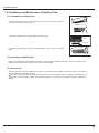
/LIWXSWKHIURQWSDQHOIURPLWVWZRHQGVDVVKRZQE\WKHDUURZGLUHFWLRQDQGWKHQ
UHPRYHWKHDLU¿OWHUDVVKRZQLQ)LJD
Fig. a
$WWDFKWKHKHDOWK\¿OWHURQWRWKHDLU¿OWHUDVVKRZQLQ)LJE
Fig. b
Air filter
Healthy filter
,QVWDOOWKHDLU¿OWHUSURSHUO\DORQJWKHDUURZGLUHFWLRQLQ)LJFDQGWKHQFORVHWKH
SDQHO
Fig.
c
&OHDQLQJDQG0DLQWHQDQFH
5HPRYHWKHKHDOWK\¿OWHUDQGUHLQVWDOOLWDIWHUFOHDQLQJDFFRUGLQJWRWKHLQVWDOODWLRQLQVWUXFWLRQ'RQRWXVHEUXVKRUKDUG
REMHFWVWRFOHDQWKH¿OWHU$IWHUFOHDQLQJEHVXUHWRGU\LWLQWKHVKDGH
6HUYLFH/LIH
7KHJHQHUDOVHUYLFHOLIHIRUWKHKHDOWK\¿OWHULVDERXWRQH\HDUXQGHUQRUPDOFRQGLWLRQ$VIRUVLOYHULRQ¿OWHULWLVLQHIIHFWLYH
ZKHQLWVVXUIDFHEHFRPHVEODFNJUHHQ
7KLVVXSSOHPHQWDU\LQVWUXFWLRQLVSURYLGHGIRUUHIHUHQFHWRWKHXQLWZLWKKHDOWK\¿OWHU,IWKHJUDSKLFVSURYLGHGKHUHLQDUH
GLIIHUHQWIURPWKHDFWXDOSURGXFWSOHDVHUHIHUWRWKHDFWXDOSURGXFW7KHTXDQWLW\RIKHDOWK\¿OWHUVLVEDVHGRQWKHDFWXDO
GHOLYHU\
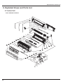
([SORGHG9LHZVDQG3DUWV/LVW
([SORGHG9LHZVDQG3DUWV/LVW
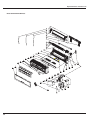
,QGRRU8QLW
0RGHO*:+1$.11%&,
25
24
23
22
21
20
19
18
17
16
15
14
13
12
11
10
9
8
7
6
5
4
3
2
40
1
39
38
37
36
35
34
33
32
31
30
29
28
27
26
45
44
43
42
41
([SORGHG9LHZVDQG3DUWV/LVW
1R
'HVFULSWLRQ
3URGXFW&RGH
3DUW&RGH
*:+1$.11%&,
&$1
4W\
)URQW3DQHO$VV\
)LOWHU6XE$VV\
6FUHZ&RYHU
(OHFWULF%R[&RYHU
)URQW&DVH
$[LOH%XVK
*XLGH/RXYHU
$LU/RXYHU
$LU/RXYHU
+HOLFRLGWRQJXH
$[LOH%XVK
5HDU&DVHDVV\
&URVV)ORZ)DQ
)DQ%HDULQJ
2*DVNHWVXEDVV\RI%HDULQJ
2*DVNHWRI&URVV)DQ%HDULQJ
5LQJRI%HDULQJ
5HPRWH&RQWUROOHU
'UDLQDJHKRVH
:DOO0RXQWLQJ)UDPH
(YDSRUDWRU$VV\
(YDSRUDWRU6XE$VV\
&RQQHFWLQJ&DEOH
&RQQHFWLQJ&DEOH
3RZHU&RUG
)URQWSDQHO%
6
'HFRUDWLYH6WULS
7XEH6HQVRU
$PELHQW7HPSHUDWXUH6HQVRU
0DLQ%RDUG
7HUPLQDO%RDUG
(OHFWULF%R[
(OHFWULF%R[$VV\
'LVSOD\%RDUG
&UDQN
6WHS0RWRU
5XEEHU3OXJ:DWHU7UD\
0RWRU3UHVV3ODWH
)DQ0RWRU
3LSH&ODPS
)XVH
-XPSHU
&DSDFLWRU&%%
6KLHOGER[HOHFWULFER[
(OHFWULF%R[&RYHU
7KHGDWDDERYHDUHVXEMHFWWRFKDQJHZLWKRXWQRWLFH
([SORGHG9LHZVDQG3DUWV/LVW
0RGHO*:+1$.11$&,
25
24
23
22
21
20
19
18
17
16
15
14
13
12
11
10
9
8
7
6
5
4
3
2
39
1
38
37
36
35
34
33
32
31
30
29
28
27
26
44
43
42
41
40
([SORGHG9LHZVDQG3DUWV/LVW
1R
'HVFULSWLRQ
3URGXFW&RGH
3DUW&RGH
*:+1$.11$&,
&$1
4W\
)URQW3DQHO$VV\
)LOWHU6XE$VV\
6FUHZ&RYHU
(OHFWULF%R[&RYHU
)URQW&DVH
$[LOH%XVK
*XLGH/RXYHU
$LU/RXYHU
$LU/RXYHU
+HOLFRLG7RQJXH
$[LOH%XVK
5HDU&DVHDVV\
&URVV)ORZ)DQ
)DQ%HDULQJ
2*DVNHWVXEDVV\RI%HDULQJ
2*DVNHWRI&URVV)DQ%HDULQJ
5LQJRI%HDULQJ
5HPRWH&RQWUROOHU
'UDLQDJH+RVH
:DOO0RXQWLQJ)UDPH
(YDSRUDWRU$VV\
(YDSRUDWRU6XE$VV\
&RQQHFWLQJ&DEOH
&RQQHFWLQJ&DEOH
3RZHU&RUG
'HFRUDWLYH6WULS
.
'LVSOD\%RDUG
7XEH6HQVRU
$PELHQW7HPSHUDWXUH6HQVRU
0DLQ%RDUG
7HUPLQDO%RDUG
(OHFWULF%R[
(OHFWULF%R[$VV\
&UDQN
6WHS0RWRU
5XEEHU3OXJ:DWHU7UD\
0RWRU3UHVV3ODWH
)DQ0RWRU
3LSH&ODPS
)XVH
-XPSHU
&DSDFLWRU&%%
6KLHOG%R[(OHFWULF%R[
(OHFWULF%R[&RYHU
7KHGDWDDERYHDUHVXEMHFWWRFKDQJHZLWKRXWQRWLFH
([SORGHG9LHZVDQG3DUWV/LVW
0RGHO*:+1%.11%&,
25
24
23
22
21
20
19
18
17
16
15
14
13
12
11
10
9
8
7
6
5
4
3
2
41
1
40
39
38
37
36
35
34
33
32
31
30
29
28
27
26
46
45
44
43
42
([SORGHG9LHZVDQG3DUWV/LVW
1R
'HVFULSWLRQ
3URGXFW&RGH
3DUW&RGH
*:+1%.11%&,
&$1
4W\
)URQW3DQHO$VV\
)LOWHU6XE$VV\
6FUHZ&RYHU
(OHFWULF%R[&RYHU
)URQW&DVH
$[LOH%XVK
*XLGH/RXYHU
$LU/RXYHU
$LU/RXYHU
+HOLFRLG7RQJXH
$[LOH%XVK
5HDU&DVHDVV\
&URVV)ORZ)DQ
)DQ%HDULQJ
2*DVNHWVXEDVV\RI%HDULQJ
2*DVNHWRI&URVV)DQ%HDULQJ
5LQJRI%HDULQJ
5HPRWH&RQWUROOHU
'UDLQDJH+RVH
:DOO0RXQWLQJ)UDPH
(YDSRUDWRU$VV\
(YDSRUDWRU6XSSRUW
&RQQHFWLQJ&DEOH
&RQQHFWLQJ&DEOH
3RZHU&RUG
)URQW3DQHO%
6
5HFHLYHU:LQGRZ
7XEH6HQVRU
$PELHQW7HPSHUDWXUH6HQVRU
0DLQ%RDUG
7HUPLQDO%RDUG
(OHFWULF%R[
7UDQVIRUPHU
(OHFWULF%R[$VV\
'LVSOD\%RDUG
&UDQN
6WHS0RWRU
5XEEHU3OXJ:DWHU7UD\
0RWRU3UHVV3ODWH
)DQ0RWRU
3LSH&ODPS
-XPSHU
&DSDFLWRU&%%
6KLHOG&RYHURI(OHFWULF%R[6XEDVV\
6KLHOG&RYHURI(OHFWULF%R[
(OHFWULF%R[&RYHU
7KHGDWDDERYHDUHVXEMHFWWRFKDQJHZLWKRXWQRWLFH
([SORGHG9LHZVDQG3DUWV/LVW
0RGHO*:+1%.11$&,
25
24
23
22
21
20
19
18
17
16
15
14
13
12
11
10
9
8
7
6
5
4
3
2
39
1
38
37
36
35
34
33
32
31
30
29
28
27
26
43
42
41
40
([SORGHG9LHZVDQG3DUWV/LVW
1R
'HVFULSWLRQ
3URGXFW&RGH
3DUW&RGH
*:+1%.11$&,
&$1
4W\
)URQW3DQHO$VV\
)LOWHU6XE$VV\
6FUHZ&RYHU
(OHFWULF%R[&RYHU
)URQW&DVH
$[LOH%XVK
*XLGH/RXYHU
$LU/RXYHU
$LU/RXYHU
+HOLFRLG7RQJXH
$[LOH%XVK
5HDU&DVHDVV\
&URVV)ORZ)DQ
)DQ%HDULQJ
2*DVNHWVXEDVV\RI%HDULQJ
2*DVNHWRI&URVV)DQ%HDULQJ
5LQJRI%HDULQJ
5HPRWH&RQWUROOHU
'UDLQDJH+RVH
:DOO0RXQWLQJ)UDPH
(YDSRUDWRU$VV\
(YDSRUDWRU6XE$VV\
&RQQHFWLQJ&DEOH
&RQQHFWLQJ&DEOH
3RZHU&RUG
'HFRUDWLYH6WULS
.
'LVSOD\%RDUG
7XEH6HQVRU
$PELHQW7HPSHUDWXUH6HQVRU
0DLQ%RDUG
7HUPLQDO%RDUG
(OHFWULF%R[
(OHFWULF%R[$VV\
&UDQN
6WHS0RWRU
5XEEHU3OXJ:DWHU7UD\
0RWRU3UHVV3ODWH
)DQ0RWRU
3LSH&ODPS
-XPSHU
&DSDFLWRU&%%
6KLHOG%R[(OHFWULF%R[
(OHFWULF%R[&RYHU
7KHGDWDDERYHDUHVXEMHFWWRFKDQJHZLWKRXWQRWLFH
([SORGHG9LHZVDQG3DUWV/LVW
0RGHO*:+1%.11$&,
([SORGHG9LHZVDQG3DUWV/LVW
1R
'HVFULSWLRQ
3URGXFW&RGH
3DUW&RGH
*:+1%.11$&,
&$1
6
4W\
)URQW3DQHO$VV\
)URQWSDQHO%
)LOWHU6XE$VV\
(OHFWULF%R[&RYHU
6FUHZ&RYHU
)URQW&DVH
$[LOH%XVK
*XLGH/RXYHU
$LU/RXYHU
$LU/RXYHU
+HOLFRLG7RQJXH
$[LOH%XVK
5HDU&DVHDVV\
&URVV)ORZ)DQ
)DQ%HDULQJ
2*DVNHWVXEDVV\RI%HDULQJ
2*DVNHWRI&URVV)DQ%HDULQJ
5LQJRI%HDULQJ
'UDLQDJHKRVH
:DOO0RXQWLQJ)UDPH
(YDSRUDWRU$VV\
(YDSRUDWRU6XSSRUW
&RQQHFWLQJ&DEOH
&RQQHFWLQJ&DEOH
3RZHU&RUG
7HPSHUDWXUH6HQVRU
$PELHQW7HPSHUDWXUH6HQVRU
0DLQ%RDUG
7HUPLQDO%RDUG
(OHFWULF%R[
7UDQVIRUPHU
(OHFWULF%R[$VV\
'LVSOD\%RDUG
&UDQN
6WHS0RWRU
5XEEHU3OXJ:DWHU7UD\
0RWRU3UHVV3ODWH
)DQ0RWRU
3LSH&ODPS
-XPSHU
&DSDFLWRU&%%
6KLHOGFRYHURI(OHFWULF%R[VXEDVV\
6KLHOGFRYHURI(OHFWULF%R[
(OHFWULF%R[&RYHU
5HPRWH&RQWUROOHU
7KHGDWDDERYHDUHVXEMHFWWRFKDQJHZLWKRXWQRWLFH
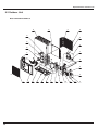
([SORGHG9LHZVDQG3DUWV/LVW
2XWGRRU8QLW
0RGHO*:+1$.11%&2
23
21
22
20
24
19
25
18
26
17
27
28
16
15
14
1
2
3
4
5
6
7
8
9
10
11
12
13
([SORGHG9LHZVDQG3DUWV/LVW
1R
'HVFULSWLRQ
3URGXFW&RGH
3DUW&RGH
*:+1$.11%&2
&$:
3
3
3
4W\
)URQWJULOO
)URQW3DQHO
&KDVVLV6XEDVV\
'UDLQDJH&RQQHFWHU
&RPSUHVVRUDQG)LWWLQJV
&RPSUHVVRU*DVNHW
0DJQHW&RLO
:D\9DOYH$VV\
ZD\9DOYH
6WUDLQHU$
&DSLOODU\6XEDVV\
9DOYH
9DOYH
%LJ+DQGOH
9DOYH6XSSRUW
5LJKW6LGH3ODWH6XE$VV\
7HUPLQDO%RDUG
(OHFWULF%R[$VV\
&DSDFLWRU&%%
&DSDFLWRU&%%
5HDUJULOO
&RQGHQVHU$VV\
7RS&RYHU6XE$VV\
&ODSERDUG6XE$VV\
0RWRU6XSSRUW6XE$VV\
<
)DQ0RWRU
6PDOO+DQGOH
$[LDO)ORZ)DQ
7KHGDWDDERYHDUHVXEMHFWWRFKDQJHZLWKRXWQRWLFH
([SORGHG9LHZVDQG3DUWV/LVW
0RGHO*:+1%.11%&2
22
21
20
19
23
18
24
17
25
16
26
27
15
14
13
1
2
3
4
5
6
7
8
9
10
11
12
([SORGHG9LHZVDQG3DUWV/LVW
1R
'HVFULSWLRQ
3URGXFW&RGH
3DUW&RGH
*:+1%.11%&2
&$:
3
3
3
4W\
)URQW*ULOO
)URQW3DQHO
&KDVVLV6XEDVV\
'UDLQDJH&RQQHFWHU
&RPSUHVVRUDQG)LWWLQJV
0DJQHW&RLO
:D\9DOYH$VV\
:D\9DOYH
6WUDLQHU$
&DSLOODU\6XEDVV\
9DOYH
9DOYH
%LJ+DQGOH
9DOYH6XSSRUW
5LJKW6LGH3ODWH6XE$VV\
7HUPLQDO%RDUG
(OHFWULF%R[$VV\
&DSDFLWRU&%%
&DSDFLWRU&%%
5HDU*ULOO
&RQGHQVHU$VV\
7RS&RYHU6XE$VV\
&ODSERDUG6XE$VV\
0RWRU6XSSRUW6XE$VV\
)DQ0RWRU
6PDOO+DQGOH
$[LDO)ORZ)DQ
7KHGDWDDERYHDUHVXEMHFWWRFKDQJHZLWKRXWQRWLFH
7URXEOHVKRRWLQJ
7URXEOHVKRRWLQJ
3UHFDXWLRQVEHIRUH3HUIRUPLQJ,QVSHFWLRQRU5HSDLU
%HFDXWLRXVGXULQJLQVWDOODWLRQDQGPDLQWHQDQFH'RRSHUDWLRQIROORZLQJWKHUHJXODWLRQVWRDYRLGHOHFWULFVKRFN
DQGFDVXDOW\RUHYHQGHDWKGXHWRGURSIURPKLJKDWWLWXGH
6WDWLFPDLQWHQDQFHLVWKHPDLQWHQDQFHGXULQJGHHQHUJL]DWLRQRIWKHDLUFRQGLWLRQHU
)RUVWDWLFPDLQWHQDQFHPDNHVXUHWKDWWKHXQLWLVGHHQHUJL]HGDQGWKHSOXJLVGLVFRQQHFWHG
G\QDPLFPDLQWHQDQFHLVWKHPDLQWHQDQFHGXULQJHQHUJL]DWLRQRIWKHXQLW%HIRUHG\QDPLFPDLQWHQDQFHFKHFNWKHHOHFWULFLW\
DQGHQVXUHWKDWWKHUHLVJURXQGZLUHRQWKHVLWH
&KHFNLIWKHUHLVHOHFWULFLW\RQWKHKRXVLQJDQGFRQQHFWLRQFRSSHUSLSHRIWKHDLUFRQGLWLRQHUZLWKYROWDJHWHVWHU$IWHUHQVXUH
LQVXODWLRQSODFHDQGWKHVDIHW\WKHPDLQWHQDQFHFDQEHSHUIRUPHG
7DNHVXI¿FLHQWFDUHWRDYRLGGLUHFWO\WRXFKLQJDQ\RIWKHFLUFXLWSDUWVZLWKRXW¿UVWWXUQLQJRIIWKHSRZHU
$WWLPHVVXFKDVZKHQWKHFLUFXLWERDUGLVWREHUHSODFHGSODFHWKHFLUFXLWERDUGDVVHPEO\LQDYHUWLFDOSRVLWLRQ
1RUPDOO\GLDJQRVHWURXEOHVDFFRUGLQJWRWKHWURXEOHGLDJQRVLVSURFHGXUHDVGHVFULEHGEHORZ5HIHUWRWKHFKHFNSRLQWVLQVHUYLFLQJ
ZULWWHQRQWKHZLULQJGLDJUDPVDWWDFKHGWRWKHLQGRRURXWGRRUXQLWV
1R7URXEOHVKRRWLQJ3URFHGXUH
&RQ¿UPDWLRQ
-XGJHPHQWE\)ODVKLQJ/('RI,QGRRU2XWGRRU8QLW
+RZWR&KHFN6LPSO\WKH0DLQ3DUW
3UHFDXWLRQVZKHQLQVSHFWLQJWKHFRQWUROVHFWLRQRIWKHRXWGRRUXQLW
$ODUJHFDSDFLW\HOHFWURO\WLFFDSDFLWRULVXVHGLQWKHRXWGRRUXQLWFRQWUROOHULQYHUWHU7KHUHIRUHLIWKHSRZHUVXSSO\LVWXUQHGRIIFKDUJH
FKDUJLQJYROWDJH'&9WR9UHPDLQVDQGGLVFKDUJLQJWDNHVDORWRIWLPH$IWHUWXUQLQJRIIWKHSRZHUVRXUFHLIWRXFKLQJWKH
FKDUJLQJVHFWLRQEHIRUHGLVFKDUJLQJDQHOHFWULFDOVKRFNPD\EHFDXVHG
&RQ¿UPDWLRQ
&RQ¿UPDWLRQRI3RZHU6XSSO\
&RQ¿UPWKDWWKHSRZHUEUHDNHURSHUDWHV21QRUPDOO\
&RQ¿UPDWLRQRI3RZHU9ROWDJH
&RQ¿UPWKDWSRZHUYROWDJHLV$&±±
,ISRZHUYROWDJHLVQRWLQWKLVUDQJHWKHXQLWPD\QRWRSHUDWHQRUPDOO\
-XGJHPHQWE\)ODVKLQJ/('RI,QGRRU2XWGRRU8QLW
7URXEOHVKRRWLQJ
'LVSOD\0HWKRGRI,QGRRU8QLW
1R
0DOIXQFWLRQ
1DPH
,QGRRUDPELHQW
WHPSHUDWXUH
VHQVRULVRSHQ
VKRUWFLUFXLWHG
,QGRRU
HYDSRUDWRU
WHPSHUDWXUH
VHQVRULVRSHQ
VKRUWFLUFXLWHG
3*PRWRU
LQGRRUIDQ
PRWRUGRHV
QRWRSHUDWH
(UURU
&RGH
,QGLFDWRUODPS
'XULQJEOLQNLQJ21IRU6
DQG2))IRU6
2SHUDWLRQ &22/
/DPS
/DPS
)
)
+
$&6WDWXV
3RVVLEOH&DXVHV
+($7
/DPS
2))
6DQG
EOLQNV
RQFH
7KHZLULQJWHUPLQDOEHWZHHQLQGRRU
7KHXQLWZLOOVWRSRSHUDWLRQ
DPELHQWWHPSHUDWXUHVHQVRUDQG
DVLWUHDFKHVWKHWHPSHUDWXUH
FRQWUROOHULVORRVHQHGRUSRRUO\FRQWDFWHG
SRLQW'XULQJFRROLQJDQG
7KHUH¶VVKRUWFLUFXLWGXHWRWULSRYHURI
GU\LQJRSHUDWLRQH[FHSWLQGRRU
WKHSDUWVRQFRQWUROOHU
IDQRSHUDWHVRWKHUORDGV
˄VXFK
,QGRRUDPELHQWWHPSHUDWXUHVHQVRULV
DVFRPSUHVVRURXWGRRUIDQ
GDPDJHG3OHDVHFKHFNLWE\UHIHUULQJ
ZD\YDOYH˅VWRSRSHUDWLRQ
WRWKHUHVLVWDQFHWDEOHIRUWHPSHUDWXUH
'XULQJKHDWLQJRSHUDWLRQWKH
VHQVRU
FRPSOHWHXQLWVWRSVRSHUDWLRQ
0DLQERDUGLVEURNHQ
2))
6DQG
EOLQNV
WZLFH
7KHZLULQJWHUPLQDOEHWZHHQLQGRRU
7KHXQLWZLOOVWRSRSHUDWLRQ
HYDSRUDWRUWHPSHUDWXUHVHQVRUDQG
DVLWUHDFKHVWKHWHPSHUDWXUH FRQWUROOHULVORRVHQHGRUSRRUO\FRQWDFWHG
SRLQW'XULQJFRROLQJDQG
7KHUH¶VVKRUWFLUFXLWGXHWRWKHWULSRYHU
GU\LQJRSHUDWLRQH[FHSWLQGRRURIWKHSDUWVRQFRQWUROOHU
IDQRSHUDWHVRWKHUORDGVVWRS ,QGRRUHYDSRUDWRUWHPSHUDWXUHVHQVRU
RSHUDWLRQ'XULQJKHDWLQJ
LVGDPDJHG3OHDVHFKHFNLWE\UHIHUULQJ
RSHUDWLRQWKHFRPSOHWHXQLW WRWKHUHVLVWDQFHWDEOHIRUWHPSHUDWXUH
VWRSVRSHUDWLRQ
VHQVRU
0DLQERDUGLVEURNHQ
2))6
DQGEOLQNV
WLPHV
7KHIHHGEDFNWHUPLQDORI3*PRWRULV
QRWFRQQHFWHGWLJKWO\
,QGRRUIDQRXWGRRUIDQ 7KHFRQWUROWHUPLQDORI3*PRWRULVQRW
FRPSUHVVRUDQGHOHFWULFKHDW FRQQHFWHGWLJKWO\
WXEHVWRSRSHUDWLRQPLQXWHV)DQEODGHURWDWHVXQVPRRWKO\GXHWR
ODWHUZD\YDOYHVWRSV LPSURSHULQVWDOODWLRQ
KRUL]RQWDOORXYHUVWRSVDWWKH 0RWRULVQRWLQVWDOOHGSURSHUO\DQG
FXUUHQWSRVLWLRQ
WLJKWO\
0RWRULVGDPDJHG
&RQWUROOHULVGDPDJHG
0DOIXQFWLRQ
SURWHFWLRQRI
MXPSHUFDS
&
2))6
DQGEOLQNV
WLPHV
7KHUH¶VQRWMXPSHUFDSRQWKH
FRQWUROOHU
2SHUDWLRQRIUHPRWHFRQWUROOHU
-XPSHUFDSLVQRWLQVHUWHGSURSHUO\
RUFRQWUROSDQHOLVDYDLODEOH
DQGWLJKWO\
EXWWKHXQLWZRQ¶WDFW
-XPSHUFDSLVGDPDJHG
&RQWUROOHULVGDPDJHG
3*PRWRU
LQGRRU
IDQFLUFXLW
PDOIXQFWLRQ
E\]HURFURVV
GHWHFWLRQ
8
2))6
DQGEOLQNV
WLPHV
2SHUDWLRQRIUHPRWHFRQWUROOHU
RUFRQWUROSDQHOLVDYDLODEOH &RQWUROOHULVGDPDJHG
EXWWKHXQLWZRQ¶WDFW
7URXEOHVKRRWLQJ
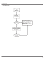
+RZWR&KHFN6LPSO\WKH0DLQ3DUW
))0DOIXQFWLRQ
Start
Is the wiring
terminal between temperature
sensor and the controller loosened or
poor ly contacted?
yes
Insert the temperature
sensor tightly
no
no
Is there short circuit due to trip over
of the par ts?
Malfunction is
eliminated.
yes
Make the parts upright
no
no
Is the te mperature
sensor normal according to the
Resistance Table?
Malfunction is
eliminated.
yes
no
Replace it with a
temperature sensor
of the same model
yes
no
Malfunction is
removed.
Replace the controller with
one of the same model
yes
End
yes
7URXEOHVKRRWLQJ
+0DOIXQFWLRQ
Possible causes:
1. Fan motor is locked;
2. The feedback terminal of PG motor is not connected tightly;
3. The control terminal of PG motor is not connected tightly;
4. Motor is damaged;
5. Malfunction of the rotation speed detection circuit of the mainboard.
chart below:
See the
“H6”is
displayed on
the unit.
Stir the fan blade
with a hand when
the unit is DE ENERGIZED.
Does the
blade rotate
unsmoothly?
Yes
Reinstall the motor
and the blade to
make it rotate
smoothly.
Is the
malfunction
eliminated?
No
No
Is the
feedback
terminal of PG
motor loose?
Yes
Insert the feedback
terminal tightly .
Is the
malfunction
eliminated?
No No
Is the
control terminal
of PG motor
loose?
Yes
Yes
Insert the control
terminal tightly.
Yes
Is the
malfunction
eliminated?
No
No
Re-energize
to turn on the unit;
measure within 1 min after the
louvers are opened whether the output
voltage on the control terminal
of the PG motor is over 50V?
No
No
Mainboard
malfunction;
Replace it.
Yes
Yes
Replace the fan
motor.
Is the
malfunction
eliminated?
Yes
End
7URXEOHVKRRWLQJ
&0DOIXQFWLRQ
Possible causes:
1. There is no jumper cap on the controller;
2. Jumper cap is not inserted properly and tightly;
3. Jumper cap is damaged;
4. Controller is damaged.
chart below:
See the
C5 is displayed
on the unit.
Is there jumper cap on the
controller?
Yes
No
Install a matching
jumper cap.
Is the
malfunction
eliminated?
No
Is the jumper cap inserted
incorrectly or improperly?
No
No
Yes
Re-insert the jumper
cap
Is the
malfunction
eliminated?
Yes
Replace the jumper
cap
Is the
malfunction
eliminated?
Yes
Yes
No
The mainboard is
defined abnormal
replace it
End
7URXEOHVKRRWLQJ
80DOIXQFWLRQ
“U8” is
displayed on
the unit.
Re-energize 1
minute after
de-erergization
Is“U8”
still displayed?
No
The unit returns to normal.
Conclusion: U8 is displayed due to
instant energization after deenergization while the capacitor
discharges slowly.
Yes
The zero-cross detection
circuit of the mainboard is
defined abnormal. Replace
the mainboard.
M alfunction is
eliminated.
7URXEOHVKRRWLQJ
$SSHQGL[
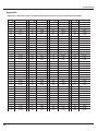
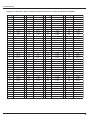
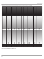
Appendix 1: Resistance Table of Ambient Temperature Sensor for Indoor and Outdoor Units(15K)
Temp(
) Resistance(kΩ)
Temp(
) Resistance(kΩ)
Temp(
)
Resistance(kΩ)
Temp(
)
Resistance(kΩ)
-19
138.1
20
18.75
59
3.848
98
1.071
-18
128.6
21
17.93
60
3.711
99
1.039
-17
121.6
22
17.14
61
3.579
100
1.009
-16
115
23
16.39
62
3.454
101
0.98
-15
108.7
24
15.68
63
3.333
102
0.952
-14
102.9
25
15
64
3.217
103
0.925
-13
97.4
26
14.36
65
3.105
104
0.898
-12
92.22
27
13.74
66
2.998
105
0.873
-11
87.35
28
13.16
67
2.896
106
0.848
-10
82.75
29
12.6
68
2.797
107
0.825
-9
78.43
30
12.07
69
2.702
108
0.802
-8
74.35
31
11.57
70
2.611
109
0.779
-7
70.5
32
11.09
71
2.523
110
0.758
-6
66.88
33
10.63
72
2.439
111
0.737
-5
63.46
34
10.2
73
2.358
112
0.717
-4
60.23
35
9.779
74
2.28
113
0.697
-3
57.18
36
9.382
75
2.206
114
0.678
-2
54.31
37
9.003
76
2.133
115
0.66
-1
51.59
38
8.642
77
2.064
116
0.642
0
49.02
39
8.297
78
1.997
117
0.625
1
46.6
40
7.967
79
1.933
118
0.608
2
44.31
41
7.653
80
1.871
119
0.592
3
42.14
42
7.352
81
1.811
120
0.577
4
40.09
43
7.065
82
1.754
121
0.561
5
38.15
44
6.791
83
1.699
122
0.547
6
36.32
45
6.529
84
1.645
123
0.532
7
34.58
46
6.278
85
1.594
124
0.519
8
32.94
47
6.038
86
1.544
125
0.505
9
31.38
48
5.809
87
1.497
126
0.492
10
29.9
49
5.589
88
1.451
127
0.48
11
28.51
50
5.379
89
1.408
128
0.467
12
27.18
51
5.197
90
1.363
129
0.456
13
25.92
52
4.986
91
1.322
130
0.444
14
24.73
53
4.802
92
1.282
131
0.433
15
23.6
54
4.625
93
1.244
132
0.422
16
22.53
55
4.456
94
1.207
133
0.412
17
21.51
56
4.294
95
1.171
134
0.401
18
20.54
57
4.139
96
1.136
135
0.391
19
19.63
58
3.99
97
1.103
136
0.382
7URXEOHVKRRWLQJ
Appendix 2: Resistance Table of Ambient Temperature Sensor for Indoor and Outdoor Units(20K)
Temp(
-19
) Resistance(kΩ)
181.4
Temp(
20
) Resistance(kΩ)
25.01
Temp(
59
)
Resistance(kΩ)
5.13
Temp(
98
)
Resistance(kΩ)
1.427
-18
171.4
21
23.9
60
4.948
99
1.386
-17
162.1
22
22.85
61
4.773
100
1.346
-16
153.3
23
21.85
62
4.605
101
1.307
-15
145
24
20.9
63
4.443
102
1.269
-14
137.2
25
20
64
4.289
103
1.233
-13
129.9
26
19.14
65
4.14
104
1.198
-12
123
27
18.13
66
3.998
105
1.164
-11
116.5
28
17.55
67
3.861
106
1.131
-10
110.3
29
16.8
68
3.729
107
1.099
-9
104.6
30
16.1
69
3.603
108
1.069
-8
99.13
31
15.43
70
3.481
109
1.039
-7
94
32
14.79
71
3.364
110
1.01
-6
89.17
33
14.18
72
3.252
111
0.983
-5
84.61
34
13.59
73
3.144
112
0.956
-4
80.31
35
13.04
74
3.04
113
0.93
-3
76.24
36
12.51
75
2.94
114
0.904
-2
72.41
37
12
76
2.844
115
0.88
-1
68.79
38
11.52
77
2.752
116
0.856
0
65.37
39
11.06
78
2.663
117
0.833
1
62.13
40
10.62
79
2.577
118
0.811
2
59.08
41
10.2
80
2.495
119
0.77
3
56.19
42
9.803
81
2.415
120
0.769
4
53.46
43
9.42
82
2.339
121
0.746
5
50.87
44
9.054
83
2.265
122
0.729
6
48.42
45
8.705
84
2.194
123
0.71
7
46.11
46
8.37
85
2.125
124
0.692
8
43.92
47
8.051
86
2.059
125
0.674
9
41.84
48
7.745
87
1.996
126
0.658
10
39.87
49
7.453
88
1.934
127
0.64
11
38.01
50
7.173
89
1.875
128
0.623
12
36.24
51
6.905
90
1.818
129
0.607
13
34.57
52
6.648
91
1.736
130
0.592
14
32.98
53
6.403
92
1.71
131
0.577
15
31.47
54
6.167
93
1.658
132
0.563
16
30.04
55
5.942
94
1.609
133
0.549
17
28.68
56
5.726
95
1.561
134
0.535
18
27.39
57
5.519
96
1.515
135
0.521
19
26.17
58
5.32
97
1.47
136
0.509
7URXEOHVKRRWLQJ
Appendix 3: Resistance Table of Ambient Temperature Sensor for Indoor and Outdoor Units(50K)
Temp˄ć˅ Resistance(kΩ)
Temp.˄ć˅ Resistance(kΩ)
Temp.˄ć˅ Resistance(kΩ)
-29
853.5
10
98
49
18.34
88
4.754
-28
799.8
11
93.42
50
17.65
89
4.609
-27
750
12
89.07
51
16.99
90
4.469
-26
703.8
13
84.95
52
16.36
91
4.334
-25
660.8
14
81.05
53
15.75
92
4.204
-24
620.8
15
77.35
54
15.17
93
4.079
-23
580.6
16
73.83
55
14.62
94
3.958
-22
548.9
17
70.5
56
14.09
95
3.841
-21
516.6
18
67.34
57
13.58
96
3.728
-20
486.5
19
64.33
58
13.09
97
3.619
-19
458.3
20
61.48
59
12.62
98
3.514
-18
432
21
58.77
60
12.17
99
3.413
-17
407.4
22
56.19
61
11.74
100
3.315
-16
384.5
23
53.74
62
11.32
101
3.22
-15
362.9
24
51.41
63
10.93
102
3.129
-14
342.8
25
49.19
64
10.54
103
3.04
-13
323.9
26
47.08
65
10.18
104
2.955
-12
306.2
27
45.07
66
9.827
105
2.872
-11
289.6
28
43.16
67
9.489
106
2.792
-10
274
29
41.34
68
9.165
107
2.715
-9
259.3
30
39.61
69
8.854
108
2.64
-8
245.6
31
37.96
70
8.555
109
2.568
-7
232.6
32
36.38
71
8.268
110
2.498
-6
220.5
33
34.88
72
7.991
111
2.431
-5
209
34
33.45
73
7.726
112
2.365
-4
198.3
35
32.09
74
7.47
113
2.302
-3
199.1
36
30.79
75
7.224
114
2.241
-2
178.5
37
29.54
76
6.998
115
2.182
-1
169.5
38
28.36
77
6.761
116
2.124
0
161
39
27.23
78
6.542
117
2.069
1
153
40
26.15
79
6.331
118
2.015
2
145.4
41
25.11
80
6.129
119
1.963
3
138.3
42
24.13
81
5.933
120
1.912
4
131.5
43
23.19
82
5.746
121
1.863
5
125.1
44
22.29
83
5.565
122
1.816
6
119.1
45
21.43
84
5.39
123
1.77
7
113.4
46
20.6
85
5.222
124
1.725
8
108
47
19.81
86
5.06
125
1.682
9
102.8
48
19.06
87
4.904
126
1.64
1RWH7KHLQIRUPDWLRQDERYHLVIRUUHIHUHQFHRQO\
Temp.˄ć˅ Resistance(kΩ)
5HPRYDO3URFHGXUH
5HPRYDO3URFHGXUH
5HPRYDO3URFHGXUHRI,QGRRU8QLW
:DUQLQJ
7DNHPRGHO *:+1%.11%&DVH[DPSOH
Step
%HVXUHWRZDLWIRUDPLQLPXPRIPLQXWHVDIWHU
WXUQLQJRIIDOOSRZHUVXSSOLHVEHIRUHGLVDVVHPEO\
Procedure
1.
Before disassembly
2.
Remove indicator
1
Open front panel
2
Remove screws fixing display board
and then remove indicator.
display board
5HPRYDO3URFHGXUH
Step
3.
Procedure
Remove front panel and filter
front panel
1
Open front panel and slide rotating shaft
of front panel along groove fixing front
panel to remove the front panel.
2
Push filter inwards and then lift it to
remove filter.
filter
4
Remove horizontal louver
electric box cover 2
1
Remove 1 screw fixing electric box cover
2 and then remove electric box cover 2.
2
Remove axle sleeve of horizontal louver
and then bend the horizontal louver to
draw it outwards to remove it.
horizontal louver
axle sleeve
5HPRYDO3URFHGXUH
Step
5
1
Procedure
Remove front case
Loosen clasps between vertical louver
and rear case. Then remove vertical
louver.
vertical louver1
vertical louver 2
screws
front case
2
Remove screw caps on front case and
then the screws on front case. Loosen
clasps of front case. Then remove front
case.
Remove electric box
electric box cover 1
1
Loosen clasps of electric box and then
remove electric box cover 1.
2
Remove connection screws between
electric box assy
electric box and rear case. Unplug wiring
terminal and loosen clasps. Remove
connection screws between ground wire
and evaporator. Unplug indoor temp
sensor and then remove electric box.
5HPRYDO3URFHGXUH
Step
7
Procedure
Remove evaporator
pipe clamp
1
Turn
over
rear
case
and
remove
connection screws between connecting
pipe clamp and rear case. Loosen clasps
between connecting pipe clamp and rear
case. Then remove connecting pipe
clamp.
evaporator Dssy
2
Loosen
connection
screws
among
evaporator, motor clamp and rear case.
Loosen clasps between evaporator and
rear case. Slightly adjust pipeline. Then
remove evaporator.
Remove cross flow fan blade and motor
motor clamp
1
Remove 4 connection screws between
motor clamp and rear case. Then
remove motor clamp.
5HPRYDO3URFHGXUH
Step
Procedure
cross flow fan blade
2
Remove cross flow fan blade and motor.
Remove connection screws between
motor
cross flow fan blade and motor shaft.
Then remove motor.
3
Remove holder of bearing ring and then
remove connection screws fixing step
motor. Then remove step motor.
O-Gasket sub-assy of Bearing
step motor
5HPRYDO3URFHGXUH
5HPRYDO3URFHGXUHRI2XWGRRU8QLW
:DUQLQJ
%HVXUHWRZDLWIRUDPLQLPXPRIPLQXWHVDIWHU
WXUQLQJRIIDOOSRZHUVXSSOLHVEHIRUHGLVDVVHPEO\
1. Before disassembly
2. Remove big handle
Remove the connection screw fixing the big handle
and then remove the handle.
big handle
3. Remove top panel
top panel
Remove connection screws connecting the top
panel with the front panel and the right side plate,
and then remove the top panel.
5HPRYDO3URFHGXUH
4. Remove front grille
Remove connection screws between the front
grille and the front panel. Then remove the front
grille.
front grille
5. Remove front panel
Remove connection screws connecting the front
panel with the chassis and the motor support,
and then remove the front panel.
front panel
6. Remove right side plate
right side plate
Remove connection screws connecting the
right side plate with the chassis, the valve
support and the electric box. Then remove
the right side plate.
7. Remove axial flow blade
Remove the nut on the blade and then remove
the axial flow blade.
axial flow blade
5HPRYDO3URFHGXUH
8. Remove motor and motor support
motor support
Remove the 4 tapping screws fixing the motor and
disconnect the leading wire insert of the motor. Then
remove the motor.
Remove the 2 tapping screws fixing the motor
support and lift the motor support to remove it.
motor
9. Remove electric box
electric box
Remove screws fixing the electric box subassembly;
loosen the wire bundle and unplug the wiring
terminals. Then lift the electric box to remove it.
10. Remove isolation sheet
Remove the 3 screws fixing the isolation sheet and
then remove the isolation sheet.
isolation sheet
11. Remove soundproof sponge
Remove the soundproof sponge wrapping the
compressor.
soundproof sponge
5HPRYDO3URFHGXUH
12. Remove magnet coil
magnet coil
Remove the screw fixing the magnet coil and then
remove the coil.
13. Remove valves and 4-way valve subassembly
4-way
valve
Unsolder welding joint connecting the capillary,
the valve and the outlet pipe of condenser to
remove the capillary. Do not block the capillary
with welding slag during unsoldering.
Remove the 2 screws fixing the gas valve and
unsolder the welding point between the gas valve
and the air-return pipe to remove the gas valve.
(NOTE: Discharge the refrigerant completely
before unsoldering; when unsoldering, wrap the
gas valve with a wet cloth completely to avoid
damage to the valve caused by high temperature).
Remove the 2 screws fixing the liquid valve and
unsolder the welding joint connecting the liquid
valve to the Y-type pipe to remove the liquid valve.
Unsolder the welding joint connecting the 4-way
valve, the compressor and the condenser to
remove the 4-way valve.
14. Remove compressor
liquid valve
gas valve
foot nuts
compressor
Remove the foot nuts on the compressor and then
remove the compressor.