1
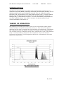
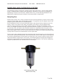
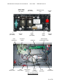
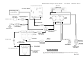
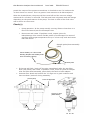
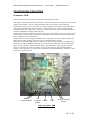
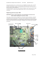
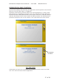
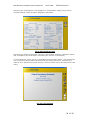
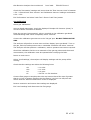
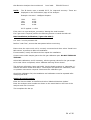
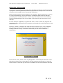
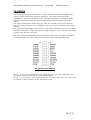
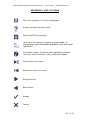
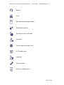
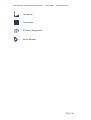
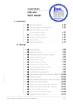
680 Emission Analyser
Service Manual
TES1567 Issue C
June 2008
680 Emission Analyser Service Manual
June 2008
TES1567
Issue C
This page intentionally blank
2 of 36
680 Emission Analyser Service Manual
June 2008
TES1567
Issue C
CONTENTS
THEORY OF OPERATION ........................................................................... 5
POWER SUPPLY ........................................................................................ 6
SAMPLING AND FILTRATION SYSTEM ...................................................... 7
Sampling Gas ........................................................................................... 7
Auto Zero ............................................................................................... 10
Calibration ............................................................................................. 11
POTENTIAL PROBLEMS AND CAUSES ...................................................... 12
Gas Flow Restricted................................................................................ 12
Leak Test Failure .................................................................................... 12
PROCESSING CIRCUITRY ....................................................................... 14
Processor PCB ........................................................................................ 14
Replacing the Processor PCB .................................................................. 15
OPERATION AND CONTROL .................................................................... 17
SERVICE MODE ....................................................................................... 20
Set-up Function ...................................................................................... 22
Replacing the Analyser ........................................................................... 25
IR BENCH ............................................................................................... 26
Bench Diagnostics .................................................................................. 27
Replacing the Bench ............................................................................... 28
Fault codes ............................................................................................. 29
List of Fault Codes .................................................................................. 30
TECHNICAL SPECIFICATIONS ................................................................. 31
APPENDIX 1 LIST OF ICONS ................................................................... 33
AFTER SALES SERVICE ........................................................................... 36
3 of 36
680 Emission Analyser Service Manual
June 2008
TES1567
Issue C
This page intentionally blank
4 of 36
680 Emission Analyser Service Manual
June 2008
TES1567
Issue C
INTRODUCTION
The 680 is a microprocessor controlled exhaust gas analyser employing nondispersive Infra Red (NDIR) measuring techniques, and designed primarily for the
legislative MOT test on petrol/CNG/LPG vehicles. The unit measures Carbon
Monoxide (CO), Hydrocarbons (HC) and Carbon Dioxide (CO2). A further channel
Oxygen (O2) is measured using a chemical cell. A fifth compound, Oxides of
Nitrogen (NOx) is available as an option. The unit automatically compensates for
zero drift by performing a zero check 5 minutes, 15 minutes and every 30
minutes thereafter from switch on.
THEORY OF OPERATION
Non-dispersive infrared spectrometry relies on the way different gases absorb
infrared radiation at specific frequencies (see fig 1.). The amount of radiation
absorbed can be used to calculate the concentration of a sample gas. The sample
gas is passed through the sample cell where an infrared source is positioned at
one end and an array of detectors at the other. Placed just in front of the detector
array is a series of filters, designed to be transparent only to the selected
frequencies of radiation. This arrangement allows the concentrations of several
gases to be determined.
Fig 1 Absorption Spectra
5 of 36
680 Emission Analyser Service Manual
June 2008
TES1567
Issue C
POWER SUPPLY – PWRS0026
There is a 65W multi-rail switched mode power supply providing power for the
analyser. Input range is 100 – 240V AC, 50/60Hz and no adjustments are
necessary within this range.
The DC outputs are:
+5V ±0.25V
+12V ±1.0V
-12V ±1.0V
The outputs can be measured at the power connector of the processor bd SK4 as
shown in fig 2.
For
part number see TES1601
PSA80504
SK4
0V
-12V
+5V
+12V
Fig 2 Power Supply Connections
Power for the processor is derived from the +5V rail. The IR bench, pump and
solenoid are driven from the +12V rail. The -12V rail is used solely for the
amplifier of the pressure transducer and for RS232 communications when fitted.
The Processor board requires programming according to the specific
customer requirements. See appendix 2 for further details
6 of 36
680 Emission Analyser Service Manual
June 2008
TES1567 Issue C
SAMPLING AND FILTRATION SYSTEM
The sampling system comprises a sample probe with 8.5m hose, 12V DC dual headed
pump, 3 stage filtration system and changeover solenoid for use when the analyser is
performing a routine zero function. Please refer to Fig. 4 and drawings AS09121 and
AS08754 for details and part numbers of the pneumatics components.
Sampling Gas
Please refer to Figs 3 & 4. Gas is drawn from the vehicle exhaust by means of the pump,
via the sample probe, hose and filtration system. The gas flow at the sample inlet of the
analyser, given clean filters, is around 8L/min.
On UK analysers there is a preconditioning water trap (shown below) fitted to the host
trolley. There is no filter in this trap, its purpose is to help to cool the sample and
remove a large proportion of the water vapour before it reaches the analyser. From
there, the sample is passed through a dual bowl filtration system. The first bowl consists
of a primary filter and water trap. Residual moisture is separated from the gas in this
bowl and the condensed liquids are removed from the bottom of the bowl by the liquid
head of the pump. There is a 75 micron nylon filter to remove the larger particulates and
a pump filter to prevent contamination of the liquid head.
The dry gas is then passed through the gas filter bowl which houses a 0.6 micron filter to
remove the residual contaminants. This is followed by a bench filter which is fitted purely
to prevent contamination of the bench and internals in the event of failure of any of the
external filtration components. From there, the sample passes through the changeover
solenoid and gas head of the pump and then on to the IR bench. The cell for measuring
oxygen is positioned in the exhaust tract of the sample.
Preconditioning Water Trap
Fitted to Host Trolley
7 of 36
680 Emission Analyser Service Manual
Water Trap &
Primary Filter
(FILT0041)
Zero Filter
(FILT0029)
Flow
Transducer
1.5psi
Check Valve
June 2008
Gas Filter
(FILT0040)
Calibration Gas
Port
Pump
Filter
(FILT0048)
Sample
Inlet
Processor
Board
3psi
Check Valve
TES1567 Issue C
IR Bench
Changeover
Solenoid
Bench
Filter
(FILT0048)
Water
Outlet
Oxygen
Cell
Sample
Outlet
Power Supply
(underneath cover)
Pump
Gas head
Pump
Liquid head
Fig 3 Components
8 of 36
680 Emission Analyser Service Manual
June 2008
TES1567 Issue C
IR bench
(TRDU0134)
For
part number see TES1601
PSA80504
PSA80491
Processor Board
Power Supply Unit
(PWRS0026)
Zero Filter 1.5 psi Check Valve
(VALV0019)
(FILT0029)
Gas
Head
Autozero Port
Liquid
Head
Pump
(AS09287)
Flow Transducer
3.0 psi Check valve
(VALV0020)
1
Cal Gas Port
2
Changeover Solenoid
(VALV0033)
Approx
5 L/min
Bench Filter
(FILT0048)
Approx
5 L/min
Gas Filter
Sample Inlet
Water Trap
& Primary Filter
Oxygen Cell
(TRDU0067)
Pump Filter
(FILT0048)
Water Outlet
From Sample
Hose/Probe
Sample Outlet
(PFIT0010)
Flow approx 8L/min
Water Trap fitted to
host trolley
(FL5004A)
Manifold
(PFIT0049)
Fig 4 Flow Diagram
The Processor board requires programming according to the specific customer
requirements. See appendix 2 for further details
9 of 36
680 Emission Analyser Service Manual
June 2008
TES1567 Issue C
For part number see TES1601
Cell
Cell
Fig. 4a Interconnection Diagram
The Processor board requires programming according to the specific customer
requirements. See appendix 2 for further details
10 of 36
680 Emission Analyser Service Manual
June 2008
TES1567 Issue C
Auto Zero
The analyser performs regular zero operations to ensure continued accuracy. The
time intervals between zeroes from switch on are: 5 minutes; 15 minutes; then
every 30 minutes thereafter. A manual zero can also be performed from the
‘Tools & Setup’ menu. The analyser will also perform a zero if any of the gas
channels drift negative by more than the Maximum Permissible Error (MPE).
These are as follows:
HC -12ppm
CO -0.06%
CO2 -0.5%
O2 -0.1%
When a zero is initiated, the changeover solenoid (see fig 4) is energized. Gas
flow to the bench is changed from the filters and sample inlet to the autozero port
via the Zero filter and 1.5 psi check valve. The vacuum of the pump is great
enough to open the 1.5 psi valve but not the 3.0 psi one (both devices are one
way valves). This ensures that clean air for the zero is pulled only through the
charcoal filter. The purpose of this charcoal filter is to remove any residual
ambient Hydrocarbons thus ensuring a more accurate zero.
The zero routine consists of a 30 second purge to ensure that there is no sample
gas left in the system followed by the zero command to the IR bench. This will
typically take a further 10 seconds for the bench to respond.
After the zero, the analyser will check the oxygen cell. Cell millivolts at this point
must be within 5 – 13mV for the cell to pass. This is followed by temperature
compensation of the pressure transducer. No operator intervention is necessary.
Calibration
When calibrating, the correct tag values must be entered. These are the gas
bottle concentrations as shown on the bottle certificate. The sample cell pressure
is also displayed at this point and should be checked to ensure that it is within
±20mbar of ambient.
The analyser will then perform an Autozero as described above. After the zero,
the calibration gas bottle should be connected to the Gas Cal port, and the bottle
pressure set using a digital manometer to between 1350 and 1450mbar.
It may be noted that the Calibration Gas Port uses the same changeover solenoid
as the Autozero. The bottle pressure (when set correctly) is high enough to open
the 3.0 psi valve but, at the same time, ‘reverse bias’ the 1.5 psi one and ensure
that it stays shut. This forces calibration gas through the solenoid and pump head
and thus on to the bench avoiding the filters and sampling system.
The analyser will then perform a gas purge. This uses the oxygen cell to ensure
that a calibration gas is actually present. Attempting to perform a calibration on
ambient air may cause the bench to corrupt its internal memory settings thus
rendering it inoperable. To prevent this, the oxygen reading must fall to 0.2% or
less for the calibration to continue. There is a 120 second countdown at this
point. If the limit is not reached within the countdown the calibration will fail.
After the purge the calibration command will be sent to the IR bench. No operator
intervention is necessary. Following the calibration, the gas must be connected to
the sample inlet and the pressure set to the ambient reading. The analyser will
then check that the readings are within ±3% of the entered tag values as set by
the legislation. Again, the oxygen cell is used to check for the presence of the
calibration gas. The limit is 0.1% to allow for the ‘beating effect’ of the pump.
This check also has a 120 second countdown. Failure to reach the limit will result
in failure of the calibration.
11 of 36
680 Emission Analyser Service Manual
June 2008
TES1567 Issue C
POTENTIAL PROBLEMS AND CAUSES
Gas Flow Restricted
Restriction of the gas to the point where the flow at the inlet is 4L/min or less.
The flow transducer (see fig. 4) continuously monitors the ‘vacuum’ after the
filters to ensure that the flow is at a reasonable level and response time of the
analyser is not too badly affected by contamination/blocked sample pipe etc. The
output of the transducer is in volts and when the vacuum reaches a predefined
point, set up on production and usually between 1.5 and 2.5V (refer to test
specification TS1292 for set up procedure), the analyser will trigger a ‘Gas Flow
Restricted’ message.
Common causes:
Heavily contaminated filters or blocked sample hose/probe.
Another possible, but much less likely cause is the incorrect setting/failure of the
flow transducer and associated circuitry.
Check(s)
Disconnect sample hose from analyser. If problem cured, blow out
hose/probe assembly with airline. Inspect flexible probe end for
damage/kinks.
Unscrew filter bowls. If problem cured, replace filters. The nylon filter may
be washed with warm soapy water. DO NOT USE SOLVENTS.
Ensure no kinking or pinching of pipe work.
Select ‘Information’ page. Check pneumatics settings and ensure that
that: Flow Vacuum Limit between 1.5 & 2.5
Zero & Calibration Vacuums between 0.3 and 0.5
Leak Test Failure
During normal operation, the 680 forces a leak test every day from switch on.
One of the most common faults in a gas analyser is failure of this test.
Common causes:
Faulty joints, particularly in sample probe/hose assembly and between the two
filter bowls.
Damaged 'O' ring seals of filter bowls, particularly if filters have just been
changed.
Occasional contamination in liquid head of pump preventing the valves from
closing correctly.
Check(s)
The test is performed in two parts:
I. Threshold test
II. Leak test
The threshold test is performed to ensure that the pump is in reasonable
condition and is actually running. When a leak test is performed, the PC will run
the pump for 20 seconds to allow the vacuum to stabilise. At the end of this
12 of 36
680 Emission Analyser Service Manual
June 2008
TES1567 Issue C
period the output of the pressure transducer is checked to see if it is above the
3V limit shown on screen. This is a generic limit common to all 680 analysers.
After the threshold test, the pump will be turned off and the vacuum voltage
monitored for a further 10 seconds. The leak test limit is dynamic and will change
depending on the performance of the pump. The limit is 95% of the final value
and is shown on the screen.
Check(s)
•
Pump operation. Is the pump actually running? Ensure that there is a
flow of at least 6L/min at the sample inlet.
•
Disconnect and retest. If problem cured, inspect joints for
leaks/damage. Also ensure flexible probe is not damaged. In cases of
extreme exhaust gas temperature the p.t.f.e liner may melt and cause
leak test failure.
Sample probe/hose assembly
(SP8)
Check flexible p.t.f.e liner inside
braiding. Replace the flexible probe
end if necessary (SP8X).
Check joints
•
•
If the test still fails, ‘pinch off’ the pipe immediately after the gas filter
bowl (see below) and retest. If problem cured, check all joints on sample
inlet and filter bowl assembly, particularly the bowl to bowl adapter.
Unscrew filter bowls and ensure the 'O' rings are in good condition and
have not been 'pinched' during assembly.
Check joints
Pinch off pipe here
Check ‘O’ rings
(SEAL0036)
Check joints
13 of 36
680 Emission Analyser Service Manual
June 2008
TES1567 Issue C
PROCESSING CIRCUITRY
Processor PCB
Refer to drawing AS09094 for schematic and layout of PCB.
The 680 is controlled entirely by the PC. No autonomous functions are performed
within the module. The PC communicates with the module via a USB link.
Commands are sent over the link to a small processor bd which interprets them
and communicates with the IR bench via an RS232 link. The processor board
consists of an 18F series 'PIC'. There is a real time clock (RTC) on board which is
used for calibration dates, leak test etc.
When the module is powered, LED D4 (See fig 5) will flash once per second. This
is driven by the RTC and a processor ‘interrupt’ and indicates that the processor
core is healthy and functioning.
When there is communication between the computer and the module, LEDs D5
and D6 will flash rapidly. These are the ‘communications’ LEDs.
When the computer application is started, it will force the module to perform an
autozero and then display ‘Main Menu’ (control and operation will be discussed
later in this manual). While in Main Menu, the application will poll the module
every 2 seconds to check its status. This can be seen by D5 and D6 flashing
briefly. If an autozero is required the computer will automatically initiate it. LED
D7 is not currently used.
D5 & 6
Communications
D4
Processor
Healthy
R7
Offset
R9
Gain
Pump & Solenoid
drivers
Fig 5 Processor PCB
14 of 36
680 Emission Analyser Service Manual
June 2008
TES1567 Issue C
Pump and Solenoid drive is achieved via two ‘MOSFET’ transistors TR1 and TR2.
All Data and Program memory on the board is held within the Processor. This
device is ‘electrically erasable’ so reprogramming the analyser can be performed
by the host PC via the serial link.
Communications to the bench are through the RS232 device IC6 and the 20 way
connector SK6. The bench also obtains power from the 12V rail through this
connector.
Replacing the Processor PCB
WARNING: Always ensure that the correct antistatic precautions are
taken when handling the Processor PCB.
The board is secured to the chassis by 3, M3 screws (see fig 6 below). Carefully
note positions and orientation of the bench, power supply, solenoid and pump
connectors and disconnect them. Disconnect the 4mm silicone vacuum pipe from
P2 of the vacuum transducer. Undo and remove the three fixing screws. The PCB
may then be removed from the analyser. Refitting is the reverse of the removal
procedure
Coloured tracer
Denoting Pin 1
Bench Connector
SK6
Fixing screw
Power Connector
SK4
Solenoid
Connector
SK2
Pump
Connector
SK1
Vacuum
Pipe
Fixing screws
Fig 6 PCB Fixings
15 of 36
680 Emission Analyser Service Manual
June 2008
TES1567 Issue C
After replacing the PCB it will be necessary to perform some basic set up
functions. These include setting the flow limits, serial number and performing a
calibration to ensure that the recalibration date is set. Refer to the 'SET-UP
Function' procedure in the ‘Service Mode' section for further details.
Note: If the PCB has previously been used in another analyser, a problem
may be encountered with the audit log stored on the PC.
16 of 36
680 Emission Analyser Service Manual
June 2008
TES1567 Issue C
OPERATION AND CONTROL
As previously stated, from start up, the application will first perform an autozero.
After the zero the ‘Main Menu’ is displayed.
Legislative and market variations affect only the language and, in some cases,
the inclusion of a ‘legislative procedure’ icon. Fig 7 below shows the difference
between the basic MID (Measurement Instruments Directive) compliant analyser
and the UK Analyser which must include the MOT procedure. All operations are
performed using the icons in the toolbar on the right hand side of the screen.
UK Legislative
Procedure
Fig 7 Main Menu
A description of each icon is displayed by holding the mouse cursor over that
icon. For a list of all icons refer to Appendix 1.
17 of 36
680 Emission Analyser Service Manual
June 2008
TES1567 Issue C
Selecting the ‘Information’ icon displays an ‘Information’ page (Fig 8) which
includes details useful for basic diagnostic purposes.
Fig 8 Information Page
Included are details of program versions, pneumatics settings, calibration dates
and a snapshot of the IR bench raw data (see section on IR Bench).
A ‘Tools & Setup’ menu (Fig 9) is available from the ‘Main Menu’. This allows the
user to perform other basic functions such as setting the time, performing a
manual zero, performing a leak test etc. Service mode is also accessed from this
menu.
Fig 9 Tools & Setup
18 of 36
680 Emission Analyser Service Manual
June 2008
TES1567 Issue C
It is also possible to view the ‘Audit Log’ (Fig 10) from this screen. All analysers
approved for sale in Europe from October 2006 must have an Audit Log which
records updates/changes to the software plus the analyser serial number etc.
Fig 10 Audit Log
19 of 36
680 Emission Analyser Service Manual
June 2008
TES1567 Issue C
SERVICE MODE
Set up of the analyser is performed from the ‘Service Mode’. There are two
methods of entering Service mode dependent on the legislative market. On UK
analysers, an Authorisation code is required (Fig 11).
Fig 11 Service Mode – Authorisation enable
When the code is entered the service menu will automatically be displayed (Fig
12). The analyser will then stay in service mode until the ‘exit’ icon is selected.
Fig 12 Service Mode
20 of 36
680 Emission Analyser Service Manual
June 2008
TES1567 Issue C
For Basic MID compliant analysers (i.e. those sold outside the UK), service
activation is achieved by shorting the pins of LK2 on the processor board together
(refer to Figs 13 & 14). When the pins are shorted, the analyser will automatically
enter service mode and stay there until exit is selected.
Fig 13 Service Mode - Jumper Enable
Short pins of
LK2
Fig 14 Service Jumper
21 of 36
680 Emission Analyser Service Manual
June 2008
TES1567 Issue C
SET-UP Function
Test equipment required: Flow Gauge,
0-12 litres/min.
Manometer, digital 0 - 2000mbar.
Mixture gas comprising: 3.5% Vol CO Nom.
14.0% Vol CO2 Nom.
2000ppm Vol C3H8 Nom.
Balance N2
Connect unit to mains supply and switch on.
Time & Date
Enter the ‘Service Mode’ (An Authorisation Code will be required), and select 'Date &
Time'. Check that both the date and time are correct. If they are not correct then
set the ‘date’ and ‘time’, confirm with ‘Continue’ then ‘Exit’.
Oxygen Cell
Select ‘Oxygen cell’.
Ensure that the oxygen cell is correctly connected and then select 'Install new cell'
to perform an installation. If unsuccessful, rectify the fault and then repeat the
installation.
Exit ‘Oxygen cell’.
Flow Setup
Connect the flow gauge to the sample probe inlet. Select ‘Live Readings’, check that
the pump turns on and that a flow of greater than 6.0 L/min is present. Exit ‘Live
Readings’, select ‘Oxygen cell’ and click ‘Retest’. This will force the analyser to
perform an autozero. During the autozero, ensure that the flow at the sample inlet
is less than 5.0 L/min and a flow is present at the inlet of the charcoal filter.
Ensure that NO flow is present at the ‘cal gas port’.
Disconnect the pipe to the pressure sensor and connect the digital manometer
(ensure that the connection is gas tight). Block off the sample inlet and select live
readings. Check that the reading on the manometer falls to less than 400mbar.
Allow the reading to stabilise and note the final value displayed on the manometer.
Exit ‘Live Readings’ and ensure that the pump turns off, wait 30 seconds and check
that the reading has not changed by more than 20mbar of the final value displayed.
If the reading changes by more than 20mbar, check the system for leaks, resolve &
recheck.
Disconnect the manometer and reconnect the pressure sensor.
Select ‘Flow Setup’. Follow the on – screen instructions and adjust the ‘Offset’ using
R7 and ‘Gain’ using R9 (see Fig. 5 - Processor Board).
Note: This is an iterative process and the program may repeat the settings.
When ‘offset’ and ‘gain’ are acceptable, the program will then display the instruction
to attach the flow gauge. Set the flow to 4.0 L/min ±0.25L/min. With the correct
flow set, select ‘continue’, this will set the low flow limit.
Exit Service Mode. Return to ‘Main Menu’ and select ‘Information’.
22 of 36
680 Emission Analyser Service Manual
June 2008
TES1567 Issue C
Check the ‘Pneumatics’ settings and ensure that the ‘Flow Vacuum Limit’ is between
1.50 - 2.50 and both ‘Zero Vacuum’ and ‘Calibration Vacuum’ readings are between
0.30 – 0.50.
Exit ‘Information’ and select ‘Leak Test’. Ensure ‘Leak Test’ passes.
Gas Calibration
Select gas ‘Calibration'.
Using a digital manometer, check the displayed ‘Sample Cell Pressure (mbar)’ is
correct to within ±20mbar of ambient.
Enter the gas tag (concentration) values, recorded on the calibration gas bottle
certificate being used. When completed, select 'continue'.
Connect the calibration gas mixture to the ‘Cal.gas’ port. DO NOT TURN ON THE
GAS.
The analyser will perform an auto zero and then display 'open gas bottle'. Turn on
the gas, with the bottle pressure set to 1400mbar ±50mbar and select 'continue'.
The analyser will then perform a calibration, with no operator intervention required.
Should the calibration fail due to a mismatch of the gas tag values and the actual
concentration, the calibration must be repeated after rectifying the fault.
Return to main menu.
Select 'Live Readings', the analyser will display readings and the pump will be
running.
Check that the readings are within the following limits:
CO
CO2
HC
O2
<= 0.02%
<= 0.10%
<= 6 ppm
= 20.9% ± 0.5% absolute.
Connect flow gauge to sample probe inlet and ensure that a flow rate of greater
than 6.0 L/min is present. Restrict the inlet flow to 3.0 L/min ±0.25L/min and
ensure that the "Gas Flow Restricted" screen is displayed.
Remove restriction and ensure that readings are displayed.
Exit ‘Live Readings’ and disconnect the flow gauge.
23 of 36
680 Emission Analyser Service Manual
NOTE:
June 2008
TES1567 Issue C
The IR bench uses a variable P.E.F. for improved accuracy. These are
displayed on the 'Information’ page of the Analyser.
Example: Gas used - 1945ppm Propane.
PPM
800
2000
4000
P.E.F.
0.523
0.508
0.493
P.E.F. applied = 0.509
If the unit is a 4 gas analyser, proceed to ‘Setting the serial number'.
If a 5 gas unit is required perform the following section to install the NOx cell.
NOx Installation/Calibration (5 gas units ONLY)
Cut ‘Link 1’ on the processor bd.
Perform ‘Leak Test’; ensure that test passes before continuing.
Ensure that the nitric oxide cell is correctly connected and then select 'Install new
NOx sensor' to perform a NOx cell installation.
If unsuccessful, rectify the fault and then repeat the installation.
Connect nitric oxide sample gas to the CAL gas calibration port. DO NOT TURN ON
THE GAS.
Select NOx calibration, and if necessary, edit the gas tag values for the gas sample
to be used. When completed, select 'Calibrate with tag values shown'.
The analyser will display 'open gas bottle'. Set the bottle pressure to 1400mbar +/50mbar and select 'Press when done'. The analyser will perform a calibration, with
no operator intervention required. Disconnect the calibration gas.
Should the calibration fail, the installation and calibration must be repeated after
rectifying the fault.
Setting the serial number
Enter the 'Service Mode' on WGTS3 and select '680Serial Number Update'
Enter the analyser serial number as shown on the serial label on the front of the
analyser and click 'Continue'
This completes the Set up
24 of 36
680 Emission Analyser Service Manual
June 2008
TES1567 Issue C
REPLACING THE ANALYSER
Legislation for the MID dictates that there will be an ‘audit log’ containing details
of program versions\updates\calibrations\replacement analysers etc. held on the
computer and viewable by the recognized authorities.
Each time the program and the 680 are run together, WGTS3 performs an action
to verify the audit log. This is achieved by comparing data from the analyser
(including serial number/firmware version etc) with that stored in the audit log.
A code corresponding to the current state of the audit log is then stored in the
analyser.
In each analyser supplied by Crypton this code is reset so that the program will
recognize it as a replacement\new analyser and update the audit log with the new
serial number.
However, should an analyser be used that has not been reset, it will invalidate
the audit log (see Fig 15) as the analyser serial number will not match that
already stored in the log. It will then need entry to the Service Mode for
rectification.
Fig 15 Audit Log Invalid
From service mode, select ‘Audit Log Diagnostics’. If an analyser has been used
that has not been reset, the program will then prompt the operator to reset the
serial number. The audit log will then be updated and normal operation restored.
25 of 36
680 Emission Analyser Service Manual
June 2008
TES1567 Issue C
IR BENCH
The bench fitted to the 680 module is a Non Dispersive Infra Red (NDIR) type
found in most automotive emission analysers. The bench uses the NDIR
technique to measure CO, CO2 and HC. Oxygen and Oxides of Nitrogen (NOx)
may also be measured by using electrochemical cells fitted externally to the
bench.
The 4 gas configuration measuring CO, CO2, HC and O2 is the most common
found in Europe as there is no legislation concerning levels of NOx produced by a
vehicle.
The particular advantages of the bench in the 680 are its low power consumption
(typically less than 0.75W), wide power supply range (8 – 42V DC) and fast warm
up time (less than 60 seconds).
The bench derives power and communications via the 20 way ribbon connector.
Communications are via an RS232 link (see Fig 16 for connector pin out).
Fig 16 Bench Connector
Pins 1 – 5 and 17 are additional ‘user’ inputs and are not used. These pins are
connected directly to ground at the processor board.
Pins 6 – 13 and 15 are ‘user’ outputs and are not used. These pins are connected
to ground via 4K7 resistors at the processor board.
26 of 36
680 Emission Analyser Service Manual
June 2008
TES1567 Issue C
Bench Diagnostics
A diagnostics screen is available from the service menu. This screen displays ‘live’
raw counts from the bench along with extended error codes, sample cell
temperature and pressure etc (Fig 17).
Fig 17 Bench Diagnostics
The raw channel counts are useful to determine if the bench is becoming
contaminated. Should any or all of the counts fall to 20000 or less, the bench will
flag a ‘low light’ warning and this will be displayed as a fault code (see section on
fault codes).
The counts should be checked before calibration to avoid a potential failure
shortly after. If the counts for any of the channels are less than 25000, it would
indicate that the bench is becoming contaminated and preventative action should
be taken (i.e. service replacement). If all of the channels are low it may indicate
possible flooding or a light source failure.
27 of 36
680 Emission Analyser Service Manual
June 2008
TES1567 Issue C
Replacing the Bench
The bench is mounted above the power supply and is held by two rubber anti
vibration mounts and M4 nuts.
Gas is supplied to the bench directly from the output of the pump, however as the
flow from the pump is too high, gas for the bench is ‘sampled off’ using a bypass
with a 1mm orifice restrictor.
WARNING: Always ensure that the correct antistatic precautions are
taken when handling the IR Bench.
To replace the bench, first disconnect the pipes from the inlet and outlet (see Fig
18). Then disconnect the 20 way ribbon from the left hand side.
Disconnect
ribbon
Disconnect
gas pipes
Fig 18 Bench Connections
Finally, unplug the Oxygen cell connector from underneath the bench processor
board on the right hand side (Fig 19). Note: this connector may be glued into
place with silicone adhesive to prevent disconnection during transit.
The securing nuts may then be undone and the bench lifted clear. Replacement is
the reversal of this process.
Oxygen cell
connector
NOx connector
5 gas units only
Fig 19 Oxygen Connector
28 of 36
680 Emission Analyser Service Manual
June 2008
TES1567 Issue C
Fault codes
Failure of the bench is indicated by a set of fault codes. For instance, should the
bench fail and/or stop communicating with the processor PCB, a Not Responding
NR screen will be displayed (Fig 20).
Fig 20 Bench Not Responding
There are also a set of ‘Extended Errors’ which may be displayed. These are in
the form of four Bytes of error codes (Byte0 to Byte3 left to right) and will be
displayed as shown if Fig 21 below.
Fig 21 Bench Fault Code
29 of 36
680 Emission Analyser Service Manual
June 2008
TES1567 Issue C
Code F0 on Byte0 indicates low light level on all IR channels. This is the type of
code that would be expected if the bench had been flooded.
List of Fault Codes
BYTE
0
1
2
3
CODE (HEX)
10
20
40
80
F0
All Codes
All Codes
01
02
08
10
20
40
80
DESCRIPTION
Reference channel light level below operational
specifications.
Low HC light level during AUTOZERO.
Low CO2 light level during AUTOZERO.
Low CO light level during AUTOZERO.
Low Light – All Channels during AUTOZERO.
Not used
Not used
O2 signal <7mV during bench zero.
O2 signal <3mV during bench zero.
Hexane span fail during calibration
Propane span fail during calibration
CO2 span fail during calibration
CO span fail during calibration
NO span fail. 5 gas units only
30 of 36
680 Emission Analyser Service Manual
June 2008
TES1567 Issue C
TECHNICAL SPECIFICATIONS
Measured Gas
HC
CO
CO2
O2
Hydrocarbons
Carbon Monoxide
Carbon Dioxide
Oxygen
Ranges
CO
CO2
HC
O2
0
0
0
0
to
to
to
to
10 %
20 %
10000
25 %
ppm
Accuracy / Performance
OIML R99 Class 0
HC
CO
CO2
O2
8 ppm HC
0.02% CO
0.30% CO2
0.10% O2
absolute or
5% of reading,
whichever
is wider.
Resolution
HC
CO
CO2
O2
1 ppm vol.
0.01 % vol.
0 1 % vol.
0.01 % vol.
RPM
0 - 10,000 rpm with DIS/Wankel and 4 stroke selection
Oil Temperature
0 – 120 °C
Lambda
Calculated using Brett Schneider formula.
Resolution
0.001
Fuel type selection:
Unleaded Petrol, L.P.G. or C.N.G.
31 of 36
680 Emission Analyser Service Manual
June 2008
TES1567 Issue C
Environmental
Operating temp.
Storage temp.
+5 to +40 °C
-20 to +55 °C
Warm-up Time
<60 seconds
Response Time
11 seconds to 95% of final reading with 8 metre sample hose
Flow Rate
8 litres/min nominal
5 litres/min minimum
Operating Pressure
750 - 1100 mbar
1013 mbar nominal
Power Requirements
100 - 240 volts AC, 50 - 60 Hz
Power Consumption
60 watts maximum
Size
343mm (13.5") W x 220mm (8.7”) D x 17Omm (7") H
Weight
5.2kg
32 of 36
680 Emission Analyser Service Manual
June 2008
TES1567 Issue C
APPENDIX 1 LIST OF ICONS
Exit from program or current test/page.
Display context sensitive help.
Starts the MOT procedure.
Calls up a live display of gases, engine speed, oil
temperature and calculated Lambda for test and repair
operations.
Information page. Contains data regarding software
versions, serial numbers, pefs, calibration dates.
Selects the next menu
Returns to previous menu
Next/continue
Back/return
Accept
Cancel
33 of 36
680 Emission Analyser Service Manual
June 2008
TES1567 Issue C
Repeat
Print
Edit personal/garage header
Add/delete testers
Set/adjust time and date
Auotzero
Check/replace Oxygen Cell
HC Residue test
Leaktest
Service Mode
Audit Log Diagnostics
34 of 36
680 Emission Analyser Service Manual
June 2008
TES1567 Issue C
Calibration
Flow Setup
IR Bench Diagnostics
Serial Number
35 of 36
680 Emission Analyser Service Manual
June 2008
TES1567 Issue C
AFTER SALES SERVICE
Apart from the routine maintenance and adjustments stipulated in this
manual the equipment must not be tampered with in any way. All further
servicing must be carried out only by an engineer from an Authorised
Agent. Failure to observe these conditions will invalidate the Guarantee.
Helplines
On-Site Service / Overhaul / Spare Parts
If you require a Service Engineer to attend ON SITE, either due to an equipment
fault, or for machine calibration, or if the equipment covered by this manual requires
to be sent back for factory overhaul, or if you need spare parts, please contact our
Product Support Helpline at the following number during normal office hours.
Tel: 0845 634 9904 Fax: 0845 050 99363
Email: [email protected]
A fully comprehensive Product Support Contract is also available which provides
additional assistance with equipment technical support. Please contact Product
Support on the above Helpline no. for further details.
Call Crypton Helpline for details of local service agents.
Overseas: Service abroad is provided by the agent from whom your equipment was
purchased.
Crypton provide information and contracts covering: Car Data, Fault Code
Information, Diagnostic Information, Software Support Contracts, Software Updates
& Accessories.
36 of 36