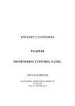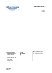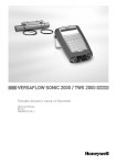
1
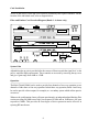
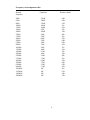
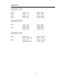
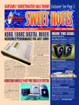
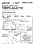
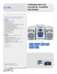
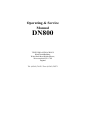
Operating & Service
Manual
DN800
TELEX PRO AUDIO GROUP
Klark Teknik Building,
Walter Nash Road, Kidderminster,
Worcestershire DY11 7HJ
England
Tel: (01562) 741515 Fax: (01562) 745371
DECLARATION OF CONFORMITY
The Directive Covered by this Conformity
89/336/EEC Electromagnetic Compatibility Directive, amended by 92/31/EEC & 93/68/EEC.
73/23/EEC Low Voltage Directive, amended by 93/68/EEC.
The Products Covered by this Declaration
Equipment Type
Graphic Equaliser
Preset Equaliser
Parametric Equaliser
Dynamics Processor
Audio Analyser
Crossover
Delay Line
Programmable Equaliser
Remote Control System
Crossover
Programmable Equaliser
Product Name
DN300
DN320
DN405
DN500
DN6000
DN800
DN7204
DN3600
DN3698
DN8000
DN4000
Variants
DN360, DN301, DN332
DN330
DN410
DN504, DN510, DN514
DN7103
DN3601
DN3603
The Basis on which Conformity is being Declared
The Products named above and hence the Variants thereof listed above comply with the requirements
of the above EU directives by meeting the following standards:
EN 50081-1 (EN55022 class B)
EN 50082-1 (IEC801 Part 2, 4 / ENV 50140 / ENV 50141
EN 60065.
Signed:
Authority:
Date:
...........................
N. G. Tembe
Head of Engineering, EVI Audio (U.K.) Plc
1st January 1997
Attention!
The attention of the specifier, purchaser, installer or user is drawn to the special limitations to use which
must be observed when these products are taken into service to maintain compliance with the above
directives. Details of these special measures and limitations to use are available on request, and are also
contained in product manuals.
CONTENTS
INTRODUCTION
4
USING THE DN800 CONFIGURABLE ACTIVE CROSSOVER
6
FREQUENCY CARD COMPONENT TABLE
9
LIMITER AND PHASE CAPACITOR SELECTION TABLE
10
LIMITER SETUP
11
CONFIGURATIONS
13
SPECIFICATIONS
14
VOLTAGE SELECTION
16
WARRANTY
17
SERVICE REQUEST FORM
18
2-WAY CROSSOVER FILTERBOARD
19
3-WAY CROSSOVER FILTERBOARD
20
4-WAY CROSSOVER FILTERBOARD
21
SCHEMATIC DIAGRAMS
Inputs & Bandpass filters
Band 1-4 Phase & Inserts
Band 1-4 Gain Output & Mute
Power Supply
Band 5-8 Phase & Inserts
Band 5-8 Gain Output & Mute
Signal Present
Filter Board
Limiter A & Power Supply
Limiter B
1
THANK YOU FOR USING THIS KLARK TEKNIK PRODUCT
To obtain maximum performance from this precision electronic product, please study these
instructions carefully. Installation and operating the crossover is not complicated, but the
flexibility provided by its operating features merits familiarisation with its controls and
connections. This unit has been prepared to comply with the power supply requirements that
exist in your location.
Precautions
Before connecting the unit to the mains power, ensure that the operating voltage is correct for
your local supply.
It is important that you observe the following instructions if another voltage setting is required.
Do not install this unit in a location subjected to excessive heat, dust or mechanical vibrations.
Voltage Selection and Power Connection
Connection is made by means of an IEC standard power socket. The rear panel voltage label,
indicates the voltage required for satisfactory operation of the unit.
Before connecting this unit to the mains supply, ensure the fuse fitted is the correct type and
rating is as indicated on the rear panel, adjacent to the fuse holder.
*Mains voltage change should be carried out by a qualified service technician only.
Safety Warning
This unit is fitted with 3-pin power socket: For safety reasons the earth lead should not be
disconnected. Signal 0V is referenced internally to chassis via a resistor capacitor network
which provides earth loop immunity.
To prevent shock or fire hazard, do not expose the unit to rain or moisture. To avoid electrical
shock do not remove covers. Refer servicing to qualified personnel only.
2
After you have unpacked the unit
Save all the packing materials - they will prove valuable should it become necessary to transport or ship this product.
Please inspect this unit carefully for any signs of damage incurred during transportation. It has
undergone stringent quality control inspection and tests prior to packing and left the factory in
perfect condition.
If, however, the unit shows any signs of damage, notify the transportation company without
delay. Only you, the consignee, may institute a claim against the carrier for damage incurred
during transportation.
If necessary, contact your supplier, or as a last resort, your Klark Teknik importing agent,
who will fully co-operate under such circumstances.
3
DN800 Configurable Active Crossover
The Klark Teknik DN800 is a highly specified, active frequency divider designed for use in
sound reinforcement, recording studio and installed sound systems. It may be configured as
a four-input, two-way systems or as a two-input, three or four-way system, the compact, 1U
format making it particularly suitable for use in systems where space is at a premium.
Interchangeable cards are used to set the filter frequency and slope characteristics, while each
band has its own adjustable VCA limiter, the time constants being optimised for the frequency
range covered by that band. The plug-in filter cards offer a choice of 12, 18 or 24 dB/octave
filter slopes with a choice of Linkwitz-Riley, Butterworth or Bessel responses. In many
applications, the Linkwitz-Riley response is the most suitable as it exhibits equal phase shift in
adjacent frequency bands at the filter corner points. Optional equaliser cards may be fitted.
Optional software is available for those users who wish to calculate component values with a
view to populating their own filter boards. This runs on a standard PC computer and
unpopulated filter boards are available.
In two-channel applications, the low bands may be linked to provide a mono feed to sub-bass
or bass systems while in the stereo, three-way mode, the unused fourth band can be used to
provide a direct (un-filtered) feed.
In addition to level and limiter controls, each band is equipped with a phase reverse switch and
a continuously variable phase control (180 degrees maximum) based around an advanced
all-pass filter design. In combination, these controls allow up to 360 degrees phase shift to be
set independently for each band. Full LED status indication is provided for all relevant
parameters in each frequency band.
Provision is made for optional equaliser cards which can provide response ‘tailoring’ for each
crossover band.
Connections
The signal connections are on conventionally wired XLRs (pin 2 hot). As standard, these are
electronically balanced and operate at a nominal +4dBu signal level. Transformer balanced
inputs are available as an option while internal System Gain trims can be used to reset the
output level if required.
4
Installation
Before connecting to the main power supply, ensure that the selector switch adjacent to the
mains inlet socket is set for the correct mains voltage. It is also prudent when first
commissioning the unit to ensure that the correct option boards have been installed.
5
Using the DN800 Configurable Active Crossover
Controls
Before use, the internal links should be set to configure the system for dual, two-band stereo
operation or three or four-band stereo operation. This is achieved by removing the top cover
of the unit and selecting the appropriate link positions.
Note: If the DN800 was ordered to a specific setup requirement, then no internal readjustment
should be required.
Level Control
All eight bands are fitted with Input Gain controls, the 0dB centre position indicating unity
gain. These are located prior to the limiter circuitry in the signal chain and provide +/- 6dB of
control enabling the user to make fine adjustments to the levels in each frequency band to suit
the driver systems being used.
Mute switch
Latching mute switches are provided for each frequency band to assist in setting up and for
checking the correct functioning of individual loudspeaker driver systems. A red status LED
indicates that a band is muted.
Power
Mains power switch. This has no independent status LED as one of the 2-Way, 3-Way or 4Way indicator LEDs will always be on when the unit is powered up.
The remaining controls are located beneath the two security panels and will normally only
require adjustment during the initial setup. The presets require a small screwdriver for
adjustment while the latching switches may be set using a screwdriver, ballpoint pen or similar
tool.
6
Limiter On
Depressing this switch puts the band limiter into circuit.
Limiter Threshold
Controls the limiter threshold over the range -12 to +12dBu. The limiter monitors the signal
after the System Gain preset gain controls and so is not affected by any subsequent
adjustments. The yellow Limit LED illuminates when the output signal reaches the limiter
threshold and the red Over LED comes on when the signal exceeds the limiter threshold by
more than 6dB.
Phase Reverse
Depressing this switch inverts the phase of the signal in the corresponding frequency band (180
degrees shift).
Phase Adjust
This preset provides a continuous adjustment of phase shift from 0 degrees (fully
anticlockwise) to 180 degrees (fully clockwise). This may be used in combination with the
Phase Reverse switch to provide precise phase adjustment up to 360 degrees. Bands 4 & 8
have no variable phase preset as it is normal to set up the lower bands with reference to the
highest.
Mono Bass
Depressing this switch sums the signals in the low frequency bands (Bands 1 & 5) to mono.
This is common practice when feeding bass or sub-bass speaker systems.
Sub Bass
The input stage incorporates a band pass filter operating at 30Hz to 30kHz. The low frequency
response can be extended to 20Hz or 15Hz by replacing 3 filter capacitors on the main board:For input A change capacitors C45, C46, C47
For input C change capacitors C245, C246, C247
For a 30Hz filter (standard value) fit 330nF
For a 20Hz filter fit 470nF
For a 15Hz filter fit 680nF
7
Card Installation
Access to the unit is via the top cover which is retained by four captive fasteners. For the
location of the individual cards, refer to diagram below.
Filter and Limiter Card Location Diagram (Bands 1 - 4 shown only)
System Gain
Adjustable make up gain is provided after the crossover filters to match the signal level to the
power amplifier input requirements. These controls are accessed by removing the top cover
and give a gain range from -6dB to +12dB.
Operation
The Klark Teknik DN800 can be used to provide four channels of two-way operation or two
channels of either three or four-way operation. In dual three-way operation, bands 4 and 8 may
be used to provide a direct output, for example, to a secondary system which utilises passive
crossovers.
Whatever the configuration chosen, all inputs pass through an independent band limiting filter
section providing an 18dB/octave high pass response at 30Hz and an 18dB/octave low pass
response at 30kHz. This provides an extra degree of driver protection and is effective in
rejecting RF interference.
8
Frequency card component table
Desired
frequency
Capacitor
50Hz
63Hz
80Hz
100Hz
125Hz
160Hz
200Hz
250Hz
315Hz
400Hz
500Hz
630Hz
800Hz
1000Hz
1250Hz
1600Hz
2000Hz
2500Hz
3150Hz
4000Hz
5000Hz
6300Hz
8000Hz
10000Hz
12500Hz
16000Hz
20000Hz
330nF
220nF
330nF
100nF
100nF
47nF
100nF
22nF
33nF
68nF
33nF
22nF
33nF
10nF
10nF
4.7nF
10nF
2.2nF
3.3nF
6.8nF
3.3nF
2.2nF
3.3nF
1nF
1nF
1nF
1nF
Resistor (ohm)
6.8k
8.2k
4.3k
11k
9.1k
15k
5.6k
20k
11k
4.3k
6.8k
8.2k
4.3k
11k
9.1k
15k
5.6k
20k
11k
4.3k
6.8k
8.2k
4.3k
11k
9.1k
6.8k
5.6k
9
Limiter and Phase Capacitor Selection Table
Frequency Hz
20
25
31.5
40
50
63
80
100
125
160
200
250
315
400
500
630
800
1k
1k25
1k6
2k
2k5
3k15
4k
5k
6k3
8k
10k
12k5
16k
20k
Limiter Capacitor
20mS
Attack
6.6mS
Attack
2mS
Attack
.66mS
Attack
.2mS
Attack
Phase Capacitor
(Farads)
1uF
1uF
1uF
1uF
1uF
1uF
1uF
1uF
1uF
1uF
1uF
1uF
470nF
470nF
330nF
270nF
220nF
150nF
120nF
100nF
82nF
68nF
47nF
47nF
330nF
330nF
330nF
330nF
330nF
33nF
27nF
22nF
15nF
12nF
100nF
100nF
100nF
100nF
100nF
10nF
8n2F
6n8F
4n7F
4n7F
33nF
33nF
33nF
33nF
33nF
3n3F
2n7F
2n2F
1n5F
1n2F
10nF
10nF
10nF
10nF
1nF
820pF
680pF
470pF
10
Limiter Setup
If the limiters are to be used to eliminate the possibility of power amplifier clipping, they can
be set up by monitoring the clip LEDs on the amplifiers and applying a high level test signal. It
is advisable to run the amplifiers into a dummy load during this operation. The limiter threshold
can then be backed off until the clip LEDs on the amplifier are just extinguished. A more
accurate method is to monitor the amplifier output waveform with an oscilloscope which will
enable the point of clipping to be determined with greater precision. It is recommended that
the limiter be set at least 1dB below the clipping threshold of the power amplifier due to
possible amplifier performance fluctuations during normal use.
If the limiter is required to limit the amplifier power to below its maximum output level, then
the output of the amplifier must be measured at the desired power ceiling and the limiter
threshold set accordingly.
Limiter Time Constants
The Attack and Release Time Constants for the limiters are determined by a capacitor fitted
to the filter card. This is used to “optimise” the limiter protection for the frequency band
selected. When using limiter protection there is always a compromise required between the
degree of protection, the maximum sound pressure level and the amount of distortion when
limiting occurs.
The following table gives some suggested capacitor values to provide reasonably low
distortion while still offering a high degree of protection. The capacitor selection should be
made for the lowest frequency in the crossover filter pass band. For example:
1) A mid frequency driver operating from 500Hz to 2k5Hz should select a limiter capacitor
for 500Hz on the table i.e. 330nF.
2) A low frequency driver should select a limiter capacitor for 30Hz.
11
Phase Adjustment
Because of the mechanical characteristics of loudspeakers and the geometry of their cabinets,
it is generally necessary to adjust the relative phases of the signals feeding drivers in adjacent
bands in order to ensure that the sound from drivers is in phase in the crossover region.
Normally, the highest frequency band is used as a reference and all other bands set in relation
to that. When the phase is optimised, the level of a test frequency equal to the frequency of the
crossover region being optimised will be at a maximum. Hence if, for example, a crossover
point is set to 2.5kHz, a 2.5kHz test signal may be applied and then the phase adjustment
preset of the lower band turned until the signal is at a maximum. If this occurs at one or other
extreme of the preset’s travel, then the Phase Invert button should be operated.
A more reliable method is to adjust the phase preset to give a minimum signal level which will
occur at the point when the signals in the adjacent bands are exactly 180 degrees out of phase.
Once the minimum has been located, the Phase Invert button can be operated to bring the
signals back into phase. Some engineers prefer to make final adjustments while listening to
musical programme material over the system.
The correct sequence when setting up a four-way system is to first adjust the phase of the third
band to align the phase at the crossover point between the third and fourth bands. The process
is then repeated using the appropriate test frequency for the crossover point between the
second and third bands. Finally, the lower crossover point can be optimised using the phase
control preset on the lowest band. If any subsequent adjustment is made to any of the phase
controls, then the bands below it should also be readjusted.
Signal Path
After being de-balanced at the input, the signal is passed through the fixed high and low pass
filters (18dB/octave high pass response at 30Hz and 18dB/octave low pass response at 30kHz)
before being routed to the filter bands via the 2-way or 3/4-way links.
The front panel Gain control is located at the start of the band signal path after which the signal
is passed through the limiter and filter circuitry before encountering the System Gain output
level trim control (internal). There is an additional control input to the limiter taken after the
System Gain control so that any increase in level caused by resetting this control will not cause
the limiting threshold to change. The filtered signal is then balanced and passed to the output
via the muting relay. This relay also mutes the signal during power up to reduce the risk of
loudspeaker damage.
12
Configurations
Four-channel, Two-way
LEDs Indicate: 2 WAY
Input 1
Input 2
Input 3
Input 4
Output 1 Low
Output 3 Low
Output 5 Low
Output 7 Low
Output 2 High.
Output 4 High
Output 6 High.
Output 8 High.
Two-channel, Three-way
LEDs Indicate: 3 WAY
Input 1
Input 2
Output 1 Low
Output 3 High
Output 5 Low
Output 7 High
Output 2 Mid
Output 4 Direct
Output 6 Mid
Output 8 Direct
Two-channel, Four-way
LEDs Indicate: 4 WAY
Input 1
Input 2
Output 1 Low
Output 3 High Mid
Output 5 Low
Output 6 High Mid
Output 2 Low Mid
Output 4 High.
Output 6 Low Mid
Output 8 High
13
Specifications
Inputs
Type
Impedance
Four
Balanced (electronically)
W
Balanced 20k
Unbalanced 10k
Outputs
Type
Min. load impedance
Source impedance
Max. level
Eight
Balanced (electronically)
600W
<60W
>+21dB
Performance
Distortion
Equivalent input noise
Nominal gain
Adjustable gain
Limiter threshold
Phase relationship
Frequency division
filters
<0.01% (20Hz to 20kHz @ 4dB)
<-90dBu (any output)
(20Hz to 20kHz unweighted)
0dB
+ or - 6db on front panel control
additional +12 or -6dB on internal preset
-12dB to +12dB
Continuously adjustable 0 degrees to
180 degrees between bands
Polarity switch provides additional
180 degrees
Butterworth, Bessel or Linkwitz-Riley
12, 18 or 24dB/Oct
Power requirements
Voltage
Consumption
110/120/220/240V 50/60Hz AC
<30 VA
Dimensions
Width
Height
Depth
482mm (19 inches)
44mm (1.75 inches)
285mm (11.2 inches)
Weight
Net
Shipping
3.5kg
6kg
14
Terminations
Inputs
Outputs
Power
3 pin XLR
3 pin XLR
3 pin IEC
Options
Overall security cover
System equalisation
Output balance transformers
15
IMPORTANT WARNING
THIS APPLIANCE MUST BE EARTHED
The wires in the supplied mains lead are coloured in accordance with the following code:
Green and Yellow
Blue
Brown
Earth
Neutral
Live
As the colours of the wires in the mains lead may not be correspond with the coloured markings
identifying the terminals in your plug, proceed as follows:
The wire which is coloured Green and Yellow must be connected to the terminal in the plug that
is marked with the letter E or by the Earth symbol or coloured Green or Green and Yellow.
The wire which is coloured Blue must be connected to the terminal that is marked with the letter
N or coloured Black.
The wire which is coloured Brown must be connected to the terminal which is marked with the
letter L or coloured Red.
Voltage Selection and Power Connection
Connection is made by means of an IEC standard power socket. The rear panel voltage label
indicated the voltage required for satisfactory operation of the unit. Before connecting the unit
to the mains power, ensure that the operating voltage is correct for your local supply. It is
important that you observe the following instructions if another voltage setting is required. The
unit may be set for 240V or 120V operation (50-60Hz) by means of the recessed slide switch
adjacent to the IEC mains inlet socket.
Before connecting this unit to the mains supply, ensure the fuse fitted is the correct type and
rating is as indicated on the rear panel, adjacent to the fuse holder. Should the fuse need
replacing, it should be replaced only with the same type and value of fuse.
Do not install this unit in a location subjected to excessive heat, dust or mechanical vibrations.
16
Warranty
This product is manufactured by Klark Teknik and is warranted to be free from defects in
components and factory workmanship under normal use and service for a period of one year
from the date of purchase.
During the warranty period, Klark Teknik will undertake to repair or at its option, replace this
product at no charge to its owner when failing to perform as specified, provided the unit is
returned shipping prepaid, to the factory or authorised service facility.*
No other warranty is expressed or implied.
This warranty shall not be applicable and be void when this product is subjected to:
a) Repair work or alteration by persons other than those authorised by Klark Teknik in such a
manner as to injure, in the sole judgement of Klark Teknik, the performance, stability, reliability
or safety of this product.
b) Misuse, negligence, accident, act of God, war or civil insurrection.
c) Connection, installation, adjustment or use otherwise than in accordance with the instructions
provided by Klark Teknik.
* See enclosed service request form.
Klark Teknik reserves the right to alter specifications without notice. This warranty does not
affect the statutory rights of the UK customer.
17
COPYMASTER DO NOT REMOVE
NOTE! This sheet is your Copymaster. Please duplicate on photocopier when needed.
Service Request Form
Please complete this form and send it to Klark Teknik before returning the unit. Attach duplicate
to the returned unit.
NAME........................................................TELEPHONE.........................................
ADDRESS..................................................................................................
....................................................................................................................
....................................................................................................................
MODEL No...............................................SERIAL No............................................
PURCHASED FROM............................DATE.........................................................
Please tick appropriate box
REPLACEMENT PACKING REQUIRED
1) Describe symptoms of malfunction.
2) Which channel(s) exhibit(s) the problem?
3) Under what conditions does the problem occur?
a) All the time
b) After a while
c) At high signal levels
d) At high temperatures
e) Other (please explain)
Is the fault:
Permanent
Intermittent
4) What did you do to isolate the problem to this unit?
5) Further comments.
18
YES
NO
2-WAY CROSSOVER FILTERBOARD
30Hz
LF Phase
LF Limit
Not used
HF Limit
Channel 1&2
or 5&6
Lo Pass
Hi Pass
Not used
LF
Hi Pass
HF
Not used
Low pass
Not used
HF Limit
LF Phase
LF Limit
Channel 3&4
or 7&8
30Hz
19
3-WAY CROSSOVER FILTERBOARD
30Hz
LF Phase
LF Limit
M Phase
M Limit
Channel 1&2
or 5&6
Lo Pass
Hi Pass
Lo Pass
LF
M
HF
30Hz
Not used
Hi Pass
Not used
Not used
Full Band
Not used
HF Limit
Channel 3&4
or 7&8
20
4-WAY CROSSOVER FILTERBOARD
30Hz
Lo Pass
Hi Pass
Lo Pass
LF Phase
LF Limit
LM Phase
LM limit
Channel 1&2
5&6
LF
Hi Pass
LM
HM
Hi Pass
HF
Lo Pass
Not used
HF Limit
HM Phase
HM Limit
Channel 3&4
or 7&8
21